- Do-it-yourself grounding schemes for private houses: 380 V and 220 V
- What is a ground loop in a private house: definition and device
- Calculation of grounding for a private house: formulas and examples
- Features of grounding schemes 220 and 380 V
- Circuit design
- Components
- Difference in device location
- Choosing a grounding system for a private house
- Features of the TN-C-S earthing system
- Disadvantage of the TN-C-S system
- Features of the TT earthing system
- TT system installation rules:
- Disadvantages of the TT system:
- How to make a closed-type grounding in a private house without the help of specialists?
- Checking the parameters of the ground loop
- Influence of soil on resistance Rz
- Grounding scheme in a private house
- Connecting a house to a ground loop using the TN-C-S system
- Connecting the house to the ground loop using the TT system
Do-it-yourself grounding schemes for private houses: 380 V and 220 V
When installing ground loops, there is no significant difference between the scheme of a private house for 3 phases (380 volts) and single-phase (220 volts). But in the cabling it is present. Let's figure out what it is.
 Correct entry into the house. This is how it should ideally look.
With a single-phase network, a three-core cable (phase, zero and earth) is used to power electrical appliances. A three-phase network requires a five-wire electrical wire (the same ground and zero, but three phases)
Particular attention should be paid to the disconnection - grounding should not come into contact with zero
Consider the situation. From the substation comes 4 wires (zero and 3 phases), brought into the switchboard. Having arranged the correct grounding on the site, we put it in the shield and “plant” it on a separate bus. Phase and zero cores pass through all automation (RCD), after which they go to electrical appliances. From the ground bus, the core goes directly to sockets and equipment. If the neutral contact is grounded, the residual current devices will work for no reason, and such wiring in the house is completely useless.
Scheme grounding in the country do-it-yourself is simple, but requires a careful and accurate approach when performing. It is easy to perform it for only one boiler or other electrical appliance. Below we will definitely dwell on this.
 The body of the gas boiler, like metal pipes, requires high-quality grounding to avoid sparks
What is a ground loop in a private house: definition and device
A ground loop is a structure of pins and tires located in the ground, providing current removal if necessary. However, not any soil is suitable for a grounding device. Peat, loam or clay soil is considered successful for this, but stone or rock is not suitable.
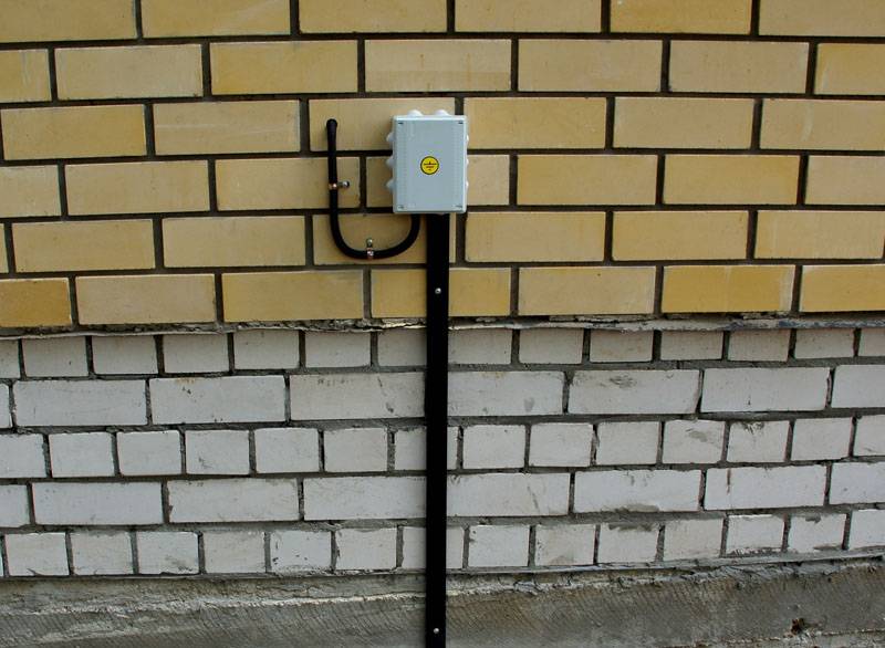
 The contour is ready. It remains to lay the tire to the wall of the house
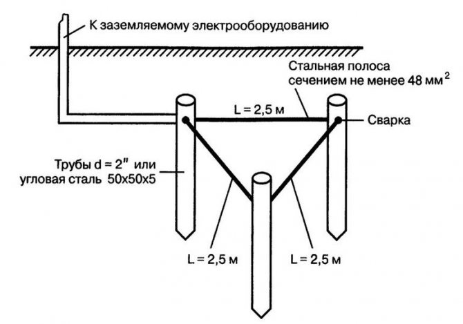
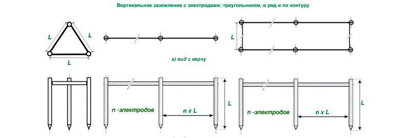
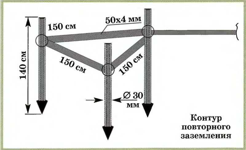
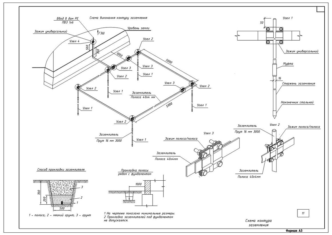
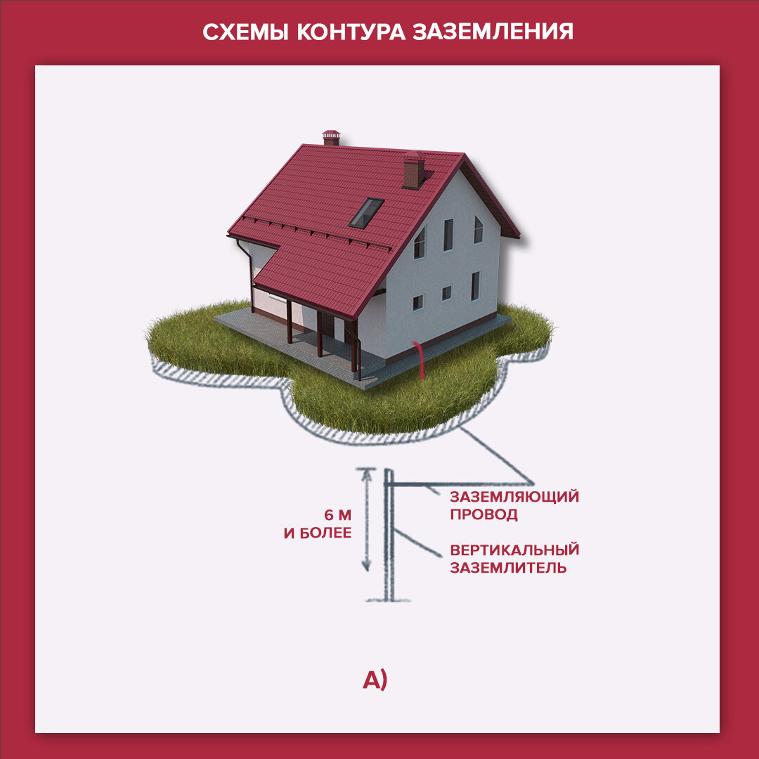
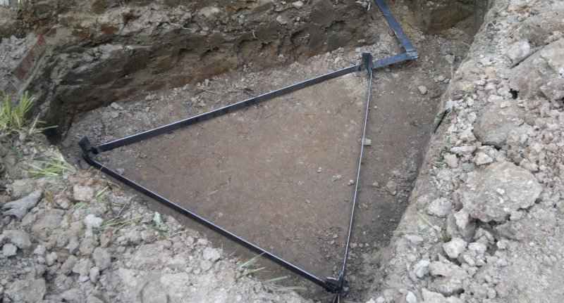
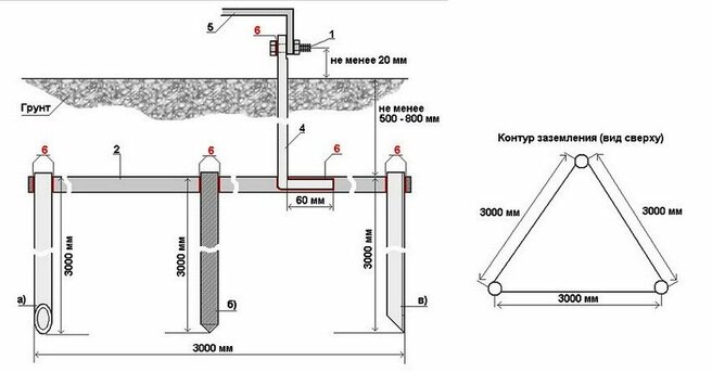
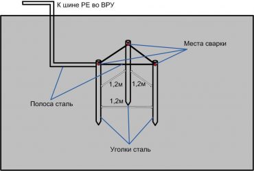
The ground loop is located at a distance of 1 ÷ 10 m from the building. For this, a trench is dug, ending in a triangle. The optimal dimensions are the side lengths of 3 m.At the corners of an equilateral triangle, pin-electrodes are driven in, connected by a steel tire or a corner by welding. From the top of the triangle, the tire goes to the house. We will consider the algorithm of actions in detail in the step-by-step instructions below.
Having figured out what the ground loop is, you can proceed to the calculations of the material and dimensions.
Calculation of grounding for a private house: formulas and examples
The rules for the installation of electrical installations (PUE) and GOST set the exact framework for how many ohms should be grounded. For 220 V - this is 8 ohms, for 380 - 4 ohms. But do not forget that for the overall result, the resistance of the soil in which the ground loop is arranged is also taken into account. This information can be found in the table.
| Soil type | Maximum resistance, Ohm | Minimum resistance, Ohm |
| Alumina | 65 | 55 |
| Humus | 55 | 45 |
| Forest deposits | 25 | 15 |
| Sandstone, groundwater depth deeper than 5 m | 1000 | — |
| Sandstone, ground water not deeper than 5 m | 500 | — |
| Sandy-clay soil | 160 | 140 |
| Loam | 65 | 55 |
| peat bog | 25 | 15 |
| Chernozem | 55 | 45 |
Knowing the data, you can use the formula:
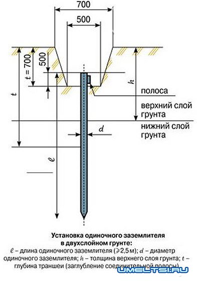
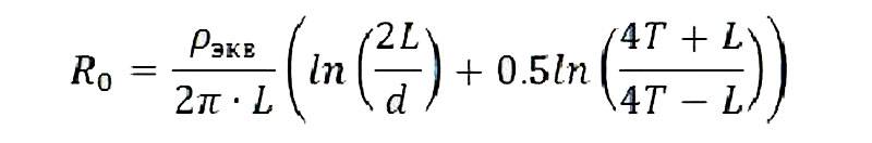 The formula for calculating the resistance of the rod
where:
- Ro – rod resistance, Ohm;
- L is the length of the electrode, m;
- d is the electrode diameter, m;
- T is the distance from the middle of the electrode to the surface, m;
- Req – soil resistance, Ohm;
- T is the distance from the top of the rod to the surface, m;
- ln – distance between pins, m.
But this formula is difficult to use. For simplicity, we suggest using an online calculator, in which you only need to enter data in the appropriate fields and click the calculate button. This will eliminate the possibility of errors in the calculations.


To calculate the number of pins, we use the formula
 Formula for calculating the number of bars in a loop
where Rn is the normalized resistance for the grounding device, and ψ is the climatic coefficient of soil resistance. In Russia, they take 1.7 for it.
Consider an example of grounding for a private house, standing on black soil. If the circuit is made of a steel pipe, 160 cm long and 32 cm in diameter. Substituting the data into the formula, we get no = 25.63 x 1.7/4 = 10.89. Rounding the result up, we get the required number of ground electrodes - 11.
Features of grounding schemes 220 and 380 V
Connection in each case is special. The only thing that remains unchanged is the outer contour. The design can be any (closed, linear). But from the moment you enter the house, you need to take into account some nuances. The same applies to the wiring device. A voltage of 220 volts requires a two-wire line. In this case, one will have to be split into "ground" and "neutral". The other is mounted on insulators.
380 V is an electrical network for which a four-wire system is used. One of the veins is subject to splitting, as in the previous case. The rest are mounted through insulators, without contacting each other. Another feature of this installation method is the need to use additional protective equipment. These are RCDs and differential automata. A "neutral" conductor is brought to them.
Circuit design
Components
Ground loop
The previously mentioned ground resistance (Rz) of the loop is the main parameter controlled at all stages of its operation and determining the effectiveness of its use. This value must be so small as to provide a free path for the emergency current, which tends to drain into the ground.
Note! The most important factor that has a decisive influence on the magnitude of the ground resistance is the quality and condition of the soil at the site of the GD. On this basis, the considered GD or ground loop of the GK (which for our case is the same thing) must have a design that meets the following requirements:
On this basis, the considered GD or ground loop of the GK (which for our case is the same thing) must have a design that meets the following requirements:
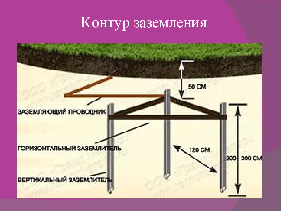
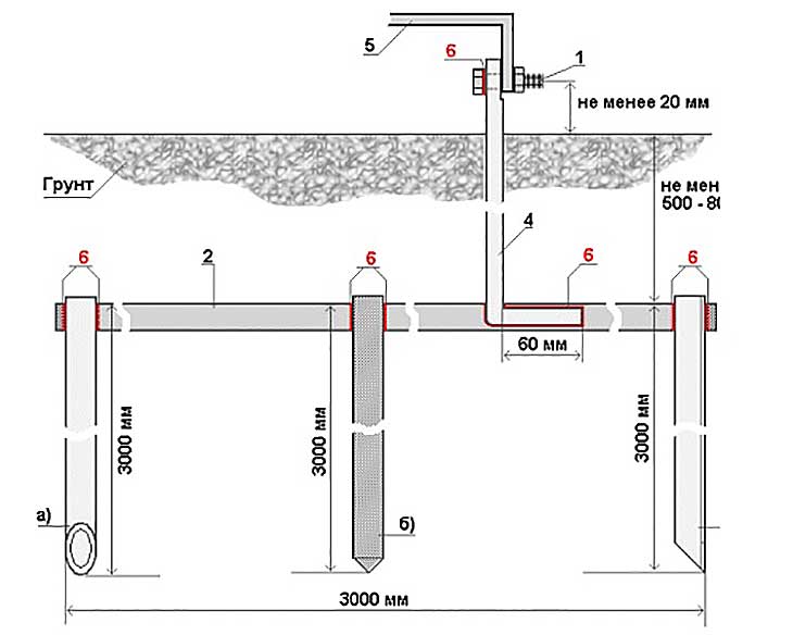
- In its composition, it is necessary to provide a set of metal rods or pins with a length of at least 2 meters and a diameter of 10 to 25 millimeters;
- They are interconnected (mandatory for welding) with plates of the same metal into a structure of a certain shape, forming the so-called "ground electrode";
- In addition, the device kit includes a supply copper bus (it is also called electrical) with a cross section determined by the type of protected equipment and the amount of drain currents (see the table in the figure below).
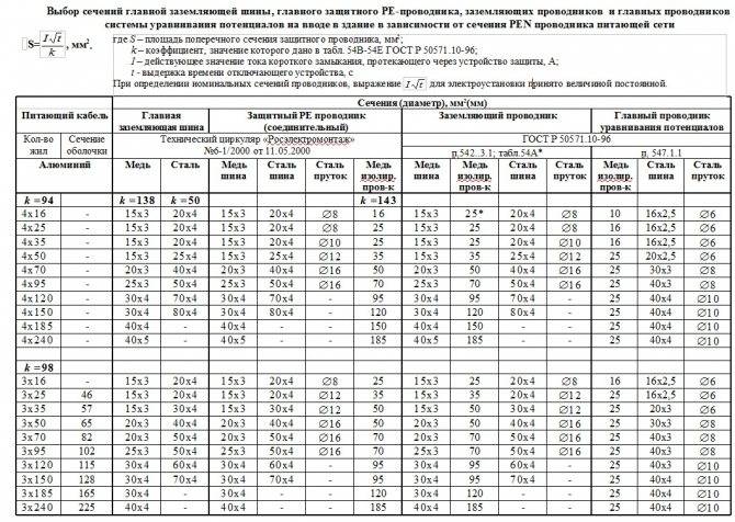
Tire section table
These components of the device are necessary to connect the elements of the protected equipment with a release (copper bus).
Difference in device location
According to the provisions of the PUE, the protective circuit can be both external and internal, and each of them has special requirements. The latter sets not only the permissible resistance of the ground loop, but also specifies the conditions for measuring this parameter in each particular case (outside and inside the object).


When separating grounding systems according to their location, it should be remembered that only for outdoor structures is the correct question of how the resistance of the ground electrode is normalized, since it is usually absent indoors. For internal structures, wiring is typical around the entire perimeter of the premises of electrical buses, to which grounded parts of equipment and devices are connected by means of flexible copper conductors.
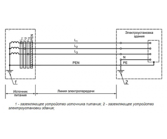
For structural elements grounded outside the object, the concept of re-grounding resistance is introduced, which appeared due to the special organization of protection at the substation. The fact is that when forming a zero protective or working conductor combined with it at the supply station, the neutral point of the equipment (step-down transformer, in particular) is already grounded once.
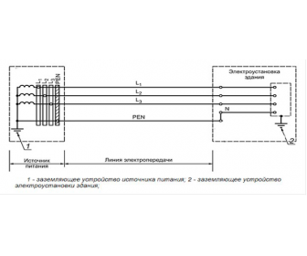
Therefore, when another local ground is made at the opposite end of the same wire (usually a PEN or PE bus, which is output directly to the consumer's shield), it can rightly be called repeated. The organization of this type of protection is shown in the figure below.
Re-grounding
Important! The presence of local or repeated grounding allows you to insure yourself in case of damage to the protective neutral wire PEN (PE - in the TN-C-S power supply system). Such a malfunction in the technical literature is usually found under the name "zero burnout"
Such a malfunction in the technical literature is usually found under the name "zero burnout".
Choosing a grounding system for a private house
You can read the forum, as well as the article ""
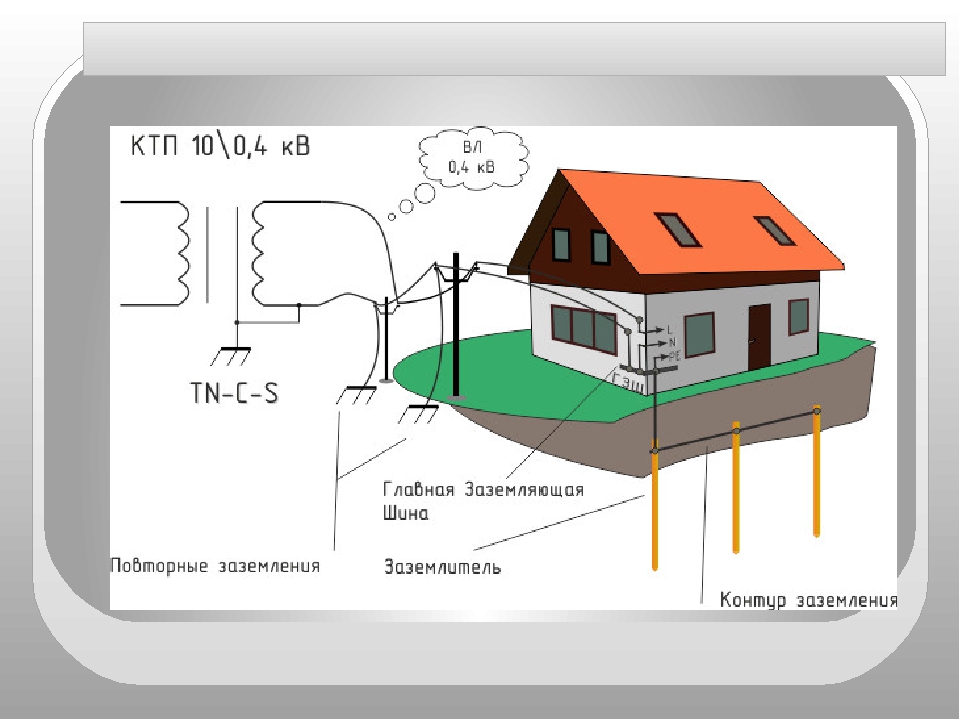
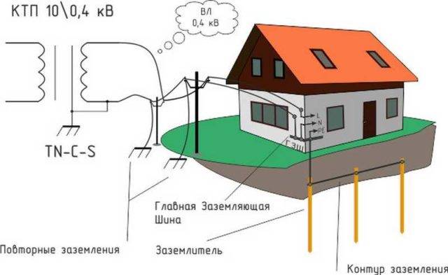
For the modern private sector, only two earthing systems TT and TN-C-S are suitable.Almost the entire private sector is powered by transformer substations with a solidly grounded neutral and a four-wire power transmission line (three phases and PEN, a combined working and protective zero, or, in other words, a combined zero and earth).
Features of the TN-C-S earthing system
According to clause 1.7.61 of the Electrical Installation Code, when using the TN system, it is recommended to re-ground the PE and PEN conductors at the input to the electrical installations of buildings, as well as in other accessible places. Those. the PEN conductor at the entrance to the house is re-grounded and divided into PE and N. After that, 5 or 3 wire wiring is used.
Switching PEN and PE is strictly prohibited (EIC 7.1.21. In all cases, it is forbidden to have switching contact and non-contact elements in the circuits of PE and PEN conductors). The separation point must be upstream of the switching device. It is forbidden to break PE and PEN conductors.
Disadvantage of the TN-C-S system
if the PEN conductor breaks, a dangerous voltage may appear on the cases of grounded electrical appliances.
TN-C-S System Description — TN-C-S System Description
only on modern transmission lines made with SI wire It is recommended to re-ground the PE and PEN conductors at the input to the electrical installations of buildings; re-grounding on power lines must be performed.
According to clause 1.7.135 of the PUE, when the zero working and zero protective conductors are separated starting from any point of the electrical installation, it is not allowed to combine them beyond this point along the course of energy distribution. At the place of division PEN- conductor on the zero protective and zero working conductors, it is necessary to provide separate clamps or busbars for conductors interconnected. PEN- the conductor of the supply line must be connected to the terminal or busbar of the zero protective RE-conductor.


To ensure a high level of safety against electric shock in the TN-C-S system, it is necessary to use residual current devices (RCDs).
Features of the TT earthing system
Description of the TT system - Description of the TT system
the protective conductor PE is grounded independently of the neutral conductor N and any connection between them is prohibited.
The TT system is recommended to be used in case of unsatisfactory condition of the supply overhead power line (VL) (old uninsulated wires of VL, lack of re-grounding on the supports).
Comment
SP 31-106-2002 "DESIGN AND CONSTRUCTION OF ENGINEERING SYSTEMS OF SINGLE APARTMENT BUILDINGS" establishes that the power supply of a residential building must be carried out from 380/220 V networks with a TN-C-S grounding system.
Internal circuits must be made with separate zero protective and zero working (neutral) conductors.
TT system installation rules:
- Installing an RCD at the input with a setting of 100-300 mA (fire RCD).
- Installation of an RCD with a setting of not more than 30 mA (preferably 10 mA - per bathroom) on all group lines (leakage current protection from touching live parts of electrical equipment in case of malfunctions in the house wiring).
- The zero working conductor N must not be connected to the local ground loop and the PE bus.
- To protect electrical appliances from atmospheric surges, it is necessary to install surge arresters (OPN) or surge arresters (OPS or SPD).
- The resistance of the ground loop Rc must satisfy the condition of the PUE (clause 1.7.59):
- with an RCD with a setting of 30 mA, the resistance of the ground loop (ground electrode) is no more than 1666 Ohm;
- with an RCD with a setting of 100 mA, the resistance of the ground loop (ground electrode) is no more than 500 Ohm.
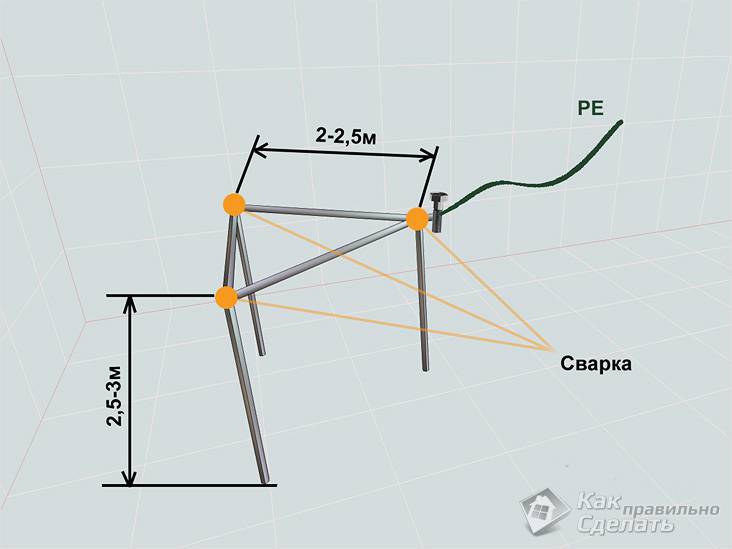
To fulfill the above condition, it will be enough to use one vertical ground electrode in the form of a corner or a rod about 2-2.5 meters long. But I recommend making the circuit more carefully by hammering in several ground electrodes (it won't get worse).
Disadvantages of the TT system:
-
In case of a short circuit of the phase to ground, there will be a dangerous potential on the cases of electrical appliances (the short-circuit current is not enough to trigger the circuit breaker, therefore the installation of an RCD is mandatory - PUE 1.7.59).
This disadvantage of the system can be neutralized by installing a voltage control relay and RCD (2-stage circuit with one "fire" or selective RCD for the whole house and several RCDs on all consumer lines).
I also equipped the indicated 2-stage circuit with one RCD for 100 mA and the 3rd RCD for 30 mA (for each of the phases). This scheme justified itself, turning off the electricity with the help of an RCD, when I hastily put the probes of an incorrectly connected multimeter into the outlet.
How to make a closed-type grounding in a private house without the help of specialists?
After the stage of preparatory work comes the turn of installation. At first glance, the usual task of hammering ground electrodes into the ground can, at least, turn into damaged rolled metal. And all this is due to ignorance of the process technology.
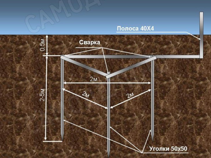
It is important to correctly sharpen the electrodes before driving. Experienced electricians already know how to properly make protective grounding in a private house - they recommend making a point with bevels of 30-35 °
From its edge, you need to retreat 40-45 mm and make a descent of about 45-50 °. A channel, I-beam or Taurus can have several bevels, it is recommended to sharpen the bars by forging. The further process can be seen on the video, it consists in performing the following transitions:


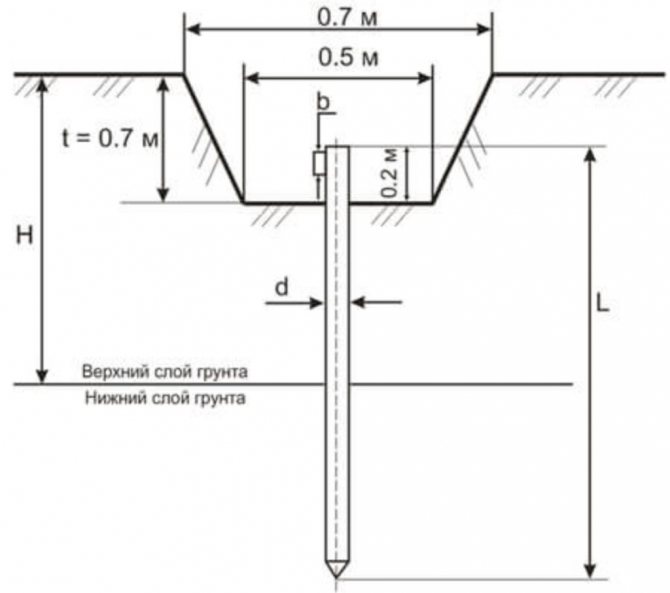
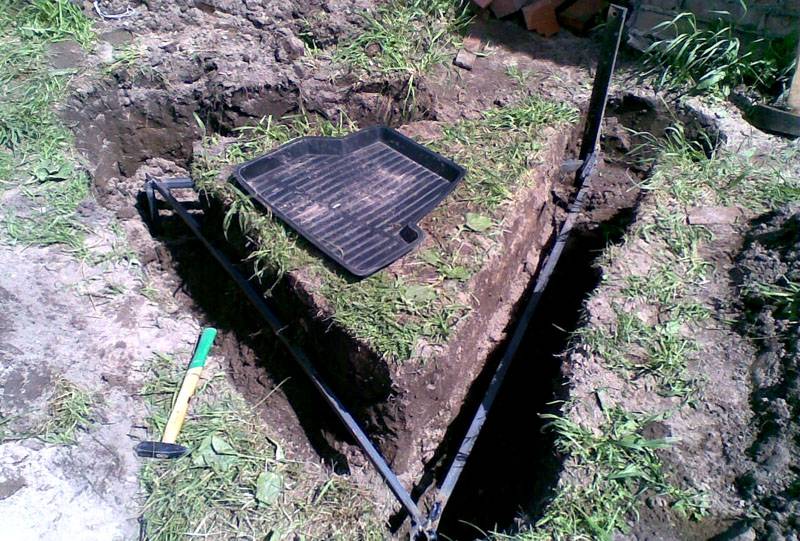
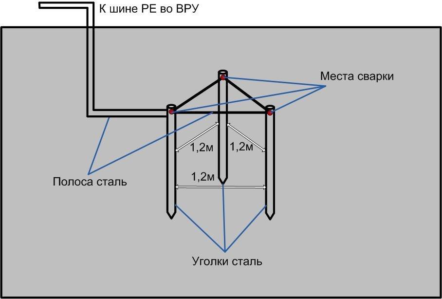
- Using a bayonet shovel, dig an equilateral triangular trench with sides of 1.2 meters, as well as a ditch towards the building for laying a ground bus. Trench depth 50-70 cm.
- For the convenience of driving in the corners of the triangle, holes can be drilled up to a depth of 50 cm.
- Using a sledgehammer or a perforator with a nozzle, hammer in the electrodes, leaving 20-30 cm above the surface of the bottom of the ditch.
- Using electric welding, it is good to weld metal strips to the protruding parts of the ground electrodes.
- Lay a strip connecting the corner of the contour and the foundation of the building, having previously bent it along the profile.
- Weld the ground bar to the corner of the triangle. From the side of the house on the strip, weld a bolt for attaching the copper wire.
- Treat the welding points with anti-corrosion paint or bitumen. Let the paint dry and fill in the ditch.
Checking the parameters of the ground loop
The final stage in the organization of the system is considered to be the measurement of the resistance of the finished circuit, because high-quality protection is needed not only when using a city line, but also when connecting a backup power generator. This stage will indicate how correctly the protective grounding is done in a private house, whether any errors were made during installation. There are several ways to determine resistance:
- Using a 220 volt electric lamp, connecting one contact to the phase and the other to the ground bus.A brightly lit light bulb indicates a well-functioning system, a dimly burning one makes it necessary to check the reliability of the welds.
- Using a ground megaohmmeter, which measures the resistance between the circuit elements and control electrodes driven into the ground to a depth of 15 and 20 meters from ground to a depth of 50 cm.
- With a tester in the state of a voltage meter. The measurement values "phase-zero" and "phase-earth" should not have a significant difference (no more than 10 units).
As such, the protection system does not require maintenance, it is enough to prevent excavation in the area of \u200b\u200bthe contour and moisten the soil in time. The ingress of aggressive substances is also not permissible, since they reduce the life of the structure to 2-3 years.
Influence of soil on resistance Rz
Ground sign
It has been practically proven that the resistance of the grounding device is largely determined by the state of the soil at the location of the ground electrode. In turn, the characteristics of the soil in the area of protection work depend on the following factors:
Soil moisture at the work site;
- The presence of stony components in the soil, in which it is simply impossible to equip grounding (in this case, you have to choose another place);
- The possibility of artificial soil moistening in especially dry summer periods;
- The chemical composition of the soil (the presence of salt components in it).
Depending on the composition of the soil, it can be attributed to one or another type (see photo below).

Different types of soil
Based on the characteristics of the formation of the resistance of the ground electrode, suggesting its decrease with moisture and an increase in salt concentration, in case of emergency, portions of the wet chemical NaCl are artificially introduced into the soil.
Good soils in terms of grounding are loamy soils with a high content of peat components and salts.
Grounding scheme in a private house
As a rule, power supply in private houses is carried out by overhead lines with a TN-C grounding system. In such a system, the neutral of the power supply is grounded, and the phase wire L and the combined zero protective and working wire PEN are suitable for the house.
After the house has installed its own ground loop, it is necessary to connect it to the electrical installations of the house.
- You can do this in two ways:
- convert the TN-C system to the TN-C-S earthing system;
- connect the house to the ground loop using the TT system.
Connecting a house to a ground loop using the TN-C-S system
As you know, the TN-C grounding system does not provide for a separate protective conductor, so in the house we are remaking the TN-C system to TN-C-S. This is done by dividing the combined zero working and protective PEN conductor in the electrical panel into two separate, working N and protective PE.


And so, two supply wires are suitable for your house, phase L and combined PEN. In order to get a three-core electrical wiring in the house with a separate phase, neutral and protective wire, it is necessary to correctly separate the TN-C system into TN-C-S in the introductory electrical panel of the house.
To do this, install a bus in the shield that is metal connected to the shield, this will be the PE ground bus; the PEN conductor will be connected to it from the side of the power source.Further from the PE bus there is a jumper to the bus of the zero working conductor N, the bus of the zero working conductor must be isolated from the shield. Well, you connect the phase wire to a separate bus, which is also isolated from the shield.
After all this, it is necessary to connect the electrical panel to the ground loop of the house. This is done using a stranded copper wire, connect one end of the wire to the electrical panel, and attach the other end to the ground conductor using a bolt at the end, which was specially welded for this purpose.
Connecting the house to the ground loop using the TT system
For such a connection, no separation of the PEN conductor is necessary. Connect the phase wire to a bus isolated from the shield. You connect the combined PEN conductor of the power source to the bus, which is isolated from the shield and further consider PEN as just a neutral wire. Then connect the shield housing to the ground loop of the house.
As can be seen from the diagram, the ground loop of the house has no electrical connection with the PEN conductor. Connecting to ground in this way has several advantages over connecting using the TN-C-S system.
If the PEN conductor on the power supply side burns out, all consumers will be connected to your ground. And this is fraught with many negative consequences. And since your grounding will not have a connection with the PEN conductor, this guarantees zero potential on the body of your electrical appliances.
It often happens that a voltage appears on the neutral conductor due to an uneven load in phases (phase imbalance), which can reach values from 5 to 40 V. And when there is a connection between the network zero and the protective conductor, on the cases of your equipment it can also there is little potential.Of course, if such a situation arises, the RCD should work, but why rely on the RCD. It would be better and more correct not to tempt fate and not lead to such a situation.
From the considered methods of connecting the ground loop at home, we can conclude that the TT system in a private house is safer than the TN-C-S system. The disadvantage of using a TT earthing system is its high cost. That is, when using the TT system, such protective devices as RCDs, voltage relays must be installed.
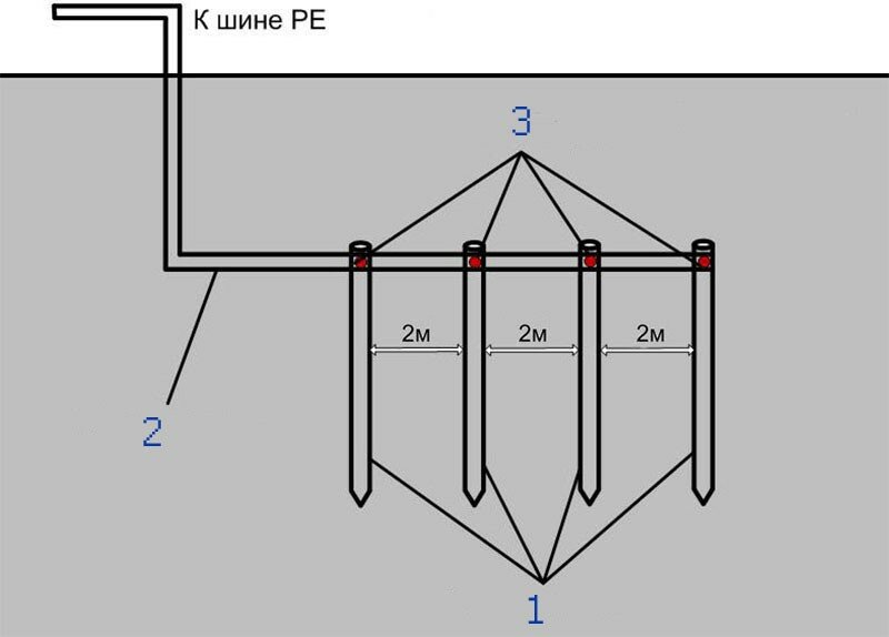
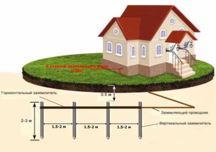
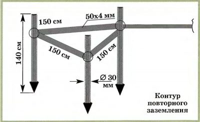
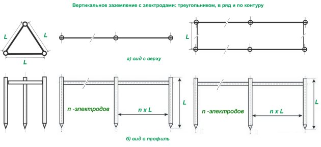
I also wanted to note that it is not necessary to make a contour in the form of a triangle. Everything depends on external conditions. You can arrange horizontal earthing in any order, in a circle or in a single line. The main thing is that their number is sufficient to ensure a minimum ground resistance.


