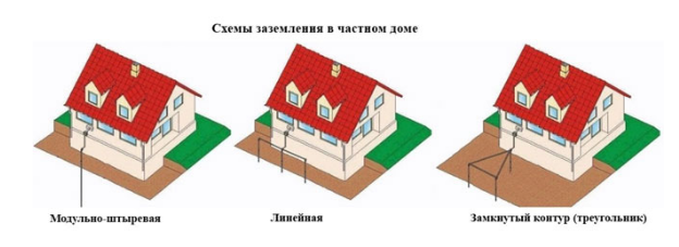
- Types of ground loops
- Triangle - closed loop
- Linear
- Grounding device of a private house
- What to make ground electrodes
- Depth of driving pins
- What Not to Do
- DIY grounding device: step-by-step instructions
- Choosing a place for mounting the ground loop
- Excavation work
- Clogging of ground electrodes
- Welding
- backfilling
- Checking the ground loop
- Features of the installation
- Copper wire
- Pipe racks
- explosive areas
- Internal circuit gasket
- How to connect zero to ground
- What is grounding and why is it needed?
- Why are gas boilers grounded?
- Types of grounding
- Working
- Protective
- Earth resistance
- Types of ground loops
- Triangle - closed loop
- Linear
- DIY grounding device: step-by-step instructions
- Choosing a place for mounting the ground loop
- Excavation work
- Clogging of ground electrodes
- Welding
- backfilling
- Checking the ground loop
Types of ground loops
To quickly "drain" the current into the ground, the external subsystem redistributes it to several electrodes arranged in a certain order to increase the dissipation area. There are 2 main types of connection to the circuit.
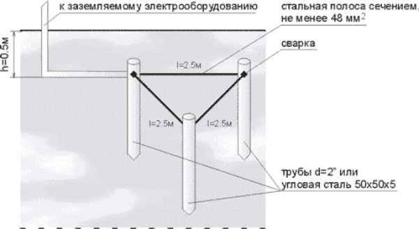
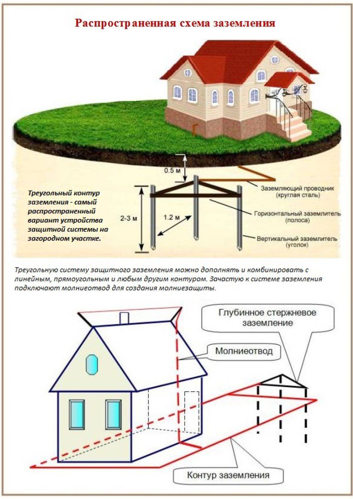
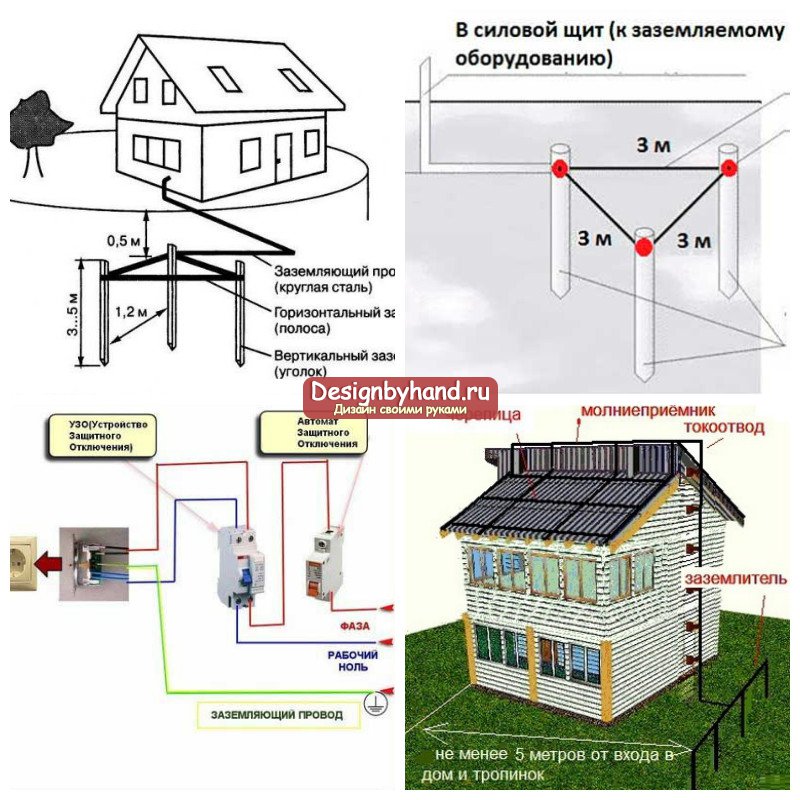
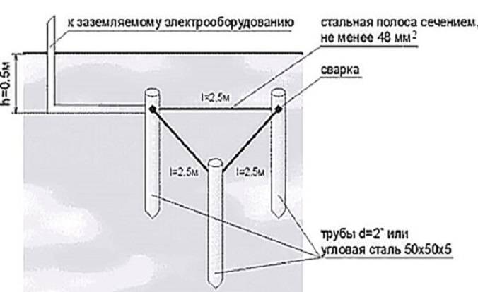
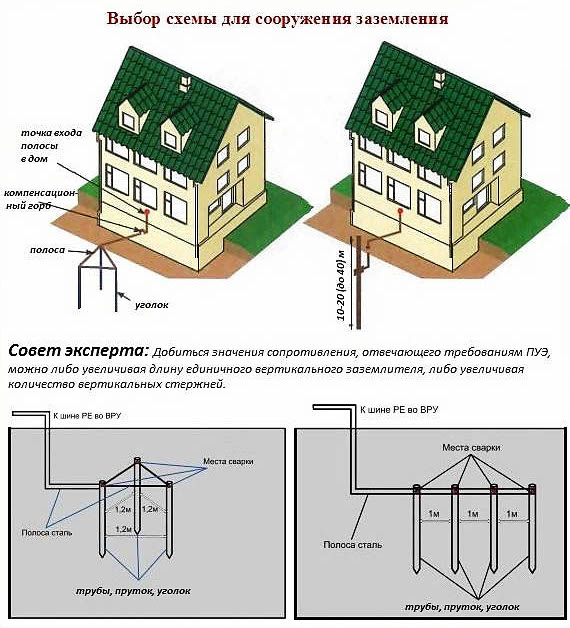
Triangle - closed loop
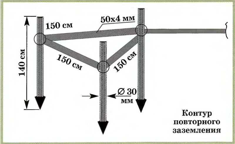
In this case, the current is drained using three pins. They are rigidly connected with iron strips, which become the edges of an isosceles triangle. Before you ground the house in this way, you need to understand the geometric proportions. The following rules apply:
- The number of pins, strips - three.
- The pins are mounted in the corners of the triangle.
- The length of each strip is equal to the length of the rod.
- The minimum depth of the entire structure is about 5 m.
The structure is assembled before the installation of grounding on the surface. The most reliable connection is welded. The tire is made from a strip of sufficient section.
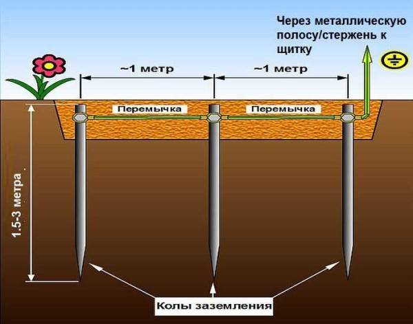
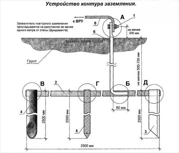
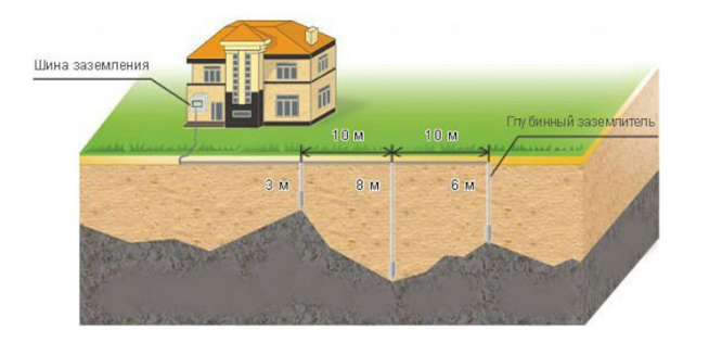
Linear
This option is made up of several electrodes arranged in a line or in a semicircle. An open contour is used in cases where the area of \u200b\u200bthe site does not allow the formation of a closed geometric figure. The distance between the pins is selected within 1-1.5 depth. The disadvantage of this method is an increase in the number of electrodes.
These types are most often used in arranging the grounding of a private house. In principle, a closed loop can be formed in the form of a rectangle, polygon or circle, but more pins will be required. The main advantage of closed systems is the continuation of full operation when the bond between the electrodes is broken.
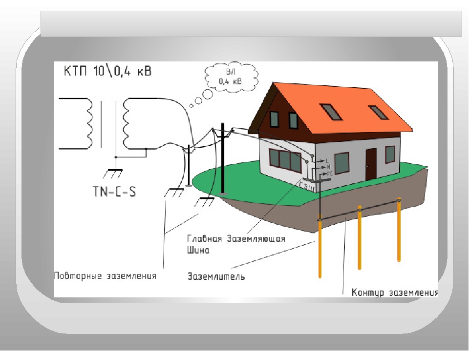
Grounding device of a private house
Some older transmission lines do not have a protective earth at all. All of them should change, but when this will happen is an open question. If you have just such a case, you need to make a separate circuit. There are two options - to make grounding in a private house or in the country on your own, with your own hands, or to entrust the execution of the campaign.Campaign services are expensive, but there is an important plus: if during operation there are problems caused by improper functioning of the grounding system, the company that performed the installation will compensate for the damage (should be written in the contract, read carefully). In the case of self-execution, everything is on you.
Grounding device in a private house
The grounding system of a private house consists of:
- grounding pins,
- metal strips that combine them into one system;
- lines from the ground loop to the electrical panel.
What to make ground electrodes
As pins, you can use a metal rod with a diameter of 16 mm or more. Moreover, it is impossible to take the armature: its surface is hardened, which changes the current distribution. Also, the red-hot layer in the ground is destroyed faster. The second option is a metal corner with 50 mm shelves. These materials are good because they can be hammered into soft ground with a sledgehammer. To make this easier to do, one end is pointed, and a platform is welded to the second, which is easier to hit.
As rods, you can use pipes, angle, metal rod
Sometimes metal pipes are used, one edge of which is flattened (welded) into a cone. Holes are drilled in their lower part (about half a meter from the edge). When the soil dries out, the distribution of the leakage current deteriorates significantly, and such rods can be filled with saline, restoring the operation of the ground. The disadvantage of this method is that you have to dig / drill wells under each rod - it will not work to hammer them with a sledgehammer to the desired depth.
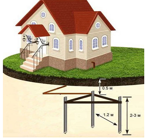
Depth of driving pins
Ground rods should go into the ground below the freezing depth by at least 60-100 cm.In regions with dry summers, it is desirable that the pins be at least partially in moist soil. Therefore, mainly corners or a rod 2-3 m long are used. Such dimensions provide a sufficient area of \u200b\u200bcontact with the ground, which creates normal conditions for dissipating leakage currents.
What Not to Do
The job of a protective earth is to dissipate leakage currents over a large area. This happens due to the tight contact of metal ground electrodes - pins and strips - with the ground. Therefore, grounding elements are never painted. This greatly reduces the conductance between the metal and the ground, the protection becomes ineffective. Corrosion at welding points can be prevented with anti-corrosion compounds, but not with paint.
The second important point: grounding should have low resistance, and good contact is very important for this. It is provided by welding. All joints are welded, and the quality of the seam must be high, without cracks, cavities and other defects
Once again, we draw your attention: grounding in a private house cannot be done on threaded connections. Over time, the metal oxidizes, breaks down, the resistance increases many times, the protection deteriorates or does not work at all
Use only welded joints
It is very unreasonable to use pipelines or other metal structures that are in the ground as a ground electrode. For some time, such grounding in a private house works. But over time, the pipe joints, due to electrochemical corrosion activated by leakage currents, oxidize and collapse, the grounding turns out to be inoperative, as well as the pipeline. Therefore, it is better not to use such types of ground electrodes.
DIY grounding device: step-by-step instructions
If you are wondering: “how to make grounding in the country?”, then the following tool will be required to complete this process:
- welding machine or inverter for welding rolled metal and outputting the circuit to the foundation of the building;
- angle grinder (grinder) for cutting metal into specified pieces;
- nut plugs for bolts with M12 or M14 nuts;
- bayonet and pick-up shovels for digging and digging trenches;
- a sledgehammer for driving electrodes into the ground;
- perforator for breaking stones that can be encountered when digging trenches.
In order to properly and in accordance with regulatory requirements to perform a ground loop in a private house, we need the following materials:
- Corner 50x50x5 - 9 m (3 segments of 3 meters each).
- Steel strip 40x4 (metal thickness 4 mm and product width 40 mm) - 12 m in case of one point of the ground electrode to the building foundation. If you want to make a ground loop throughout the foundation, add the total perimeter of the building to the specified amount and also take a margin for trimming.
- Bolt M12 (M14) with 2 washers and 2 nuts.
- Copper grounding. A grounding conductor of a 3-core cable or a PV-3 wire with a cross section of 6–10 mm² can be used.
After all the necessary materials and tools are available, you can proceed directly to the installation work, which is described in detail in the following chapters.
Choosing a place for mounting the ground loop
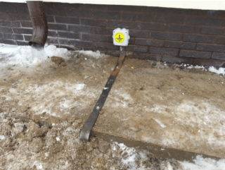
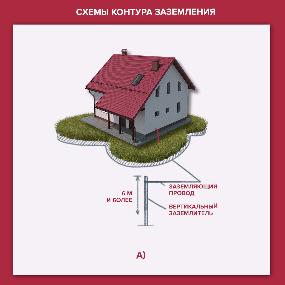
In most cases, it is recommended to mount the ground loop at a distance of 1 m from the foundation of the building in a place where it will be hidden from the human eye and which will be difficult for both people and animals to reach.
Such measures are necessary so that if the insulation in the wiring is damaged, the potential will go to the ground loop and step voltage may occur, which can lead to electrical injury.
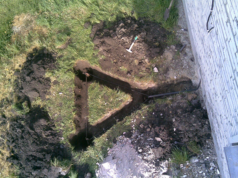
Excavation work
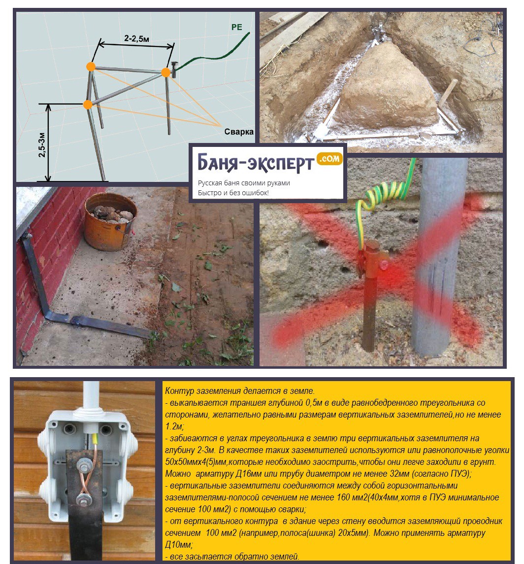
After a place has been chosen, markings have been made (under a triangle with sides of 3 m), the place for the strip with bolts to be placed on the foundation of the building has been determined, earthworks can begin.
To do this, it is necessary to remove a layer of earth of 30–50 cm along the perimeter of the marked triangle with sides of 3 m using a bayonet shovel. This is necessary in order to subsequently weld strip metal to the ground electrodes without any special difficulties.


It is also worth additionally digging a trench of the same depth to bring the strip to the building and bring it to the facade.
Clogging of ground electrodes
After preparing the trench, you can proceed with the installation of the electrodes of the ground loop. To do this, first with the help of a grinder, it is necessary to sharpen the edges of a corner 50x50x5 or round steel with a diameter of 16 (18) mm².
Next, put them at the vertices of the resulting triangle and use a sledgehammer to hammer into the ground to a depth of 3 m
It is also important that the upper parts of the ground electrodes (electrodes) are at the level of the excavated trench so that a strip can be welded to them
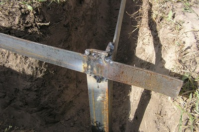
Welding
After the electrodes are hammered to the required depth using a 40x4 mm steel strip, it is necessary to weld the ground electrodes together and bring this strip to the foundation of the building where the ground conductor of the house, cottage or cottage will be connected.
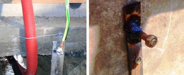
Where the strip will go to the foundation at a height of 0.3–1 mot of the earth, it is necessary to weld the M12 (M14) bolt to which the house grounding will be connected in the future.
backfilling
After all welding work has been completed, the resulting trench can be filled up. However, before that, it is recommended to fill the trench with brine in the proportion of 2-3 packs of salt per bucket of water.
After the resulting soil must be well compacted.
Checking the ground loop
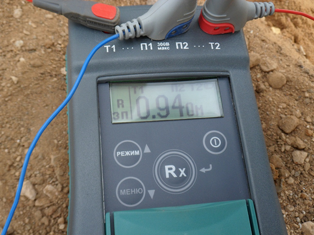
After completing all the installation work, the question arises "how to check the grounding in a private house?". For these purposes, of course, an ordinary multimeter is not suitable, since it has a very large error.
To perform this event, devices F4103-M1, Fluke 1630, 1620 ER pliers and so on are suitable.
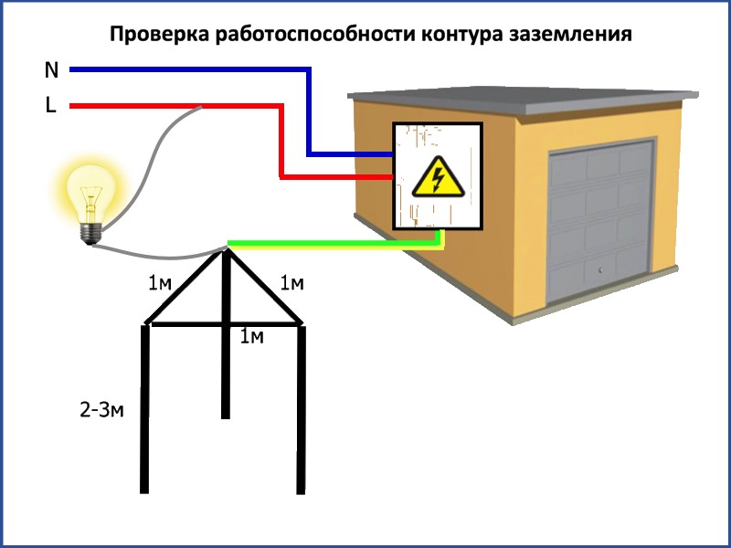
However, these devices are very expensive, and if you do the grounding in the country with your own hands, then an ordinary 150–200 W light bulb will be enough for you to check the circuit. For this test, you need to connect one terminal of the bulb holder to the phase wire (usually brown) and the other to the ground loop.
If the light bulb shines brightly, everything is fine and the ground loop is fully functional, but if the light bulb shines dimly or does not emit a luminous flux at all, then the circuit is mounted incorrectly and you need to either check the welded joints or mount additional electrodes (which happens with low electrical conductivity of the soil).
Features of the installation
Differences in the design of the pipeline grounding system are based on the conditions of their operation.
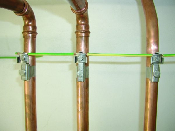
Pipelines laid inside buildings and structures are connected to the natural grounding of buildings and their artificial ground loops.
Other technological equipment is grounded in the same way, including pipe racks, which act as supporting devices in wired communication networks, during the aerial laying of electrical wires and cables.
With the device of additional cathodic protection, which provides anti-corrosion protection of pipelines, the device of the ground loop and the protection itself can be made in one place.

The grounding conductor is fixed to the pipeline by installing a metal clamp equipped with a bolted connection for fastening. The surfaces of the pipeline at the attachment point and the clamp must be cleaned to ensure reliable contact between these elements.
The cross section of the ground conductor, through which the pipeline is connected to the ground electrode, must be:
- for copper conductors without mechanical protection - at least 4 sq. mm;
- for copper conductors with mechanical protection - at least 2.5 sq. mm;
- for aluminum conductors - at least 16 sq. mm.
The spreading resistance of the ground loop, taking into account all repeated groundings, should be no more than:
- for three-phase current networks - 5/10/20 Ohm, at line voltage - 660/380/220 Volts, respectively;
- for single-phase current networks - 5/10/20 Ohm, with a linear voltage of 380/220/127 Volts, respectively.
Copper wire
To ensure the continuity of the metal connection, i.e., the electrical circuit, on pipelines that have flanged or other connections in the design, jumpers are installed with copper wire or other copper conductor.


Copper wire connects pipeline sections connected by using flanges.
For the manufacture of jumpers, as a rule, copper wires of the PuGV or PV3 brands are used; lugs are mounted on their ends by pressing, which are attached to the pipeline by means of a bolted connection.

Pipe racks
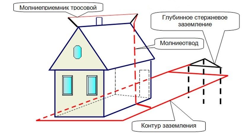
To ensure the safe operation of metal structures installed on the roofs of buildings and other elements of structures, they, including pipe racks, are connected to the building's lightning protection system. Lightning protection is connected to the ground loop.
The connection of the pipe racks with the system is carried out by electric arc welding or by means of a bolted connection.
The requirements for ensuring metal bonding of the structure and the materials used are similar, as in the case of grounding pipelines.
explosive areas
Pipelines come in different designs and for different purposes, which determines the requirements for their operation and protection. These pipelines include:
- gas pipelines and oil pipelines of various pressure;
- transportation systems for alcohol-containing liquids and gases.
If explosive or flammable substances are transported through the pipe system, additional safety requirements are imposed on such pipelines. Device methods in explosive zones are regulated by chapter 7.3 of the PUE.

In explosive premises, the use of natural grounding conductors is allowed only as additional devices, and artificially mounted circuits serve as the main grounding conductor.
Internal circuit gasket
Electrical equipment, which is subject to grounding, is located throughout the area of industrial premises. It is connected to the grounding system by laying busbars inside the building. The installation of grounding conductors is done openly, they should always have free access for control and inspection. The exceptions are metal pipes of hidden electrical wiring and explosive installations, where openings are sealed with easily knocked-out non-combustible materials.
The ground strips of the internal circuit are supposed to be laid horizontally or vertically. Only if the building includes inclined structures is it permitted to run conductors parallel to them. The internal ground loop is mounted using walls and ceilings; if necessary, laying on the floor, the ground strip is laid in the channels. Rectangular conductors are mounted with a wide plane to the wall. The fastening of the strip to brick and concrete surfaces is carried out by driving nails with the help of a construction and assembly gun. Screws are used for fixing on wooden walls.
Grounding conductors are interconnected by welding. With strong heating, the protective zinc coating evaporates, and the steel's resistance to external influences decreases. Therefore, the connection points are treated with zinc spray or enamel. In places where it is provided to measure the resistance of the grounding device, the conductor is bolted. It should be able to detach, but only with a tool. The fixing points of the ground strips should be at a distance of 650 mm to 1000 mm from each other. They are located more often, the larger the cross section of the strip.
The building structure may include expansion joints that protect it from deformation. The ground strip crossing such a seam must have a compensating bend. Through walls and ceilings, the grounding strip is freely passed through openings or enclosed in a steel pipe.
How to connect zero to ground
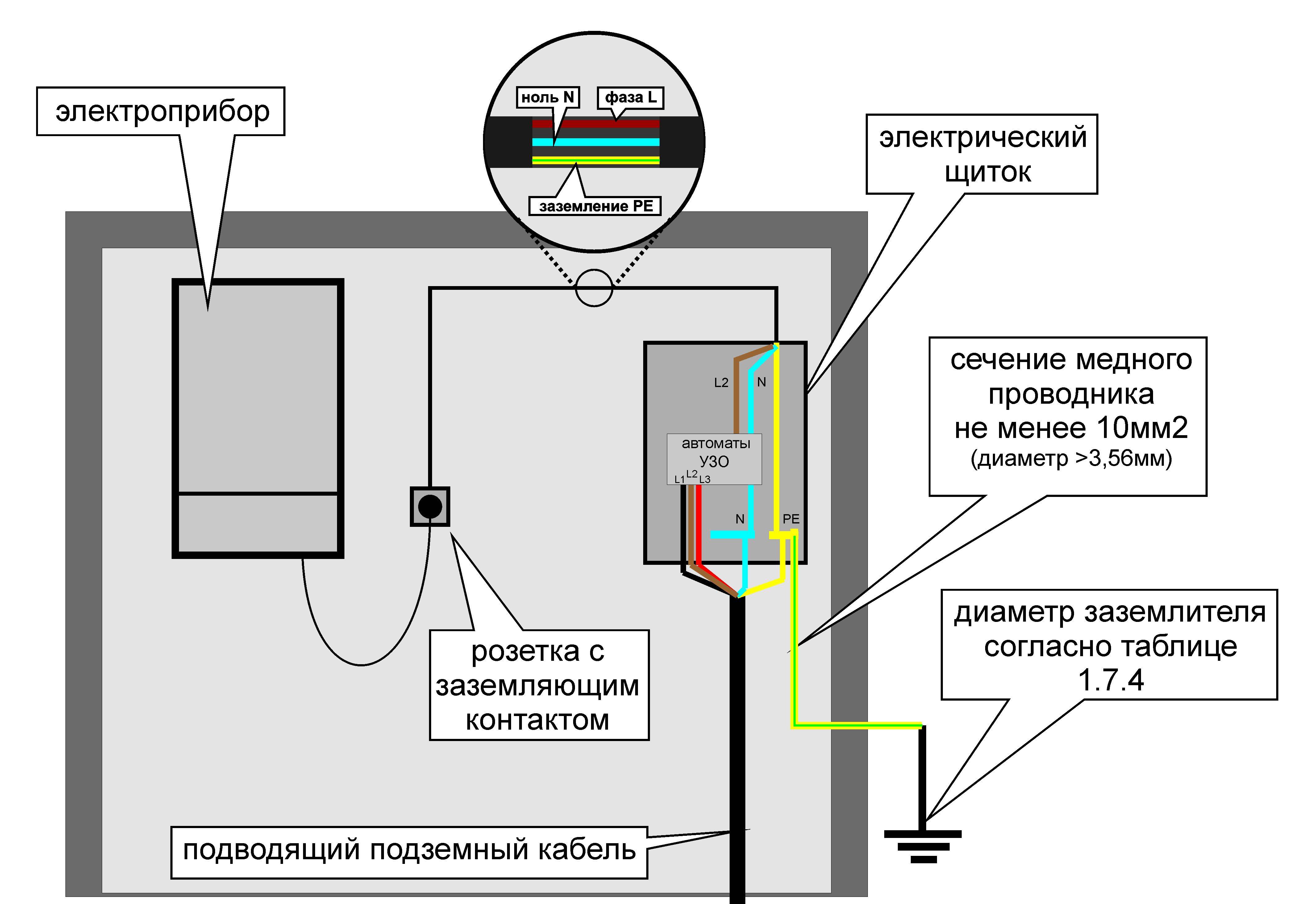
Incorrect connection of zero to earth can cause tragedy instead of protection.In the common house input device (ASU), the combined zero must be separated into working and protective conductors. Then the protective zero should be wired to the shields on the floors, and then to the apartments.
It turns out a five-wire network:
- 3 phase;
- N;
- PE.
PE must be connected to the third contact of the sockets. In old houses there is a four-wire network:
- 3 phase;
- combined zero
If the PE conductor is made in the form of an aluminum bus, then its cross section must be at least 16 mm², if the copper bus (brass) is at least 10 mm2. This rule is valid for the ASU, the rest should be guided by the table below.
22
The protective conductor PE cannot be equipped with circuit breakers, other disconnecting devices, it must be non-switchable. It is necessary to separate the combined zero PEN before the machines and RCDs, after them they should not be connected anywhere!
Forbidden:
- connect the protective and neutral contacts in the socket with a jumper, because. if zero breaks, a dangerous phase voltage will appear on the housings of household appliances;
- connect the neutral and protective conductors with one screw (bolt) on the bus in the shield;
- PE and N must be connected to different busbars, while each wire from each apartment must be screwed with its own screw (bolt). It is necessary to provide for measures against loosening the bolts and protecting them from corrosion and mechanical damage (paragraph 1.7.139 of PUE 7).
Such a connection is used in modern power supply of residential premises or private houses. Which complies with the requirements of PES-7 (clause 7.1.13) for AC and DC networks with a voltage of 220/380 volts. After separation, it is strictly forbidden to combine them.
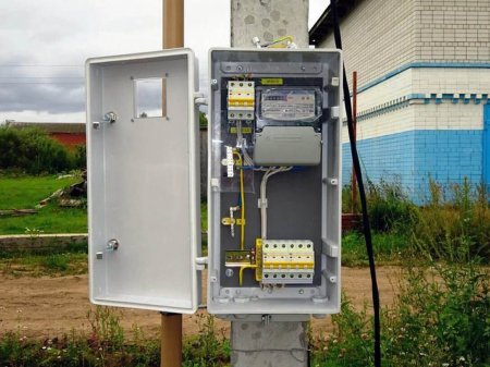
In a private house, we often get two or four wires from high voltage lines.Most often there are 2 situations:
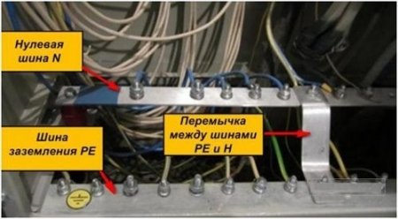
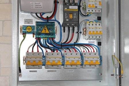
Situation #1 is a good case. Your electrical panel is on a support, a re-grounding is driven in under it. There are two PE and N buses in the electrical panel. Zero from the support and a wire from the ground electrode go to the PE bus. There is a jumper between the PE and N bus, from the N bus there is a working zero to the house, from the PE bus there is a protective zero to the house. PE and N tires can be installed in the house in the switchboard, then zero is connected to the ground on one bus in the metering board as in the photo below.


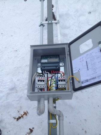
Such shields are now often assembled when connecting new private houses to the power grid. In this case, the introductory machine is installed on the phase, zero from the overhead power line goes directly to the meter, and zero separation (connection to the ground electrode) is made after it. Less often, this is done even before the meter, but often the energy supply is against such a decision. Why? No one knows, they argue with the possibility of theft of electricity (the question is, how?).
If the overhead power line is old, it is not necessary to connect zero and earth (Chapter 1.7. PUE, paragraph 1.7.59). Make a TT system (no PE to N connection). In this case, be sure to use the RCD!
In both situations, each wire on the busbars must be tightened with its own bolt - do not put several PE or N-conductors under one bolt (or screw).
If you live in an apartment, we recommend reading this article.
06.01.2020
What is grounding and why is it needed?
Grounding devices are a deliberate connection of electrical conductors of various points of the electrical network.
The purpose of grounding is to prevent the effects of electric current on a person. Another purpose of protective grounding is to divert voltage from the body of the electrical installation through a grounding device to ground.
The main purpose of grounding is to reduce the potential level between the point that is grounded and the ground. This reduces the current strength to the lowest level and reduces the number of damaging factors in contact with parts of electrical appliances and installations in which a breakdown occurred on the case.
 Watch this video on YouTube
Why are gas boilers grounded?
There are two main reasons why you should pay attention to connecting the heater's steel body to the neutral bus:
- The electronic control systems of the installation are sensitive to various surface currents or statics that accumulate on metal parts during operation. The result of exposure to such undesirable factors may be a malfunction of the processor or its failure.
- With possible gas leaks, the appearance of a spark in most cases leads to an explosion. Grounding neutralizes any potentials or leaks, eliminating the possibility of an accident.
Types of grounding
In the classification of types of grounding, there are two main types of it:
- Working.
- Protective.
There are also several subgroups: radio grounding, measuring, instrumental, control.
Working
There is a certain category of electrical installations that will not work unless they are grounded. That is, the main purpose of the construction of the grounding system is not to ensure the safety of operation, it is to ensure the operation itself. Therefore, in this article we will not be interested in this type.
Protective
But this type is specially arranged in order to ensure the safety of electrical installations. It is divided into three categories depending on the purpose:
- Lightning protection.
- Surge protection (overload of current consumption line or short circuit).
- Protection of the electrical network from electromagnetic interference (most often this type of interference is formed from nearby electrical equipment).
We are interested in the impulse overvoltage. The purpose of this type of grounding is the safety of the operating personnel and the installation itself in the event of an accident or equipment breakdown. Typically, such a breakdown inside an electrical unit is a short circuit of the electrical circuit wire to the device case. The short circuit can occur directly or through any other conductor, for example, through water. A person who touches the body of the installation is exposed to an electric current, because it becomes its conductor to the ground. In fact, he himself becomes part of the ground loop. Grounding scheme in a private house
Expert opinion
Evgeny Popov
Electrician, repairman
That is why, in order to eliminate such situations, the grounding of the case is installed on a circuit located in the ground. At the same time, the operation of the grounding circuit is an impetus for the system of automatic machines, which immediately turn off the power supply to the equipment. All this is located in special power and distribution boards.
Earth resistance
There is such a term as current flow resistance. For ordinary people, it will be easier to perceive it as grounding resistance. The whole point of this term is that the grounding circuit must work correctly with certain parameters. So resistance is the main one.
The optimal value for this value is zero.That is, it is best to use materials for assembling the circuit, which have the highest electrical conductivity. Of course, there is no way to achieve the ideal, so try to choose exactly those with the lowest resistance. All metals are included.
There are special coefficients that are used to determine the resistance index of a ground loop operated in different conditions. For example:
in private housing construction, where networks of 220 and 380 volts (6 and 10 kV) are used, it is necessary to install a circuit with a resistance of 30 ohms.
- the mounted gas pipeline system entering the house must be grounded with a 10 ohm circuit.
- lightning protection should have a resistance of no more than 10 ohms.
- Telecommunications equipment is grounded with a 2 or 4 ohm loop.
- Substations from 10 kV to 110 kV - 0.5 Ohm.
That is, it turns out that the greater the power of the current inside the equipment or devices, the lower the resistance should be.
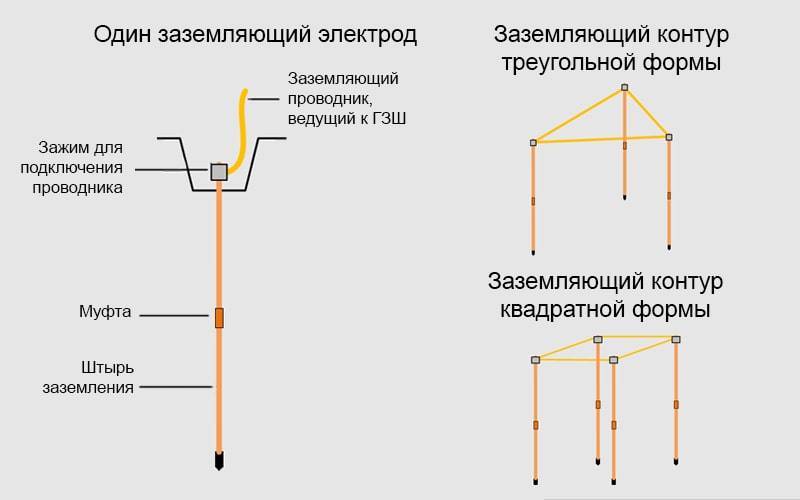
Types of ground loops
The earth is able to "accept" almost any amount of electricity. But for this it is necessary not only to know how to ground, but also to understand the magnitude of the parameters of the system elements. The inner contour of the house takes the load first. Then the current rushes to the electrodes buried in the ground. They, in turn, must be correctly placed and connected. Then the “leaving” of the current will be instantaneous, which means that household appliances will not have time to burn out, and adults, children and pets will not become a victim of electric shock.


Triangle - closed loop
In this case, the current is drained using three pins.They are rigidly connected with iron strips, which become the edges of an isosceles triangle. Before you ground the house in this way, you need to understand the geometric proportions. The following rules apply:
- The number of pins, strips - three.
- The pins are mounted in the corners of the triangle.
- The length of each strip is equal to the length of the rod.
- The minimum depth of the entire structure is about 5 m.
The structure is assembled before the installation of grounding on the surface. The most reliable connection is welded. The tire is made from a strip of sufficient section.
Linear
In this case, three electrodes are also used, which are driven into the ground. Placement points form a straight line or semicircle. The overall dimensions are quite large, and this method is used in areas of sufficient area. The distance between the pins should be equal to the depth or exceed it one and a half times. People often ask how to ground a building if there are several apartments in it? You just need to increase the number of electrodes. The main thing is to keep the distance between them.
You can place them in the form of a triangle, square, rectangle, circle. The main advantage of this type of ground electrode is reliability. All pins are interconnected by a strip. Over time, under the influence of ground and flood waters, the metal can corrode. Over the years, it is possible to break the bonds between the electrodes. But the system will still function as long as the bus remains connected to the structure. However, the disconnected section no longer works, and for repairs it will be necessary to dig out the site and change the elements, eliminate the gap, and connect the connections.
DIY grounding device: step-by-step instructions

If you are wondering: “how to make grounding in the country?”, then the following tool will be required to complete this process:
- welding machine or inverter for welding rolled metal and outputting the circuit to the foundation of the building;
- angle grinder (grinder) for cutting metal into specified pieces;
- nut plugs for bolts with M12 or M14 nuts;
- bayonet and pick-up shovels for digging and digging trenches;
- a sledgehammer for driving electrodes into the ground;
- perforator for breaking stones that can be encountered when digging trenches.
In order to properly and in accordance with regulatory requirements to perform a ground loop in a private house, we need the following materials:
- Corner 50x50x5 - 9 m (3 segments of 3 meters each).
- Steel strip 40x4 (metal thickness 4 mm and product width 40 mm) - 12 m in case of one point of the ground electrode to the building foundation. If you want to make a ground loop throughout the foundation, add the total perimeter of the building to the specified amount and also take a margin for trimming.
- Bolt M12 (M14) with 2 washers and 2 nuts.
- Copper grounding. A grounding conductor of a 3-core cable or a PV-3 wire with a cross section of 6–10 mm² can be used.
After all the necessary materials and tools are available, you can proceed directly to the installation work, which is described in detail in the following chapters.
Choosing a place for mounting the ground loop
In most cases, it is recommended to mount the ground loop at a distance of 1 m from the foundation of the building in a place where it will be hidden from the human eye and which will be difficult for both people and animals to reach.
Such measures are necessary so that if the insulation in the wiring is damaged, the potential will go to the ground loop and step voltage may occur, which can lead to electrical injury.
Excavation work
After a place has been chosen, markings have been made (under a triangle with sides of 3 m), the place for the strip with bolts to be placed on the foundation of the building has been determined, earthworks can begin.
To do this, it is necessary to remove a layer of earth of 30–50 cm along the perimeter of the marked triangle with sides of 3 m using a bayonet shovel. This is necessary in order to subsequently weld strip metal to the ground electrodes without any special difficulties.
It is also worth additionally digging a trench of the same depth to bring the strip to the building and bring it to the facade.
Clogging of ground electrodes
After preparing the trench, you can proceed with the installation of the electrodes of the ground loop. To do this, first with the help of a grinder, it is necessary to sharpen the edges of a corner 50x50x5 or round steel with a diameter of 16 (18) mm².
Next, put them at the vertices of the resulting triangle and use a sledgehammer to hammer into the ground to a depth of 3 m
It is also important that the upper parts of the ground electrodes (electrodes) are at the level of the excavated trench so that a strip can be welded to them
Welding
After the electrodes are hammered to the required depth using a 40x4 mm steel strip, it is necessary to weld the ground electrodes together and bring this strip to the foundation of the building where the ground conductor of the house, cottage or cottage will be connected.
Where the strip will go to the foundation at a height of 0.3–1 mot of the earth, it is necessary to weld the M12 (M14) bolt to which the house grounding will be connected in the future.
backfilling

After all welding work has been completed, the resulting trench can be filled up. However, before that, it is recommended to fill the trench with brine in the proportion of 2-3 packs of salt per bucket of water.


After the resulting soil must be well compacted.
Checking the ground loop
After completing all the installation work, the question arises "how to check the grounding in a private house?". For these purposes, of course, an ordinary multimeter is not suitable, since it has a very large error.
To perform this event, devices F4103-M1, Fluke 1630, 1620 ER pliers and so on are suitable.
However, these devices are very expensive, and if you do the grounding in the country with your own hands, then an ordinary 150–200 W light bulb will be enough for you to check the circuit. For this test, you need to connect one terminal of the bulb holder to the phase wire (usually brown) and the other to the ground loop.
If the light bulb shines brightly, everything is fine and the ground loop fully functional, but if the light bulb shines dimly or does not emit a luminous flux at all, then the circuit is mounted incorrectly and you need to either check the welded joints or mount additional electrodes (which happens with low electrical conductivity of the soil).