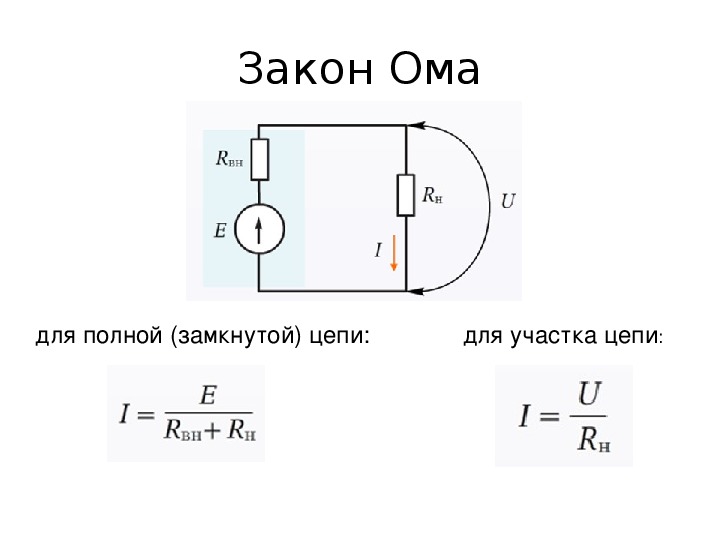
- For closed circuit
- Separate section and complete electrical circuit
- Calculation of the current section of the electrical circuit
- Calculation option for a complete chain
- The effect of the law on a variable
- EMF source in a complete circuit
- R - electrical resistance
- Non-uniform section of the DC circuit
- Serial and parallel connection of elements
- A chain of series-connected resistive elements
- A chain of parallel connected resistive elements
- Integral and differential forms of the law
- Understanding current and resistance
- Ohm's law for alternating current
- When Ohm's law occurs
- Kirchhoff's laws.
- Basic concepts
- Strength and tension
- Conductor resistance
- Ohm's law interpretation
- Parallel and serial connection
- serial connection
- Parallel connection
- What gives us a parallel and serial connection?
- Ideal EMF source
- In differential form
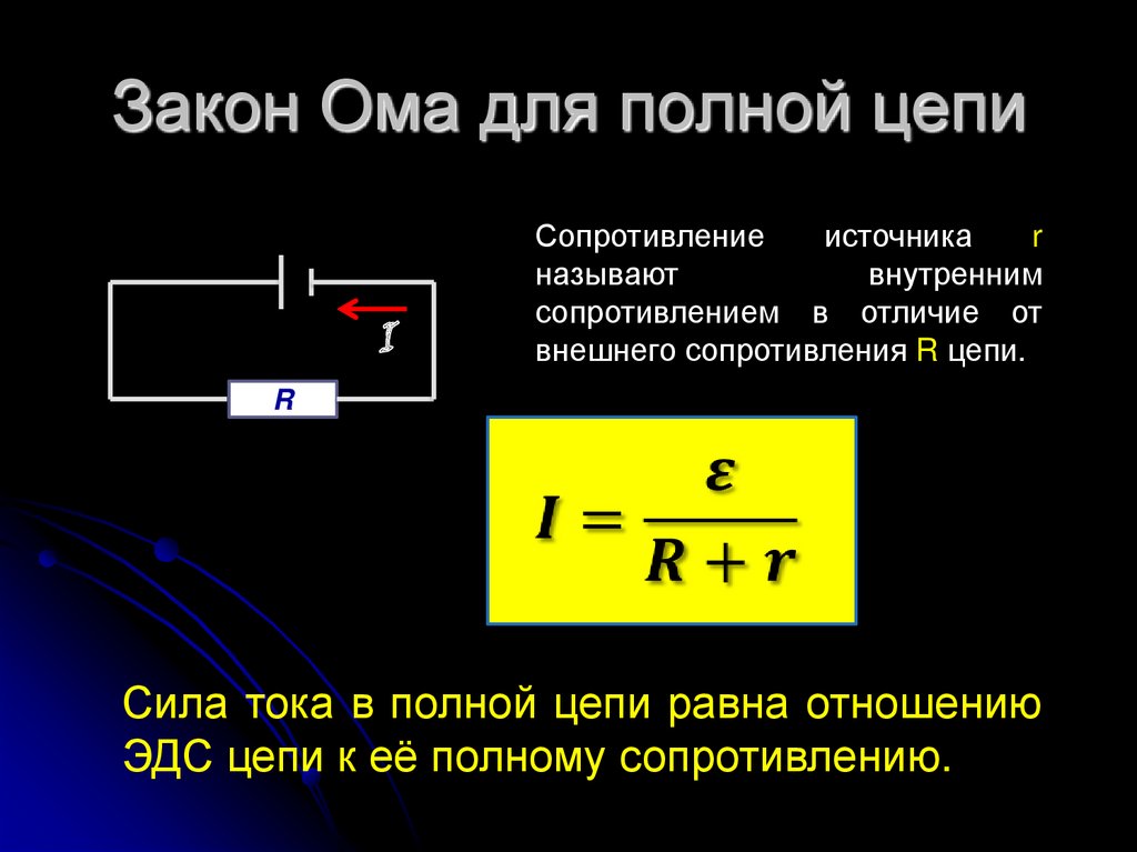
For closed circuit
A closed circuit means a closed electrical connection through which current circulates. When there is a series of wires connecting to each other and completing the circuit so that I runs from one end of the circle to the other, it will be a closed circuit.
EMF (E) - denoted and measured in volts and refers to the voltage generated by a battery or magnetic force according to Faraday's law, which states that a time-varying magnetic field will induce an electric current.
Then: E = IR + Ir
E \u003d I (R + r)
I \u003d E / (R + r)
Where: r is the resistance of the current source.
This expression is known as Ohm's law of closed loop circuits.
Heterogeneous chain
Separate section and complete electrical circuit
Ohm's law, as applied to a section or the entire circuit, can be considered in two calculation options:
- Separate short section. It is part of a circuit without an EMF source.
- A complete chain consisting of one or more sections. This also includes an EMF source with its own internal resistance.
Calculation of the current section of the electrical circuit
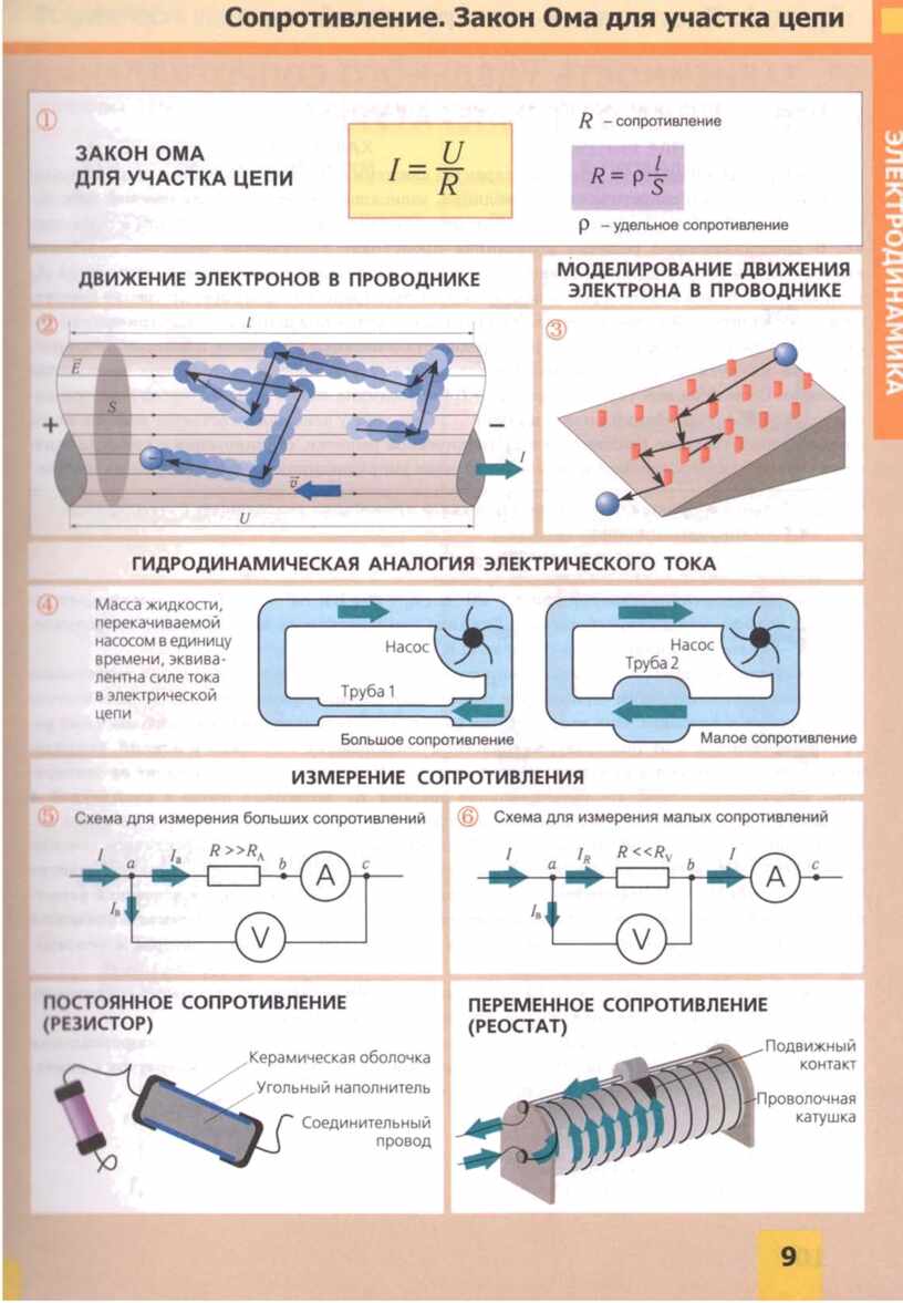
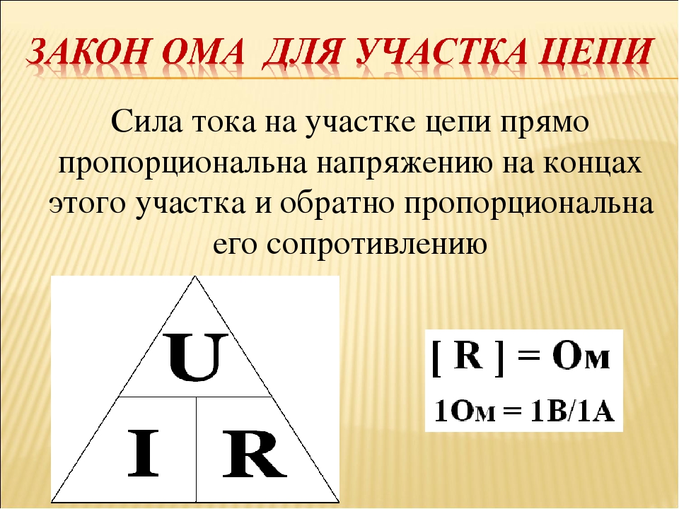
In this case, the basic formula I \u003d U / R is applied, in which I is the current strength, U is the voltage, R is the resistance. According to it, one can formulate the generally accepted interpretation of Ohm's law:
This formulation is the basis for many other formulas presented on the so-called "chamomile" in graphic design. In sector P - power is determined, in sectors I, U and R - actions related to current strength, voltage and resistance are carried out.
Each expression - both basic and additional, allows you to calculate the exact parameters of the elements intended for use in the circuit.
Specialists working with electrical circuits perform a quick determination of any of the parameters using the triangle method shown in the figure.
The calculations should take into account the resistance of the conductors connecting the elements of the section. Since they are made from different materials, this parameter will be different in each case.If it is necessary to form a complete circuit, then the main formula is supplemented with the parameters of a voltage source, for example, a battery.
Calculation option for a complete chain
A complete circuit consists of individual sections, combined into a single whole together with a voltage source (EMF). Thus, the existing resistance of the sections is supplemented by the internal resistance of the connected source. Therefore, the main interpretation discussed earlier will read as follows: I = U / (R + r). Here, the resistive indicator (r) of the EMF source has already been added.
From the point of view of pure physics, this indicator is considered a very small value. However, in practice, when calculating complex circuits and circuits, specialists are forced to take it into account, since additional resistance affects the accuracy of work. In addition, the structure of each source is very heterogeneous, as a result, the resistance in some cases can be expressed by quite high rates.
The above calculations are performed in relation to DC circuits. Actions and calculations with alternating current are made according to a different scheme.
The effect of the law on a variable
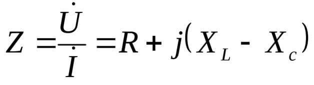
With alternating current, the resistance of the circuit will be the so-called impedance, consisting of active resistance and reactive resistive load. This is due to the presence of elements with inductive properties and a sinusoidal current value. Voltage is also a variable, acting according to its own switching laws.
Therefore, the Ohm's law AC circuit design is calculated taking into account specific effects: leading or lagging the magnitude of the current from the voltage, as well as the presence of active and reactive power.In turn, reactance includes inductive or capacitive components.
All these phenomena will correspond to the formula Z \u003d U / I or Z \u003d R + J * (XL - XC), in which Z is the impedance; R - active load; XL, XC - inductive and capacitive loads; J is the correction factor.
EMF source in a complete circuit
For the occurrence of electric current in a closed circuit, this circuit must contain at least one special element in which the work of transferring charges between its poles will take place. The forces that carry charges inside this element do so against the electric field, which means that their nature must be different from electric. Therefore, such forces are called third-party.
Rice. 1. External forces in physics.
An element of an electrical circuit in which external forces work to transfer charges against the action of an electric field is called a current source. Its main characteristic is the magnitude of external forces. To characterize it, a special measure is introduced - Electromotive Force (EMF), it is denoted by the letter $\mathscr{E}$.
The value of the EMF of the current source is equal to the ratio of external forces for the transfer of charge to the value of this charge:
$$\mathscr{E}={A_{st}\over q}$$
Since the meaning of EMF is very close to the meaning of electrical voltage (recall, voltage is the ratio of the work done by the electric field that carries the charge to the value of this charge), then EMF, like voltage, is measured in Volts:
$$1B={J\overCl}$$
The second most important electrical characteristic of a real current source is its internal resistance.When charges are transferred between the terminals, they interact with the substance of the EMF source, and therefore, the source for electric current also presents some resistance. Internal resistance, like ordinary resistance, is measured in ohms, but is denoted by the small Latin letter $r$.
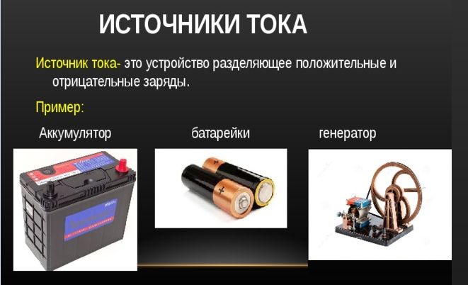
Rice. 2. Examples of current sources.


R - electrical resistance
Resistance is the reciprocal of voltage and can be compared to the effect of moving a body against movement in running water. The unit of R is Om, which is denoted by the capital Greek letter Omega.
The reciprocal of resistance (1/R) is known as conductivity, which measures an object's ability to conduct a charge, expressed in Siemens units.
The geometrically independent quantity used is called resistivity and is usually denoted by the Greek symbol r.
Additional Information. Ohm's law helps to establish three important indicators of the operation of the electrical network, which simplifies the calculation of power. It is not applicable to one-sided networks with elements such as diode, transistor and the like. And also it is not applicable to non-linear elements, of which thyristors are examples, since the resistance value of these elements changes with different given voltage and current.
At higher frequencies, distributed behavior becomes dominant. The same thing happens with very long power lines. Even at a frequency as low as 60 Hz, a very long transmission line, such as 30 km, has a distributed nature. The main reason is that the effective electrical signals propagating in circuits are electromagnetic waves, not volts and amperes, which are infected by an electromagnetic wave.The conductors simply act as guides for the waves. So, for example, a coaxial cable will show Z = 75 ohms, even if its DC resistance is negligible.
Ohm's law is the fundamental law of electrical engineering. It has a large number of practical applications in all electrical circuits and electronic components.
The most common examples of the application of Ohm's law:
- The power supplied to the electric heater. Given the resistance of the heater coil and the applied voltage, the power supplied to that heater can be calculated.
- Choice of fuses. They are protection components that are connected in series with electronic devices. Fuses/CBs are rated in amps. The current fuse rating is calculated using Ohm's law.
- Design of electronic devices. Electronic devices such as laptops and mobile phones require a DC power supply with a specific current rating. Typical mobile phone batteries require 0.7-1A. A resistor is used to control the rate of current flowing through these components. Ohm's law is used to calculate the rated current in a typical circuit.
At one time, Ohm's conclusions became a catalyst for new research in the field of electricity, and today they have not lost their significance, since modern electrical engineering is based on them. In 1841, Om was awarded the Royal Society's highest honor, the Copley Medal, and the term "Om" was recognized as a unit of resistance as early as 1872.
Non-uniform section of the DC circuit
A heterogeneous structure has such a section of the circuit, where, in addition to conductors and elements, there is a current source. Its EMF must be taken into account when calculating the total current strength in this area.
There is a formula that defines the main parameters and processes of a heterogeneous site: q = q0 x n x V. Its indicators are characterized as follows:
- In the process of moving charges (q), they acquire a certain density. Its performance depends on the current strength and the cross-sectional area of \u200b\u200bthe conductor (S).
- Under conditions of a certain concentration (n), it is possible to accurately indicate the number of unit charges (q0) that were moved in a single period of time.
- For calculations, the conductor is conditionally considered a cylindrical section with some volume (V).
When connecting the conductor to the battery, the latter will be discharged after a while. That is, the movement of electrons gradually slows down and, in the end, stops altogether. This is facilitated by the molecular lattice of the conductor, which counteracts the collision of electrons with each other and other factors. To overcome such resistance, certain third-party forces must be additionally applied.
During calculations, these forces are added to the Coulomb ones. In addition, to transfer a unit charge q from the 1st point to the 2nd, it will be necessary to perform the work A1-2 or simply A12. For this purpose, a potential difference (ϕ1 - ϕ2) is created. Under the action of a direct current source, an EMF arises, moving charges along the circuit. The magnitude of the total stress will consist of all the forces noted above.
The polarity of the connection to the DC supply must be taken into account in the calculations. When the terminals are changed, the EMF will also change, accelerating or slowing down the movement of charges.
Serial and parallel connection of elements
For elements of an electrical circuit (section of a circuit), a characteristic moment is a series or parallel connection.
Accordingly, each type of connection is accompanied by a different nature of the current flow and voltage supply. On this account, Ohm's law is also applied in different ways, depending on the option of including elements.
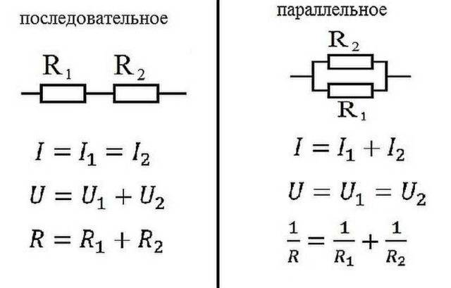
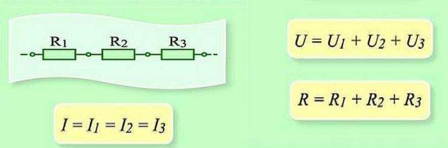
A chain of series-connected resistive elements
With regard to a series connection (section of a circuit with two components), the wording is used:
- I = I1 = I2 ;
- U = U1 + U2 ;
- R=R1 + R2
This formulation clearly demonstrates that, regardless of the number of resistive components connected in series, the current flowing in a section of the circuit does not change value.
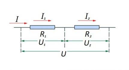 Connecting resistive elements in a circuit section in series with one another. This option has its own calculation law. In the diagram: I, I1, I2 - current flow; R1, R2 - resistive elements; U, U1, U2 - applied voltage
The amount of voltage applied to the active resistive components of the circuit is the sum and adds up to the value of the EMF source.
In this case, the voltage on each individual component is: Ux = I * Rx.
The total resistance should be considered as the sum of the values of all the resistive components of the circuit.
A chain of parallel connected resistive elements
In the case when there is a parallel connection of resistive components, the formulation is considered fair with respect to the law of the German physicist Ohm:
- I = I1 + I2 … ;
- U = U1 = U2 … ;
- 1/R = 1/R1 + 1 / R2 + …
Options for compiling circuit sections of a “mixed” type are not excluded when parallel and serial connections are used.
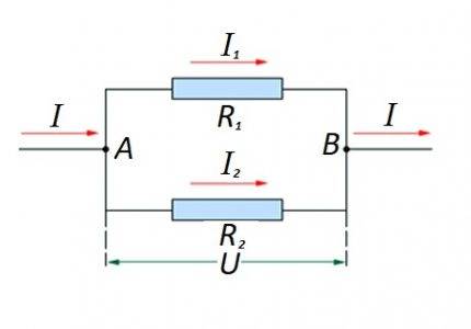 The connection of resistive elements in a circuit section in parallel with one another. For this option, its own calculation law is applied. In the diagram: I, I1, I2 - current flow; R1, R2 - resistive elements; U - applied voltage; A, B - entry / exit points
For such options, the calculation is usually carried out by the initial calculation of the resistive rating of the parallel connection. Then the value of the resistor connected in series is added to the result.
Integral and differential forms of the law
All of the above points with calculations are applicable to conditions when conductors of a “homogeneous” structure, so to speak, are used as part of electrical circuits.
Meanwhile, in practice, one often has to deal with the construction of a schematic, where the structure of the conductors changes in different areas. For example, wires of a larger cross section are used or, on the contrary, smaller ones, made on the basis of different materials.
To take into account such differences, there is a variation of the so-called "differential-integral Ohm's law". For an infinitely small conductor, the current density level is calculated depending on the intensity and the conductivity value.
Under the differential calculation, the formula is taken: J = ό * E
For the integral calculation, respectively, the formulation: I * R = φ1 - φ2 + έ
However, these examples are rather closer to the school of higher mathematics and are not actually used in the real practice of a simple electrician.
Understanding current and resistance
Let's start with the concept of electric current. In short, electric current in relation to metals is the directed movement of electrons - negatively charged particles. They are usually represented as small circles.In a calm state, they move chaotically, constantly changing their direction. Under certain conditions - the appearance of a potential difference - these particles begin a certain movement in some direction. This movement is the electric current.

To make it clearer, we can compare electrons with water spilled on some plane. As long as the plane is stationary, the water does not move. But, as soon as a slope appeared (a potential difference arose), the water began to move. It's the same with electrons.
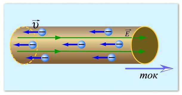
This is how an electric current can be imagined
Now we need to understand what resistance is and why they have feedback with current strength: the higher the resistance, the lower the current. As you know, electrons move through a conductor. Usually these are metal wires, since metals have a good ability to conduct electricity. We know that the metal has a dense crystal lattice: many particles that are close and interconnected. Electrons, making their way between metal atoms, collide with them, which makes it difficult for them to move. This helps to illustrate the resistance that a conductor exerts. Now it becomes clear why the higher the resistance, the lower the current strength - the more particles, the more difficult it is for electrons to overcome the path, they do it more slowly. This seems to have been sorted out.
If you have a desire to test this dependence empirically, find a variable resistor, connect in series a resistor - an ammeter - a current source (battery). It is also desirable to insert a switch into the circuit - an ordinary toggle switch.
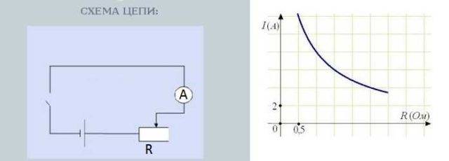
Circuit for testing the dependence of current on resistance
Turning the resistor knob changes the resistance.At the same time, the readings on the ammeter, which measures the current strength, also change. Moreover, the greater the resistance, the less the arrow deviates - the less current. The lower the resistance, the more the arrow deviates - the current is greater.
The dependence of current on resistance is almost linear, that is, it is reflected on the graph as an almost straight line. Why almost - this should be discussed separately, but that's another story.
Ohm's law for alternating current
When calculating AC circuits, instead of the concept of resistance, the concept of "impedance" is introduced. Impedance is denoted by the letter Z, it includes the active resistance of the load Ra and reactance X (or Rr). This is due to the shape of the sinusoidal current (and currents of any other forms) and the parameters of the inductive elements, as well as the switching laws:
- The current in an inductive circuit cannot change instantly.
- The voltage in a circuit with a capacitance cannot change instantly.
Thus, the current begins to lag or lead the voltage, and the apparent power is divided into active and reactive.
U=I/Z
XL and XC are the reactive components of the load.
In this regard, the value cosФ is introduced:
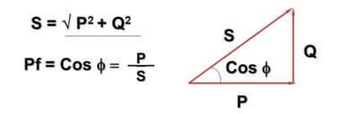
Here - Q - reactive power due to alternating current and inductive-capacitive components, P - active power (dissipated in active components), S - apparent power, cosФ - power factor.
You may have noticed that the formula and its representation intersect with the Pythagorean theorem. This is true and the angle Ф depends on how large the reactive component of the load is - the larger it is, the larger it is. In practice, this leads to the fact that the current actually flowing in the network is greater than that taken into account by a household meter, while enterprises pay for full power.
In this case, the resistance is presented in complex form:
Here j is an imaginary unit, which is typical for the complex form of equations. Less commonly referred to as i, but in electrical engineering, the effective value of the alternating current is also denoted, therefore, in order not to be confused, it is better to use j.
The imaginary unit is √-1. It is logical that there is no such number when squaring, which can result in a negative result of "-1".
When Ohm's law occurs
Creating ideal conditions is not easy. Even in pure conductors, electrical resistance varies with temperature. Its decrease minimizes the activity of the molecules of the crystal lattice, which simplifies the movement of free charges. At a certain level of "freezing" the effect of superconductivity occurs. The opposite effect (deterioration of conductivity) is observed when heated.
At the same time, electrolytes, metals and certain types of ceramics retain electrical resistance regardless of the current density. The stability of the parameters while maintaining a certain temperature regime makes it possible to apply the formulas of Ohm's law without additional corrections.
Semiconductor materials and gases are characterized by varying electrical resistance. This parameter is significantly affected by the current intensity in the control volume. To calculate the performance characteristics, specialized calculation methods must be applied.
If alternating current is considered, the calculation method is corrected. In this case, the presence of reactive components will have to be taken into account. With the resistive nature of the resistance, it is possible to apply the considered calculation technologies based on the formulas of Ohm's law.
Kirchhoff's laws.
Distribution
currents in the branches of the electrical circuit
obeys Kirchhoff's first law,
and the distribution of stresses over sections
chain obeys Kirchhoff's second law.
Kirchhoff's laws
along with Ohm's law are the main
in the theory of electrical circuits.
The first
Kirchhoff's law:
Algebraic
the sum of the currents in the node is zero:
i
= 0 (19)
Where
i
is the number of branches converging at a given node.
That is, summation
extends to the currents in the branches,
which converge in the considered
node.
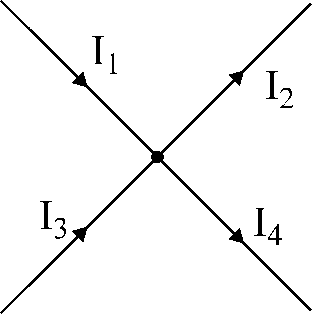
Fig.17. Illustration
to Kirchhoff's first law.


Number
equations compiled according to the first
Kirchhoff's law is determined by the formula:
Nup
= Nu
– 1,
Where
Nu
is the number of nodes in the considered chain.
Signs of currents in
equations are taken taking into account the selected
positive direction. Signs at
currents are the same if the currents are the same
oriented relative to this
node.
For example,
for the node shown in Fig. 17:
we assign signs to the currents flowing to the node
"+", and to the currents flowing from the node - signs
«-».
Then the equation
according to Kirchhoff's first law, it will be written
So:
I1
– I2
+ I3
– I4
= 0.
equations,
compiled according to Kirchhoff's first law,
are called nodes.
This
the law expresses the fact that in the node
electric charge does not accumulate
and is not consumed. The amount of electrical
charges coming to the site is equal to the sum
charges leaving the node in one and the same
same span of time.
Second
Kirchhoff's law:
Algebraic
sum of emf in any closed circuit
chain is equal to the algebraic sum of the falls
voltage on the elements of this circuit:
Ui
=
Ei
IiRi=Ei(20)
Where
i
- element number (resistance or
voltage source) in the considered
contour.
**Number
equations compiled according to the second
Kirchhoff's law is determined by the formula:
Nup
= Nb
- Nu
+ 1 – Ned.s.
Where
Nb
- the number of branches of the electrical circuit;
Nu
— number of nodes;
Ned.s.
is the number of ideal emf sources.
Fig.18. Illustration
to Kirchhoff's second law.
For,
to write the second law correctly
Kirchhoff for a given contour, follows
comply with the following rules:
-
arbitrarily
select the direction of the contour bypass,
for example, clockwise (Fig. 18). -
emf
and voltage drops that match
in the direction with the selected direction
bypass are written in an expression with
sign "+"; if e.f.s. and voltage drop
do not match direction
contour, then they are preceded by a sign
«-».
For example,
for the contour of Fig. 18, Kirchhoff's second law
will be written as follows:
U1
– U2
+ U3
=E1
–E3
–E4
(21)
Equation (20) can be
rewrite as:
(Ui
– Ei)
= 0 (22)
Where
(U
– E)
- tension on the branch.
Consequently,
Kirchhoff's second law can be formulated
in the following way:
Algebraic
the sum of the voltages on the branches in any
closed loop is zero.
Potential
the diagram discussed earlier serves
graphical interpretation of the second
Kirchhoff's law.
Task number 1.
AT
the circuit in Fig. 1 is given currents I1
and I3,
resistance and emf Determine currents
I4,
I5,
I6
; voltage between points a
and b
if I1
= 10mA,
I3
= -20 mA,
R4
= 5kOhm,
E5
= 20B,
R5
= 3kOhm,
E6
= 40B,
R6
= 2kOhm.
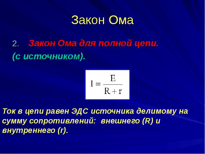


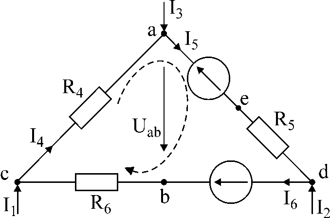
Fig.1
Solution:
-
For a given
contour, we compose two equations according to
Kirchhoff's first law and one - according to
second. Contour direction
indicated by an arrow.

AT
as a result of the solution we get: I6
= 0; I4
= 10mA;
I5
= -10mA
-
ask
voltage direction between points
a
and b
from point "a"
to point "b"
— Uab.
This voltage can be found from the equation
Kirchhoff's second law:
I4R4
+ Uab
+ I6R6
= 0
Uab
= - 50V.
Task number 2.
For
diagrams in Fig. 2 draw up equations according to
Kirchhoff's laws and determine the unknowns
points.
Given:
I1
= 20mA;
I2
= 10mA
R1
= 5kOhm,
R3
= 4kOhm,
R4
= 6kOhm,
R5
= 2kOhm,
R6
= 4kΩ.
Fig.2
Solution:
Number of nodes
equations - 3, the number of contour equations
– 1.
Remember!
When compiling the equation according to the second
Kirchhoff's law, we choose the contour, in
which does not include current sources.
The direction of the contour is indicated in the figure.
AT
of this circuit, the currents of the branches I1
and I2.
Unknown
currents
I3,
I4,
I5,
I6.

Deciding
system, we get: I3
= 13.75 mA;
I4
= -3.75mA;
I5
= 6.25mA;
I6
= 16.25mA.
Basic concepts
Electric current flows when a closed circuit allows electrons to move from a high potential to a lower one in the circuit. In other words, the current requires a source of electrons that has the energy to set them in motion, as well as a point of their return of negative charges, which is characterized by their deficiency. As a physical phenomenon, the current in a circuit is characterized by three fundamental quantities:
- voltage;
- current strength;
- the resistance of a conductor through which electrons move.
Strength and tension
The current strength (I, measured in Amperes) is the volume of electrons (charge) moving through a place in the circuit per unit of time. In other words, measurement I is the determination of the number of electrons in motion
It is important to understand that the term refers only to movement: static charges, for example, on the terminals of an unconnected battery, do not have a measurable value of I. Current that flows in one direction is called direct (DC), and periodically changing direction is called alternating (AC). Voltage can be illustrated by such a phenomenon as pressure, or as the difference in the potential energy of objects under the influence of gravity
In order to create this imbalance, you must first expend energy, which will be realized in motion under appropriate circumstances. For example, in the fall of a load from a height, work is carried out to lift it, in galvanic batteries, the potential difference at the terminals is formed due to the conversion of chemical energy, in generators - as a result of exposure to an electromagnetic field
Stress can be illustrated by such a phenomenon as pressure, or as the difference in the potential energy of objects under the influence of gravity. In order to create this imbalance, you must first expend energy, which will be realized in motion under appropriate circumstances. For example, in the fall of a load from a height, the work of lifting it is realized, in galvanic batteries the potential difference at the terminals is formed due to the conversion of chemical energy, in generators - as a result of exposure to an electromagnetic field.
Conductor resistance
No matter how good an ordinary conductor is, it will never allow electrons to pass through without some resistance to their movement. It is possible to consider resistance as an analog of mechanical friction, although this comparison will not be perfect.When current flows through a conductor, some potential difference is converted into heat, so there will always be a voltage drop across the resistor. Electric heaters, hair dryers and other similar devices are designed solely to dissipate electrical energy in the form of heat.
Simplified resistance (denoted as R) is a measure of how much the flow of electrons is retarded in a circuit. It is measured in ohms. The conductivity of a resistor or other element is determined by two properties:
- geometry;
- material.
Shape is of the utmost importance, as is evident from the hydraulic analogy: pushing water through a long and narrow pipe is much harder than pushing water through a short and wide one. Materials play a decisive role. For example, electrons can move freely in a copper wire, but cannot flow at all through insulators such as rubber, regardless of their shape. In addition to geometry and material, there are other factors that affect conductivity.
Ohm's law interpretation
To ensure the movement of charges, you need to close the circuit. In the absence of additional power, the current cannot exist for a long time. Potentials will quickly become equal. To maintain the operating mode of the circuit, an additional source (generator, battery) is needed.
The complete circuit will contain the total electrical resistance of all components. For accurate calculations, losses in conductors, resistive elements, and a power source are taken into account.
How much voltage needs to be applied for a certain current strength is calculated by the formula:
U=I*R.
Similarly, with the help of the considered relations, other parameters of the circuit are determined.
Parallel and serial connection
In electrics, elements are connected either in series - one after the other, or in parallel - this is when several inputs are connected to one point, and outputs from the same elements are connected to another.
Ohm's law for parallel and series connection
serial connection
How does Ohm's law work for these cases? When connected in series, the current flowing through the chain of elements will be the same. The voltage of a section of a circuit with elements connected in series is calculated as the sum of the voltages in each section. How can this be explained? The flow of current through an element is the transfer of part of the charge from one part of it to another. I mean, it's some work. The magnitude of this work is tension. This is the physical meaning of stress. If this is clear, we move on.
Serial connection and parameters of this section of the circuit
When connected in series, it is necessary to transfer the charge in turn through each element. And on each element, this is a certain “volume” of work. And to find the amount of work on the entire section of the chain, you need to add the work on each element. So it turns out that the total voltage is the sum of the voltages on each of the elements.
In the same way - with the help of addition - the total resistance of the circuit section is also found. How can you imagine it? The current flowing through the chain of elements sequentially overcomes all resistances. One by one. That is, to find the resistance that he overcame, it is necessary to add up the resistances. More or less like this. The mathematical derivation is more complicated, and it is easier to understand the mechanism of this law.
Parallel connection
A parallel connection is when the beginnings of the conductors / elements converge at one point, and at another their ends are connected. We will try to explain the laws that are valid for compounds of this type. Let's start with current. A current of some magnitude is supplied to the connection point of the elements. It separates, flowing through all the conductors. From this we conclude that the total current in the section is equal to the sum of the current in each of the elements: I = I1 + I2 + I3.
Now for the voltage. If voltage is work to move a charge, then the work that is needed to move one charge will be the same on any element. That is, the voltage on each parallel connected element will be the same. U=U1=U2=U3. Not as fun and visual as in the case of the explanation of Ohm's law for a chain section, but you can understand.
Laws for Parallel Connection
For resistance, things are a bit more complicated. Let's introduce the concept of conductivity. This is a characteristic that indicates how easy or difficult it is for a charge to pass through this conductor. It is clear that the lower the resistance, the easier it will be for the current to pass. Therefore, conductivity - G - is calculated as the reciprocal of resistance. In the formula, it looks like this: G = 1/R.
Why are we talking about conductivity? Because the total conductivity of a section with a parallel connection of elements is equal to the sum of the conductivity for each of the sections. G = G1 + G2 + G3 - easy to understand. How easily the current will overcome this node of parallel elements depends on the conductivity of each of the elements. So it turns out that they need to be folded.
Now we can move on to resistance. Since conductivity is the reciprocal of resistance, we can get the following formula: 1/R = 1/R1 + 1/R2 + 1/R3.
What gives us a parallel and serial connection?
Theoretical knowledge is good, but how to apply it in practice? Elements of any type can be connected in parallel and in series. But we considered only the simplest formulas describing linear elements. Linear elements are resistances, which are also called "resistors". So here's how you can use what you've learned:
If there is no large-value resistor available, but there are several smaller ones, the desired resistance can be obtained by connecting several resistors in series. As you can see, this is a useful trick.
To extend the life of the batteries, they can be connected in parallel. In this case, the voltage, according to Ohm's law, will remain the same (you can make sure by measuring the voltage with a multimeter). And the “lifetime” of a dual battery will be much longer than that of two elements that will replace each other
Just note: only power supplies with the same potential can be connected in parallel. That is, a dead and a new battery cannot be connected.
If you still connect, the battery that has a larger charge will tend to charge a less charged one. As a result, their total charge will drop to a low value.
In general, these are the most common uses for these compounds.
Ideal EMF source
The electromotive force (E) is a physical quantity that determines the degree of influence of external forces on the movement in a closed circuit of charge carriers. In other words, how strongly the current tends to flow through the conductor will depend on the EMF.
When explaining such incomprehensible phenomena, domestic school teachers like to turn to the method of hydraulic analogies.If a conductor is a pipe, and electric current is the amount of water flowing through it, then EMF is the pressure that a pump develops to pump fluid.
The term electromotive force is related to such a concept as voltage. She, EMF, is also measured in volts (unit - "V"). Every power source, be it a battery, a generator or a solar panel, has its own electromotive force. Often this EMF is close to the output voltage (U), but always slightly less than it. This is caused by the internal resistance of the source, on which part of the voltage inevitably drops.
For this reason, the ideal source of EMF is rather an abstract concept or a physical model that has no place in the real world, because the internal resistance of the battery Rin, although very low, is still different from absolute zero.
Ideal and real source of emf
In differential form
The formula is very often presented in a differential form, since the conductor is usually inhomogeneous and it will be necessary to break it into the smallest possible sections. The current passing through it is associated with magnitude and direction, so it is considered a scalar quantity. Whenever the resultant current through a wire is to be found, the algebraic sum of all the individual currents is taken. Since this rule only applies to scalar quantities, the current is also taken as a scalar quantity. It is known that the current dI = jdS passes through the section. The voltage on it is equal to Edl, then for a wire with a constant cross section and equal length, the ratio will be true:
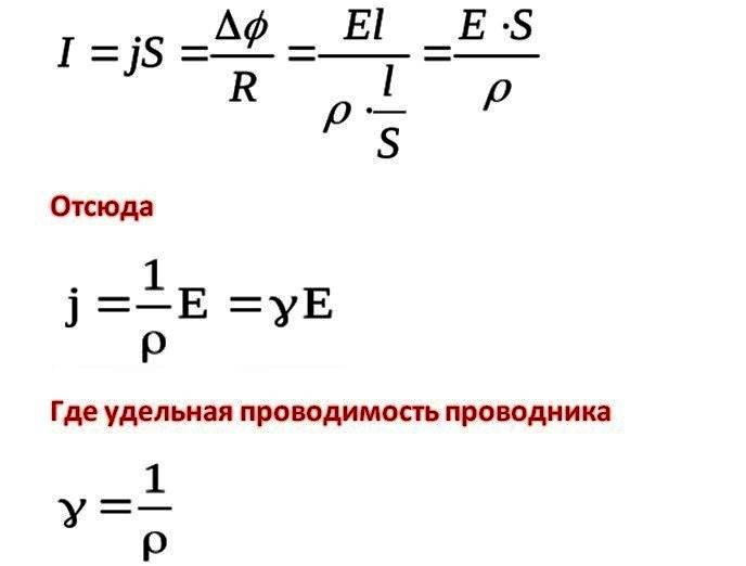 Differential form
Therefore, the expression of the current in vector form will be: j = E.
Important! In the case of metallic conductors, the conductivity decreases with increasing temperature, while for semiconductors it increases. Omov's law does not demonstrate strict proportionality
The resistance of a large group of metals and alloys disappears at a temperature close to absolute zero, and the process is called superconductivity.


