- Power lamps from 12V
- Electronic ballast for fluorescent lamps
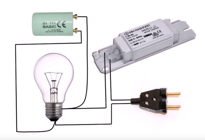
- Classic connection via electromagnetic ballast
- Circuit Features
- Connection order
- First step
- Third step
- Throttle overheating and possible consequences
- How to use it correctly
- Purpose and device of electronic ballast
- Checking fluorescent lamps
- How to connect a fluorescent lamp?
- Connecting a fluorescent lamp to an electronic ballast
- Repair
- Briefly about the features of the lamps
- Principle of operation
- Classification and types of chokes.
Power lamps from 12V
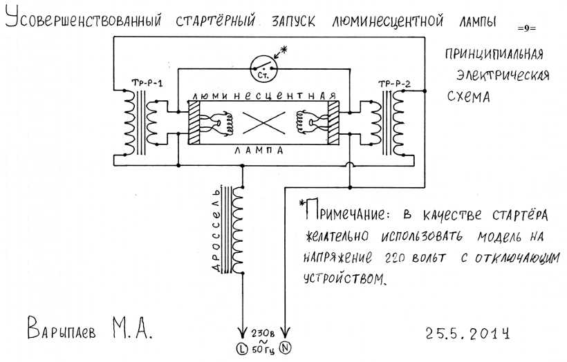
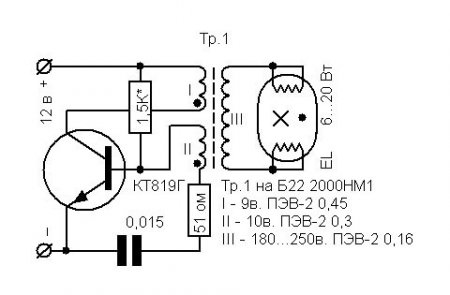
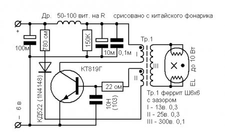
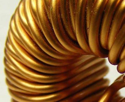
But lovers of homemade products often ask the question “How to light a fluorescent lamp from low voltage?”, We found one of the answers to this question. To connect the fluorescent tube to a low-voltage DC source, such as a 12V battery, you need to assemble a boost converter. The simplest option is a 1-transistor self-oscillating converter circuit. In addition to the transistor, we need to wind a three-winding transformer on a ferrite ring or rod.
Such a scheme can be used to connect fluorescent lamps to the vehicle's on-board network. It also does not need a throttle and a starter for its operation. Moreover, it will work even if its spirals are burned out.Perhaps you will like one of the variations of the considered scheme.
Starting a fluorescent lamp without a choke and starter can be carried out according to several considered schemes. This is not an ideal solution, but rather a way out of the situation. A luminaire with such a connection scheme should not be used as the main lighting of workplaces, but it is acceptable for lighting rooms where a person does not spend much time - corridors, storerooms, etc.
You probably don't know:
- Advantages of electronic ballast over empra
- What is a choke for?
- How to get a voltage of 12 volts
Electronic ballast for fluorescent lamps
Electronic ballast circuits for fluorescent lamps are as follows: On the electronic control board is:
- EMI filter that eliminates interference coming from the mains. It also extinguishes the electromagnetic impulses of the lamp itself, which can negatively affect a person and surrounding household appliances. For example, interfere with the operation of a TV or radio.
- The task of the rectifier is to convert the direct current of the network into an alternating current suitable for powering the lamp.
- Power factor correction is a circuit responsible for controlling the phase shift of the AC current passing through the load.
- The smoothing filter is designed to reduce the level of AC ripple.
As you know, the rectifier is not able to perfectly rectify the current. At the output of it, the ripple can be from 50 to 100 Hz, which adversely affects the operation of the lamp.
The inverter is used half-bridge (for small lamps) or bridge with a large number of field-effect transistors (for high-power lamps). The efficiency of the first type is relatively low, but this is compensated by driver chips.The main task of the node is to convert direct current to alternating current.
Before choosing an energy-saving light bulb. it is recommended to study the technical characteristics of its varieties, their advantages and disadvantages
Particular attention should be paid to the installation location of the compact fluorescent lamp. Very frequent on-off or frosty weather outside will significantly reduce the duration of the CFL
Connecting LED strips to a 220 Volt network is carried out taking into account all the parameters of lighting devices - length, quantity, monochrome or multicolor. Read more about these features here.
A choke for fluorescent lamps (a special induction coil made of coiled conductor) is involved in noise suppression, energy storage and smooth brightness control.
Voltage surge protection - not installed in all electronic ballasts. Protects against mains voltage fluctuations and erroneous start without a lamp.
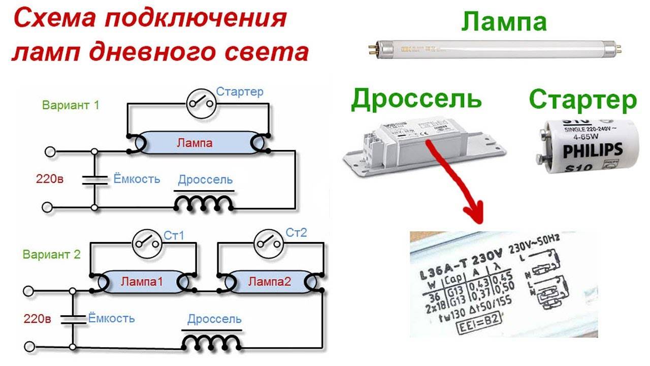
Classic connection via electromagnetic ballast
Circuit Features
In accordance with this scheme, a choke is included in the circuit. Also included in the circuit is a starter.


Fluorescent lamp chokeFluorescent lamp starter - Philips Ecoclick StartersS10 220-240V 4-65W
The latter is a low power neon light source. The device is equipped with bimetallic contacts and is powered by an AC mains supply. The throttle, starter contacts and electrode threads are connected in series.
Instead of a starter, an ordinary button from an electric bell can be included in the circuit. In this case, the voltage will be applied by holding the bell button down. The button must be released after lighting the lamp.
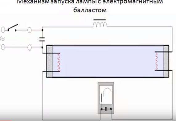
Connecting a lamp with electromagnetic ballast
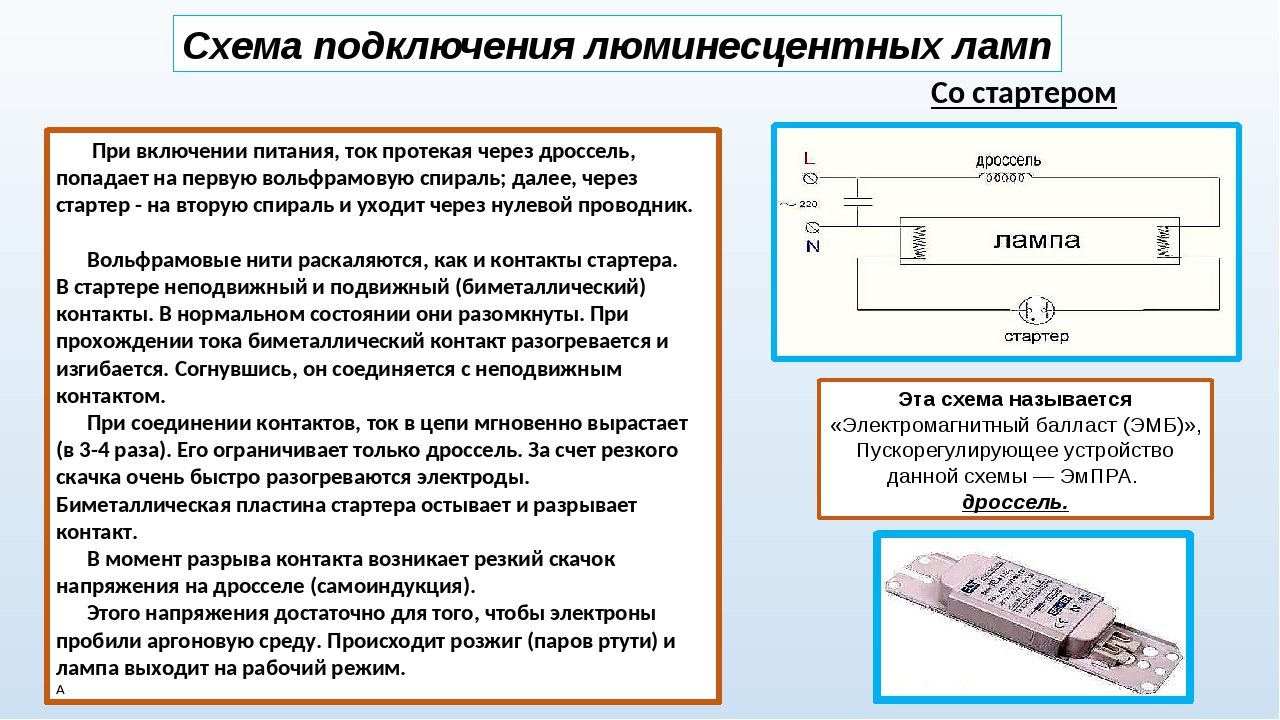
The order of operation of the circuit with an electromagnetic type ballast is as follows:
- after being connected to the network, the choke begins to accumulate electromagnetic energy;
- through the starter contacts, electricity is supplied;
- the current rushes along the tungsten filaments of heating the electrodes;
- electrodes and starter heat up;
- the starter contacts open;
- the energy accumulated by the throttle is released;
- the magnitude of the voltage on the electrodes changes;
- a fluorescent lamp gives light.
In order to increase the efficiency and reduce the interference that occurs when the lamp is turned on, the circuit is equipped with two capacitors. One of them (smaller) is located inside the starter. Its main function is to extinguish sparks and improve the neon impulse.
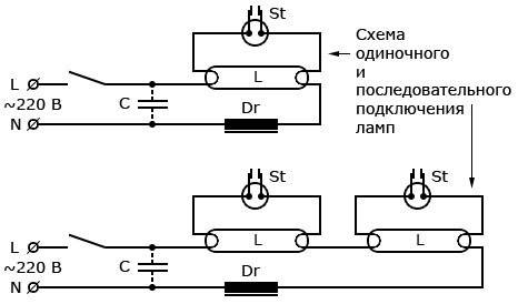
Wiring diagram for one fluorescent lamp through a starter
Among the key advantages of a circuit with an electromagnetic type ballast are:
- time-tested reliability;
- simplicity;
- affordable cost.
- As practice shows, there are more disadvantages than advantages. Among them, it is necessary to highlight:
- impressive weight of the lighting device;
- long turn-on time of the lamp (on average up to 3 seconds);
- low efficiency of the system when operating in the cold;
- relatively high energy consumption;
- noisy throttle operation;
- flickering that adversely affects vision.
Connection order
The connection of the lamp according to the considered scheme is carried out using starters.Next, an example of installing one lamp with the inclusion of a model S10 starter in the circuit will be considered. This state-of-the-art device features a flame-retardant housing and high-quality construction, making it the best in its niche.
The main tasks of the starter are reduced to:
- ensure that the lamp is turned on;
- breakdown of the gas gap. To do this, the circuit breaks after a rather long heating of the lamp electrodes, which leads to the release of a powerful pulse and direct breakdown.
The throttle is used to perform the following tasks:
- limiting the magnitude of the current at the moment of closing the electrodes;
- generation of voltage sufficient for the breakdown of gases;
- maintaining the discharge burning at a constant stable level.
In this example, a 40 W lamp is connected. In this case, the throttle must have a similar power. The power of the starter used is 4-65 watts.
We connect in accordance with the presented scheme. To do this, we do the following.
First step
In parallel, we connect the starter to the pin side contacts at the output of the fluorescent lamp. These contacts are the conclusions of the filaments of the sealed bulb.
Third step
We connect the capacitor to the supply contacts, again, in parallel. Thanks to the capacitor, reactive power will be compensated and interference in the network will be reduced.
Throttle overheating and possible consequences
The use of light bulbs that have expired and various breakdowns periodically occur can result in a fire. How to dispose of used fluorescent devices is described in detail here.


Regular inspection of the condition of lighting devices will help to avoid the occurrence of a fire hazard - visual inspection, checking the main components.
By the end of the lamp life, you can notice a significant overheating of the ballast - of course, you cannot check the temperature with water, for this you should use measuring instruments. Heating can reach 135 degrees and above, which is fraught with sad consequences
If used improperly, the bulb of a mercury bulb may explode. The smallest particles are able to scatter within a radius of three meters. Moreover, they retain their incendiary abilities, even falling from the height of the ceiling to the floor.
The danger is overheating of the inductor winding - the device consists of various types of materials, each of which has its own characteristics. For example, manufacturers impregnate insulating gaskets with complex compositions, the individual elements of which have unequal combustibility and ability to form smoke.
Even seven turns of the throttle, in which a short circuit has occurred, can become a fire hazard. Although a closure of at least 78 turns is a high probability of ignition, this fact was established empirically
In addition to overheating of the throttling element, there are other situations with fluorescent lamps that present a fire hazard.
It can be:
- problems caused by a violation of the manufacturing technology of the ballast, which affected the final quality of the apparatus;
- poor material of the diffuser of the lighting device;
- ignition scheme - with or without a starter, the fire hazard is the same.
It should be remembered that careless connection, poor quality of contacts or circuit components can lead to problems, which most often occurs when using very cheap devices purchased from unknown manufacturers.
Conscientious companies give a guarantee for their products, and the technical parameters of the devices indicated on the case or packaging are true. This fact directly affects the service life of both the ballast itself and gas-discharge light bulbs, the article recommended by us will acquaint you with the features of the device and operation of which.
How to use it correctly
A fluorescent lamp is a small gas discharge device. Due to the design of the lamp, a limiter is required in the network to which it is to be connected. This limiter is the throttle, but first you need to learn how to use it correctly. Before you create an electrical circuit yourself, you need to know that it can have a different look, which depends on such parameters:
- type of connected choke;
- number of lamps and limiters and connection method.
These parameters affect the final form of the electrical circuit and the connection of the inductor. Even with minimal knowledge in electrical engineering, you can easily assemble a simple circuit with several elements
It is important that the connection of all elements is consistent
Note! It is necessary that the power of the lamp be lower than the power of the inductor. Usage example
 Usage example
Purpose and device of electronic ballast
Currently, outdated equipment has been replaced by electronic ballasts for fluorescent lamps, which are electronic ballasts.They provide instant switching on of the lamp, can work with almost any supply voltage, they do not have the disadvantages of the old ballast. Fluorescent lamps are a type of gas-discharge light sources. The standard design includes a glass tube filled with an inert gas and mercury vapor, as well as spiral electrodes located at the edges. There are also contact leads through which electric current flows.


The principle of operation of such lamps is the luminescence of gases when an electric current passes through them. The usual current between the electrodes is not enough to form a glow discharge. Therefore, the spirals are first heated by the current passed through them, and then a pulse with a voltage of 600 V and above is applied.
As a result, the emission of electrons begins from the heated coils, which, together with the high voltage, form a glow discharge. In the future, the current and voltage must be maintained at a certain level, ensuring the normal functioning of the lamp. Compact or energy-saving fluorescent lamps work on the same principle. They differ from standard products only in size and shape.
All types of lamps are powered through a ballast, also called a ballast. In older products, electromagnetic ballast or EMPRA was used. Its design included a throttle and a starter. These devices had a low efficiency, the luminous flux turned out to be pulsating, accompanied by a strong buzz. Serious interference occurred while working on the network.In this regard, manufacturers have gradually abandoned the electronic ballast and switched to more modern and convenient electronic devices (electronic ballasts).
The design of the electronic ballast is made in the form of a board with a high-frequency converter located on it. In these devices, there are no shortcomings characteristic of the EMPRA, so the operation of the lamp has become more stable. It provides the output of an increased luminous flux and lasts much longer.
A standard electronic ballast circuit includes the following parts:
- Diode bridge;
- High-frequency generator based on a half-bridge converter. More expensive products use a PWM controller;
- Dinistor DB3, used as a starting threshold element and rated for a voltage of 30 volts;
- Power LC circuit for glow discharge ignition.
Checking fluorescent lamps
If your lamp has stopped igniting, the likely cause of this malfunction is a break in the tungsten filament that heats the gas and causes the phosphor to glow. During operation, tungsten evaporates over time, starting to settle on the walls of the lamp. In the process, the glass bulb at the edges has a dark coating, which warns of a possible failure of this device.
It is very simple to check the integrity of the tungsten filament, you need to take an ordinary tester that measures the resistance of the conductor, after which you need to touch the probes to the output ends of this lamp. If the device shows, for example, a resistance of 9.9 ohms, then this will mean that the thread is intact. If, during the test of a pair of electrodes, the tester shows a full zero, this side has a break, so the fluorescent lamps will not turn on.
The spiral can break due to the fact that during the time of its use the thread becomes thinner, so the tension that passes through it gradually increases. Due to the fact that the voltage is constantly increasing, the starter fails, which can be seen from the characteristic “blinking” of these lamps. After the burned-out lamps and starters are replaced, the circuit will work without adjustments.
If, during the inclusion of the lamps, extraneous sounds are heard or the smell of burning is felt, then it is necessary to immediately de-energize the lamp, checking the performance of its elements. It may be that slack has appeared on the terminal connections themselves and the wire connection is warming up. In addition, in the case of poor-quality manufacturing of the inductor, a turn-to-turn circuit of the windings may occur, which will lead to the failure of the lamps.
How to connect a fluorescent lamp?
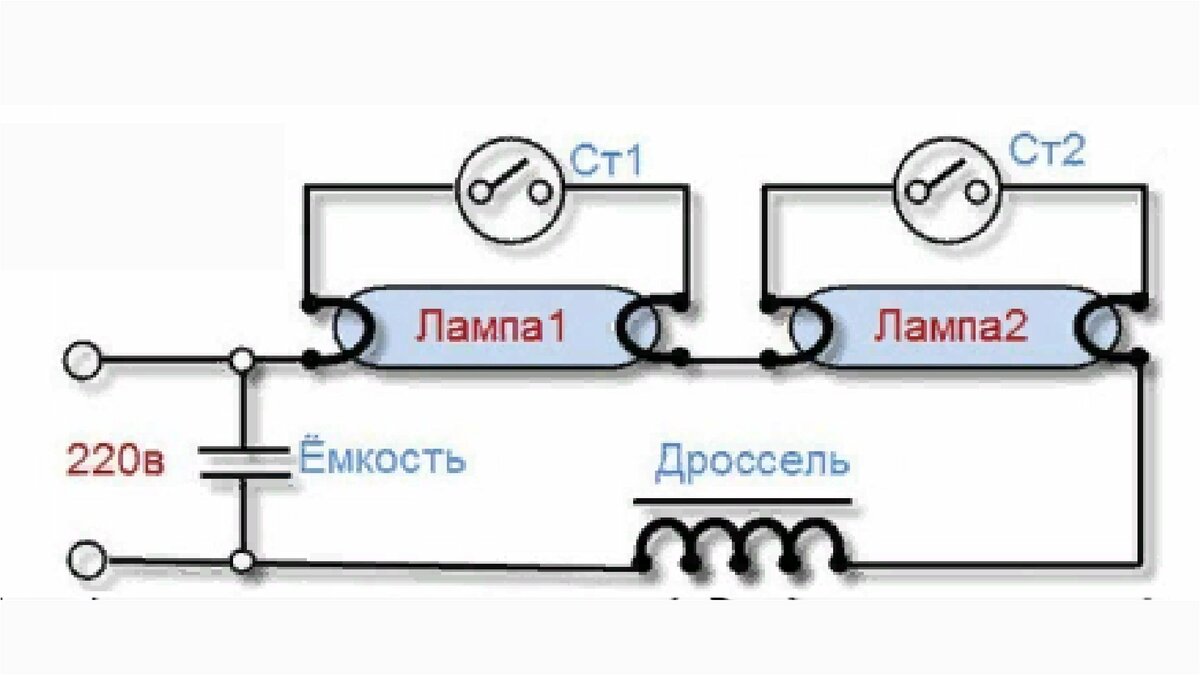
Connecting a fluorescent lamp is a very simple process, its circuit is designed to ignite only one lamp. To connect a pair of fluorescent lamps, you need to slightly change the circuit, while acting on the same principle of connecting elements in series.
In such a case, it is necessary to use a pair of starters, one per lamp. When connecting a pair of lamps to a single choke, it is imperative to take into account its rated power indicated on the case. For example, if its power is 40 W, then it is possible to connect a pair of identical lamps to it, the maximum load of which is 20 W.
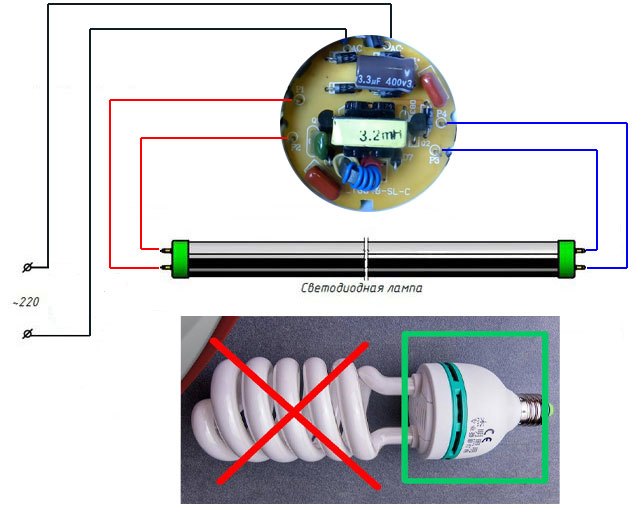
In addition, there is a fluorescent lamp connection that does not use starters.Thanks to the use of specialized electronic ballast devices, the lamp starts up instantly, without "blinking" the starter control circuits.
Connecting a fluorescent lamp to an electronic ballast
Connecting the lamp to electronic ballasts is very simple, because their case contains detailed information, as well as a schematic showing the connection of the lamp contacts with the corresponding terminals. However, to make it more clear how to connect a fluorescent lamp to this device, you can simply carefully study the diagram.
The main advantage of this connection is the absence of additional elements that are needed for starter circuits that control lamps. In addition, with the simplification of the circuit, the reliability of the operation of the entire lamp increases significantly, because additional connections with starters, which are rather unreliable devices, are excluded.
Basically, all the wires that are needed to assemble the circuit come with the electronic ballast itself, so there is no need to reinvent the wheel, invent something and incur additional costs for the purchase of missing elements. In this video clip you can learn more about the principles of operation and connection of fluorescent lamps:
Post navigation
An electromagnetic or electronic ballast for fluorescent lamps is needed for the normal operation of this light source. The main task of the ballast is to convert direct voltage into alternating voltage. Each of them has its pros and cons.
Repair
In the event of a failure of a luminaire with LL, powered by a ballast, along with other elements of the circuit, it is necessary to check the performance of the throttle.In this case, the following malfunctions are possible:
- overheat;
- winding break;
- closure (full or interturn).
To check the throttle, it is necessary to assemble the circuit shown in Fig. 6.
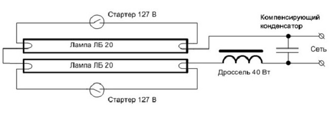
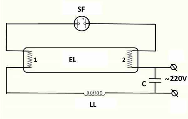


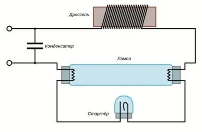

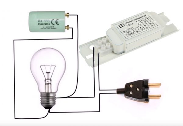 Fig.6. Scheme for checking the throttle
When the circuit is turned on, three options are possible - the lamp is on, the lamp is off, the lamp is blinking.
In the first case, apparently, there is a short circuit in the inductor. In the second case, obviously, there is a break in the winding. In the third case, it is possible that the inductor is intact and it is necessary to look for a malfunction in another element of the circuit. For complete certainty, it is necessary to let the circuit work for 0.5 hours. If at the same time it turns out that the inductor is very hot, then this indicates a short circuit between the turns of the winding.
Briefly about the features of the lamps
The structure of a fluorescent lamp
Each of these devices is a sealed flask filled with a special mixture of gases. At the same time, the mixture is designed in such a way that the ionization of gases takes a much smaller amount of energy compared to ordinary incandescent lamps, which makes it possible to significantly save on lighting.
In order for a fluorescent lamp to constantly give light, a glow discharge must be maintained in it. To ensure this, the required voltage is applied to the electrodes of the light bulb. The main problem is that the discharge can only appear when a voltage is applied that is significantly higher than the operating voltage. However, lamp manufacturers have successfully solved this problem.
Fluorescent lamps
The electrodes are installed on both sides of the fluorescent lamp. They accept voltage, due to which the discharge is maintained. Each electrode has two contacts.A current source is connected to them, due to which the space surrounding the electrodes is heated.
Thus, the fluorescent lamp is ignited after warming up its electrodes. To do this, they are exposed to a high-voltage pulse, and only then does the operating voltage come into play, the value of which must be sufficient to maintain the discharge.
Lamp comparison
| Luminous flux, lm | LED lamp, W | Contact luminescent lamp, W | Incandescent lamp, W |
|---|---|---|---|
| 50 | 1 | 4 | 20 |
| 100 | 5 | 25 | |
| 100-200 | 6/7 | 30/35 | |
| 300 | 4 | 8/9 | 40 |
| 400 | 10 | 50 | |
| 500 | 6 | 11 | 60 |
| 600 | 7/8 | 14 | 65 |
Under the influence of the discharge, the gas in the flask begins to emit ultraviolet light, which is immune to the human eye. In order for the light to become visible to a person, the inner surface of the bulb is coated with a phosphor. This substance provides a shift in the frequency range of light into the visible spectrum. By changing the composition of the phosphor, the range of color temperatures also changes, thereby providing a wide range of fluorescent lamps.
How to connect a fluorescent lamp
Fluorescent type lamps, unlike simple incandescent lamps, cannot simply be plugged into an electrical network. For the appearance of an arc, as noted, the electrodes must warm up and a pulsed voltage should appear. These conditions are provided with the help of special ballasts. The most widely used ballasts are electromagnetic and electronic types.
Principle of operation
The basic principle of operation of the device is the phase shift of the alternating current during the zero crossing by ninety degrees. Due to this bias, the required current is maintained so that the metal vapor in the lamp can burn.
 Designation of an inductor in a circuit.
The designation of the inductor in the connection circuit looks like the cosine of the angle phi.This is the same value by which the current lags behind the voltage. The number by which the current remains behind the voltage is often called the power value or coefficient. In order to find active power, it is necessary to multiply the voltage value, the strength of the alternating current and the power factor.


If the power value is small, then this will lead to an increase in reactive energy, which in turn will create an additional load on the conductive cable wires and transformers.
In order to increase the value of the cosine phi, a compensation capacitor is also connected in parallel to the device itself in the operation circuit of the luminescent device. So, when connected to the operating circuit of a lamp, the power of which is from 18 to 36 W, a capacitor with a capacity of 3-5 microfarads, the cosine phi will increase to 0.85. The noise of the inductor, which operates at a frequency of 50 Hz, can be of varying intensity.
Inductors according to noise intensity are of the following levels:
- H-level (medium intensity);
- P-level (low intensity);
- C-level (very low intensity);
- A-level (especially low intensity).
To avoid premature failure of luminaires, it is necessary to pay attention to the fact that their power corresponds to the rated power of the inductor
Classification and types of chokes.
Chokes can perform different functions in different circuits. Suppose in the circuit of an illuminator on a fluorescent lamp it has one task, in electronics with the help of a coil it is possible, for example, to decouple different-frequency electronic circuits, or use it in an LC filter. This is what determines the classification.
The type of inductor depends on its purpose in each particular circuit.It can be filtering, smoothing, network, motor, special purpose. In any case, they are united by a common property: high resistance to alternating current and low resistance to direct current. This can achieve a reduction in electromagnetic interference and interference. In single-phase circuits, the inductor can be used as a limiter (fuse) against voltage surges. The choke performs the smoothing function in the rectifier filters. Usually an LC filter is used.


