- Varieties of switches for home use
- Touch light switch works by itself
- Remote switch design
- 2 Illuminated switch structure
- How to connect a backlit device: step by step instructions
- Peculiarities
- Connection
- How a backlit switch works
- Technical features
- LED lights
- What to do if the switch needs to be moved
- Switch transfer - step by step instructions
- Prices for popular models of wall chasers
- Prices for popular types of putty
- Device and principle of operation
- Types of switches depending on the type of backlight
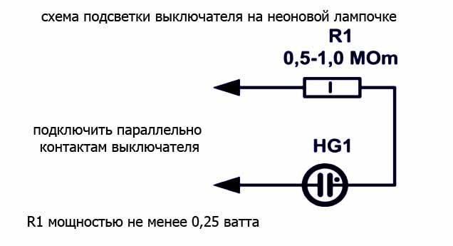
- Illumination using a neon lamp
- Preparing for installation
- Device and principle of operation
- Conclusion
Varieties of switches for home use
Each manufacturer produces different models of switches, which differ both in shape and in internal structure. Nonetheless, several main types should be distinguished.
Table 1. Types of switches according to the switching principle
| View | Description |
|---|---|
| Mechanical | Devices that are easy to install. Instead of the usual button, some models have a lever or cord. |
| Touch | The device works at a touch of a hand, and it is not required to press a key. |
| With remote control | This design is equipped with a special remote control that comes with the kit or a sensor that reacts to movements around. |
The most popular is the first option, which is installed everywhere. Moreover, such switches have become in demand from the very beginning of the appearance of the electrical circuit. The second option is less popular, especially in our country. The third option is a modern model, which is gradually replacing outdated switches from the market.
Motion sensor installation into the design is expedient both in terms of energy savings and home security. For example, if you install a structure at the entrance, then the residents will notice if intruders get into the apartment.
Switch with additional illumination
According to the design features, there are devices with one or more keys (on average, switches with two or three buttons are used for standard electrical appliances). Each button is responsible for turning on and off a separate circuit.
So, if several lamps are installed in one room at once: the main chandelier, spotlights, sconces, then it would be advisable to install a structure with three buttons.
In addition, no less popular are devices with two buttons, which are installed in all apartments without exception. Most often they are needed for a chandelier in the presence of many light bulbs.
According to the installation method, there are internal and external switches. The first option is installed in the apartment, because such structures look aesthetically pleasing. For safety during installation, a special box is installed, which is called a socket box.
Wiring diagram
Recessed switches are used when there is electrical wiring hidden in the wall. Overhead devices are mounted in the presence of external conductors. In this case, the connection scheme has no fundamental differences.
Where is the switch installed?
Touch light switch works by itself
 Connecting a touch light switch
It often happens that touch switches work without pressing. In this case, you need to carefully inspect the device. Perhaps the reason is the closure of contacts.
If the touch panel itself is damaged, you need to seek help from specialists. If they do not fix the problem, you will have to change the device to a new one.
When working with touch switches, a number of precautions must be observed:
- The devices should be connected to the network in such a way that the phase is switched, and not zero.
- If the power supply is operated using a ground wire, it must be connected to the appropriate terminals.
- If during the installation of the switch a wire with many strands was used, the ends must be crimped and tinned. Otherwise, the contact will be broken and the connection will overheat.
It is important that the load matches the parameters of the switch
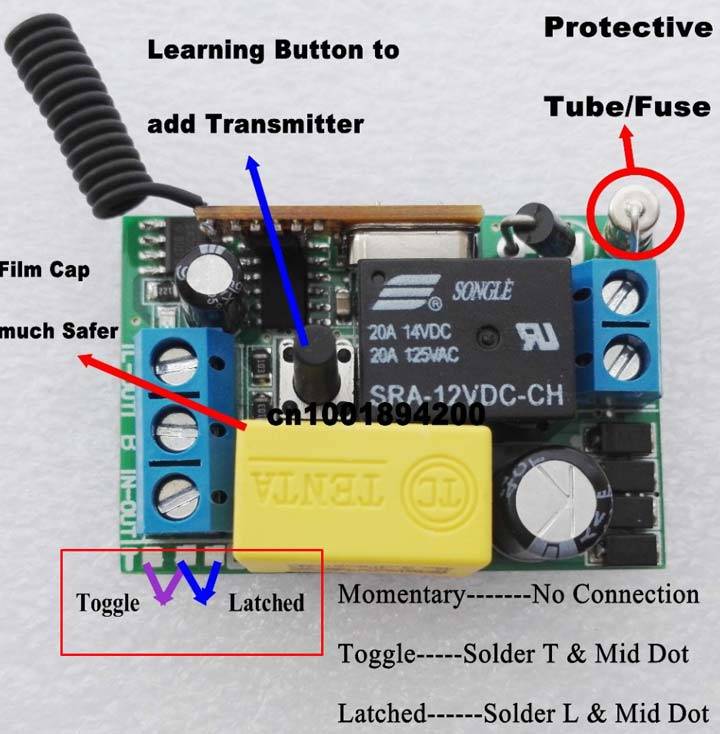
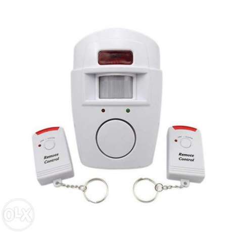
Remote switch design
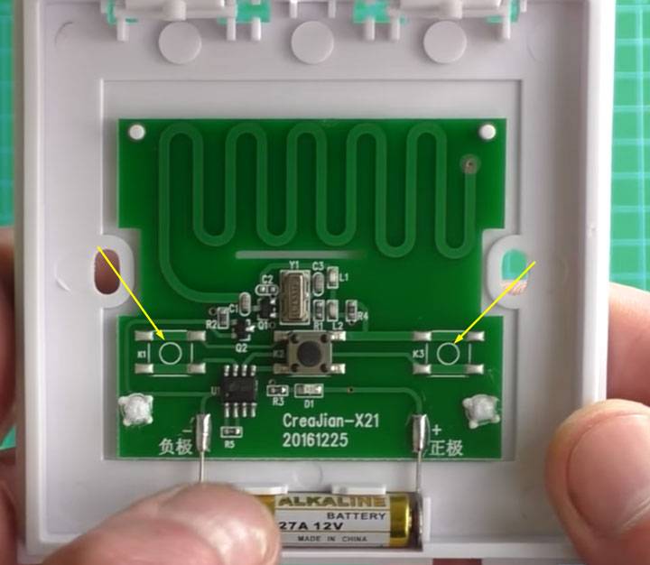
The switch is very easy to take apart. It is enough to pry the slots at the junction of the cover and the body with a screwdriver. No screws need to be unscrewed.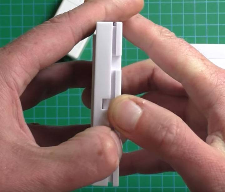
Inside it is:
electronic board
central on/off button
LED for visualizing the binding of the switch and the radio module
battery type 27A for 12 volts
This battery, even with intensive use, can last from 2 years or more. In addition, there is no particular shortage in them at the moment.It may not be included in the package, keep in mind.


By the way, the switch is initially universal. On the sides of the central button, there are places where you can solder two additional buttons.
And by changing the key itself, you can easily get from a single-key - two or even three-key.
True, in this case, you will have to add more modules, according to the number of buttons.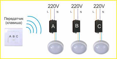
There is a hole on the radio module box. It is intended for a button, when pressed, you can "bind" or "unbind" a particular device.
According to the range of the radio signal, the manufacturer declared a distance of 20 to 100 meters. But this applies more to open spaces. From practice, we can say that in a panel house, the signal easily breaks through four concrete walls at a distance of 15-20 meters.
There is a 5A fuse inside the box. Although the manufacturer indicates that through a remote switch you can connect a load of 10A, and this is as much as 2kW!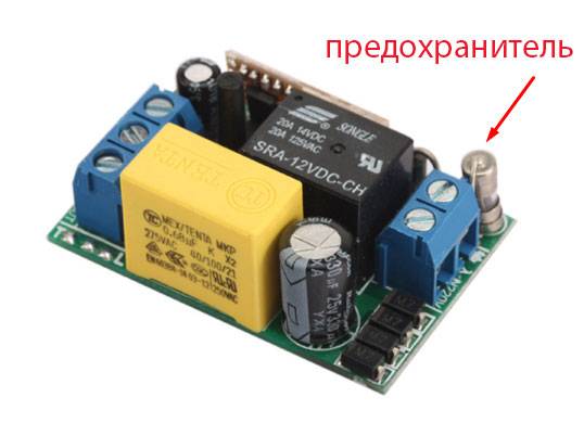
The wiring diagram for connecting the wires to the contacts of the radio module of the wireless switch is as follows: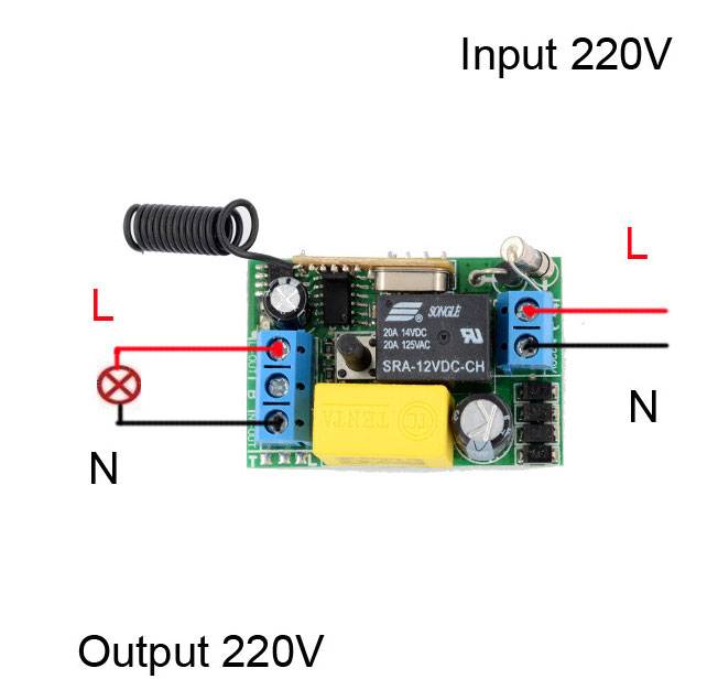
When connecting, you can also focus on the inscriptions. Where there are three terminals - the output, where two - the input.
L out - phase output
N out - zero output
Connect the wiring going to the light bulb to these contacts. For two contacts with another side supply voltage 220V.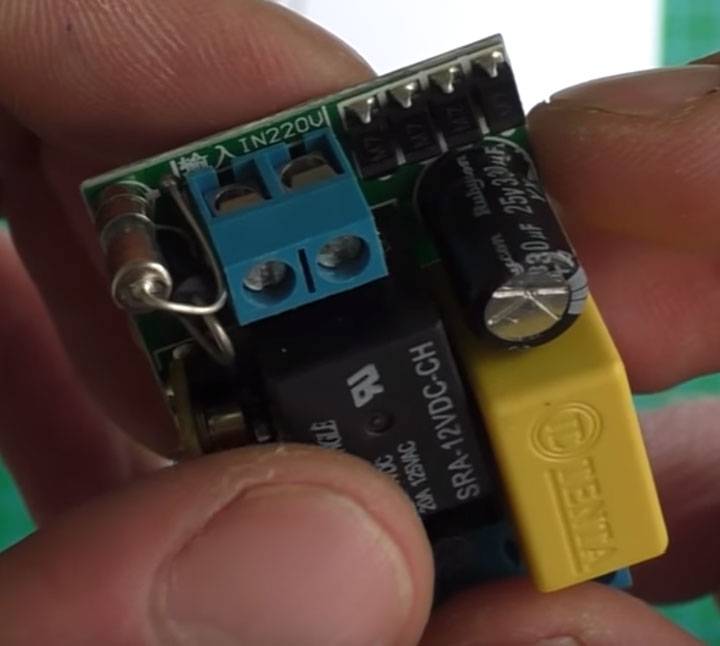
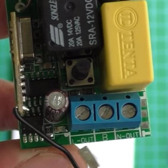
On the side of the output contacts there are three more solder points for jumpers. By soldering them accordingly (as in the figure), you can change the logic of the product:
 This can be used to make a call or to give a short signal. There is also a middle contact "B". When used, the switch will operate in inverse mode.
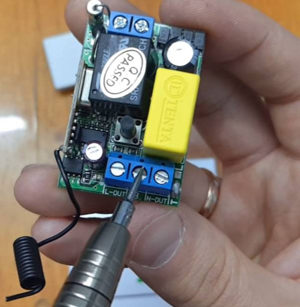
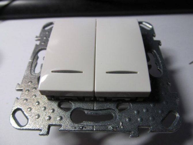
2 Illuminated switch structure
Such a device is not so difficult to connect, as it seems at first glance, but you still need to be careful. You need to choose only high-quality equipment, but in extreme cases, you can work with what you have.
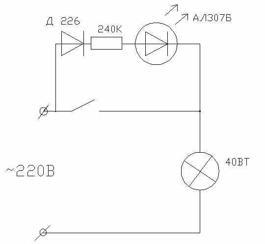
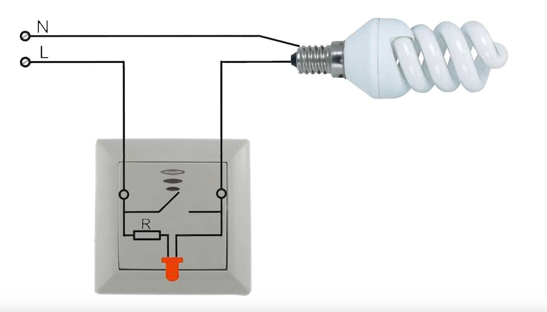
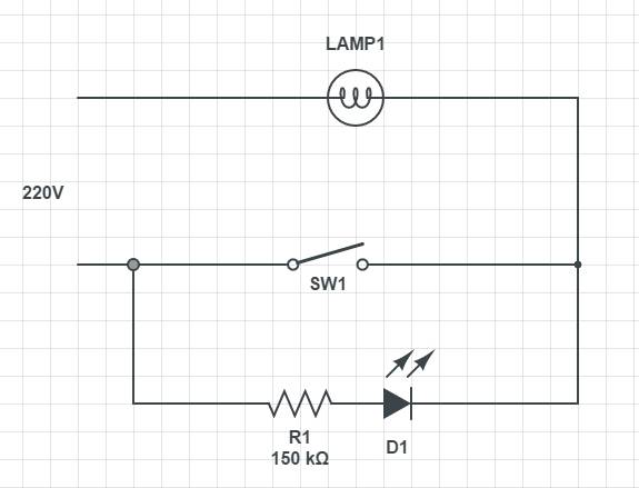
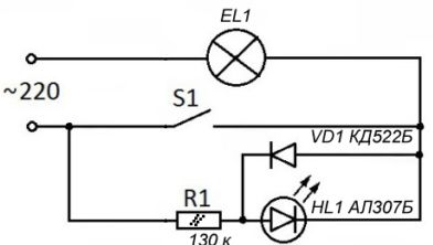
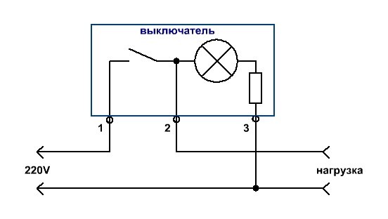
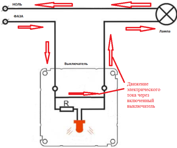
For the backlight, as a rule, a neon light bulb or an LED connected in parallel with the switch contact is responsible. And since the connection is parallel, it means that the indicator light works 24/7, regardless of whether the device is working or not.
It turns out that when the lighting is off, but when the backlight is on, the current passes through the current-limiting resistor, from there it goes to the indicator light, then to the light bulb through the connection terminals and at the end to the neutral, overcoming the path through the incandescent filament.
When the lighting is on, the backlight circuit connected in parallel with the common circuit is shunted with a closed contact. Because it has much less resistance than the backlight circuit, this causes the indicator light to turn off.
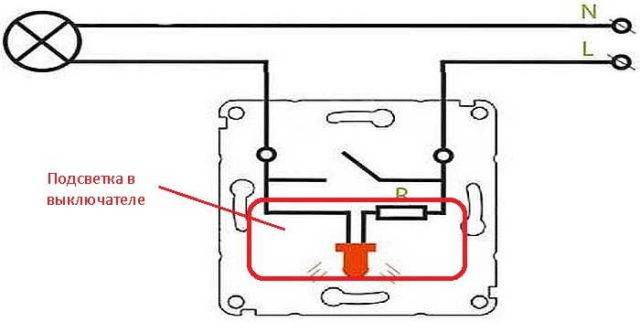
The general scheme of how the backlight works in such a device
The above current limiting resistor is connected in series, its task is to reduce the current to an acceptable value. Since both types of light bulbs require different amounts of current, resistors that are different from each other are placed.
| Light indicator type | Dissipated power, W | Resistance |
| Light-emitting diode | 1 | 100-150 kOhm |
| neon light bulb | 0,25 | 0.5-1 MΩ |
Connecting through a resistor to an LED backlight is not an ideal output, and there are reasons for this.
- 1. The resistor is heated, and quite strongly.
- 2.There is a possibility of reverse current, which can ruin the operation of the LED.
- 3. Devices with LED light bulb consume more than 300W per month.
How to connect a backlit device: step by step instructions
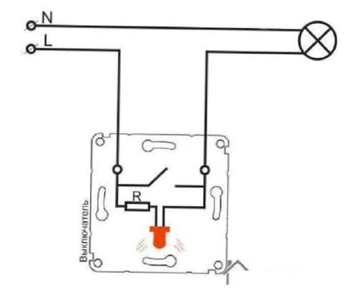
So, the main axiom, which is characteristic, in fact, for the installation of any switch, is as follows: only a phase wire is connected to the light opening device. This is indicated in the Electrical Installation Rules (PUE). Otherwise, if the power line is connected to the chandelier, and the neutral wire is connected to the switch, the person changing the lamps in the lighting device may be shocked.


The process of connecting the described backlit node also differs little from the installation algorithm of a conventional switch. Let's take it as a guide.
It is assumed here that the universal cup is already installed in the socket for the device and the wires are connected.
The scheme of laying wires and connecting them to the switch terminals is not subject to availability lights in it
Here's what the instructions look like.
- First, turn off the power supply in the apartment panel - this is strictly necessary.
-
Then remove the keys from the installed device. To do this, they are gently pry from the side with a screwdriver with a thin sting.
-
Hands pull out the front plastic socket for lining.
- After these manipulations, we have before us the mechanism of the device, which has jagged metal antennae on the back sides for mounting in the socket.
-
The bare end of the power wire is inserted into one of the contacts and the screw is tightened. The same is done with the outgoing link - they fix in it a line coming from the lamp of the room. The order of connecting the wires in this case does not matter.
-
Next, insert the filling of the device into a glass inside the wall and tighten the screws with a screwdriver that press on the antennae. The latter also fix the switch in the glass.
- At the final stage, install the front panel and the keys back.
- Turning on the machine in the shield, check the operation of the switch. When the circuit is open, the backlight should be on.
If, after completing the work, it turned out that the backlight of the device is not lit, it is necessary to dismantle the switch, proceeding in the reverse order, and check its serviceability with a multimeter. But we will talk about the diagnostics and repair of a backlit device in a special section of the article.
As for switches with several keys and an illuminating light bulb, all of the above is also characteristic of them. Regardless of the number of keys, the lighting circuit always has the arrangement already described.
There are also remote control devices. They have a so-called receiving point, which is mounted in the room. The main control circuit may be located in the shield. The receiver looks like a normal switch. It can also be backlit. Its installation is carried out by a professional electrician in accordance with the instructions supplied with the product.
Peculiarities
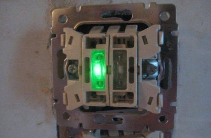
I believe that you have already personally seen, or at least a photo of a backlit switch, because when I was a child, we had such switches in our apartment. An old, Soviet model of a backlit switch, in which a small red light was located on top, and was hidden behind matte, barely transparent, plastic. Apparently, the idea was taken from grandparents, because they had exactly the same switches in the house, or they were installed at the same time.

In any case, as personal experience shows, it is very convenient. At that time, no one had heard of pass-through switches, and therefore, in the middle of the night, one had to navigate in space from memory. Or rather, I would have to, because I was lucky, and there were such switches in the house. In complete darkness, they gave enough light to understand where you are, and, in fact, where the switch is.

Connection
After studying the design of the circuit breaker, you can directly connect the circuit breaker. For those who first encountered such a task, it is recommended to draw up a diagram in advance, according to which wires will be laid to the switch and lighting fixtures.
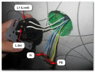
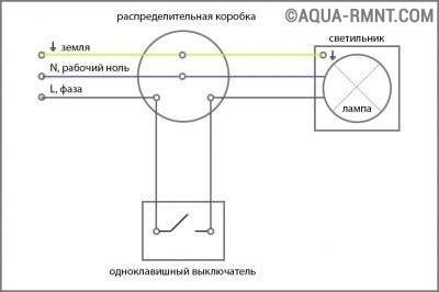
The standard wiring diagram includes a phase wire that is energized. It is indicated by the letter L and is connected to the lamp through the switch. In addition to it, there is a neutral or neutral wire N, which is connected directly to the lamp socket. If there is a ground wire, it is also connected directly to the luminaire.
Wires can be laid in a closed or open way, if this is provided for by the wiring diagram. In the first case, a strobe device in the walls will be required, in the second - corrugated pipes or cable channels. With hidden wiring under the switch, a hole is drilled in the wall.
In order to ensure a reliable connection and high-quality contact with the terminals, the end of each conductor is stripped by about 1-1.5 cm. When using stranded wires, it is recommended to crimp their ends. Three wires are connected to the two-gang switch.The first is phase and is fed to the input, and the second and third go to the output and are brought directly to the lamp. Zero and ground conductors are connected to the contacts of the light sources. The place of input of the phase wire is indicated by an arrow inside the switch. The phase itself is determined by the tester.
After all the wires are installed in their places and done connection of a double illuminated switch, it is necessary to isolate potentially dangerous places. Then the whole structure, together with the wires, is installed in the mounting box and fixed with braces using screws. Upon completion of the main work, you need to install the decorative panel and both keys in place.
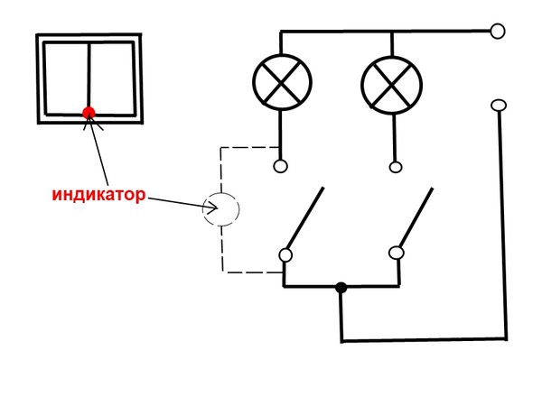
If there is a backlight, to connect a double switch, you must use additional wiring connected to mini-indicators mounted on the keys. One of them is connected to the phase at the input at the top, and the other is connected to one of the wires going to the fixtures. When the light is turned off, the colored indicators will continue to glow on each key.
How a backlit switch works
The main difference between the backlit device from classic models - the presence of an indicator. It can be a neon light bulb or an LED.
The light/indicator switch will not work with the following types of devices:
- fluorescent lamps;
- lighting devices with electronic starting regulators;
- some types of LED lamps.
By functionality, devices are distinguished with one-, two-, three- and four-key, cord and push-button, etc.


Illuminated switches have many advantages:
- Design and construction almost do not differ from standard devices.The only difference is the presence of a LED on the front panel, which makes being in a dark room more comfortable.
- Most schemes are economical. Built-in indicators consume very little electricity.
- Maintenance of the LED does not require large energy costs.
Often, backlit devices are installed in bedrooms. A working backlight helps you quickly navigate the room when you suddenly wake up.
Technical features
These parts reduce their resistance as the temperature increases, compared to metal components. Unfortunately, this has disadvantages - the current strength can increase to uncontrollable levels. The same happens with heating, respectively, after a while after working in such a peak, the diode fails.
Also, such a part is highly sensitive to an increase in voltage, so even the smallest impulse can break it. Accordingly, the manufacturer must select the resistors as accurately as possible. Moreover, the diode can break if the voltage is reversed. It should be noted that this component can only cope with the passage of current in positive sequence.
Even with these shortcomings, switches with diodes are in demand.
LED lights
Often there is a backlight from the LED, which is a semiconductor device that emits light when an electric current flows through it.
The color of a light emitting diode depends on the material it is made of and to some extent on the applied voltage.LEDs are a combination of two semiconductors of different types of conductivity p and n. This compound is called an electron-hole transition, it is on it that light emission occurs when a direct current passes through it.
The appearance of light radiation is explained by the recombination of charge carriers in semiconductors, the figure below shows an approximate picture of what is happening in the LED.
Recombination of charge carriers and the appearance of light radiation
In the figure, a circle with a “-” sign indicates negative charges, they are in the green area, so the area n is conventionally designated. The circle with the “+” sign symbolizes positive current carriers, they are in the brown zone p, the border between these areas is the p-n junction.
When, under the action of an electric field, a positive charge overcomes the p-n junction, then right at the border it combines with a negative one. And since during the connection there is also an increase in energy from the collision of these charges, part of the energy goes to heat the material, and part is emitted in the form of a light quantum.
Structurally, the LED is a metal, most often a copper base, on which two semiconductor crystals of different conductivity are fixed, one of them is the anode, the other is the cathode. An aluminum reflector with a lens attached to it is glued to the base.
As can be understood from the figure below, a lot of attention is paid to heat removal in the design, this is no coincidence, since semiconductors work well in a narrow thermal corridor, going beyond its boundaries disrupts the operation of the device up to failure.
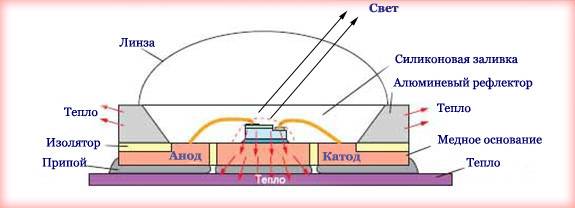
LED device diagram
In semiconductors, with increasing temperature, unlike metals, the resistance does not increase, but, on the contrary, decreases. This can cause an uncontrolled increase in current strength and, accordingly, heating, when a certain threshold is reached, a breakdown occurs.
LEDs are very sensitive to exceeding the threshold voltage, even a short pulse disables it. Therefore, current-limiting resistors must be selected very accurately. In addition, the LED is designed for the passage of current only in the forward direction, i.e. from the anode to the cathode, if a voltage of reverse polarity is applied, then this can also disable it.
And yet, despite these limitations, LEDs are widely used for illumination in switches. Consider the circuits for switching on and protecting LEDs in switches.
What to do if the switch needs to be moved
In some situations, there is a desire or need to move the switch to another location. For example, when there are children in the family who have already grown up, but still cannot reach the top switch. Therefore, according to the rules for installing electrical equipment, it is allowed to move the device to another location.
Benefits of self-replacing the circuit breaker
It is allowed to mount the switch at a distance of 82 to 165 centimeters from the floor level. However, in order to start moving equipment, you must first determine the exact location of its installation. It is recommended to place the switch at a distance of no more than 25 centimeters from the door jamb (the side does not matter, but more often the device is placed on the right).


 It is allowed to mount the switch on each side of the door
Switch transfer - step by step instructions
Step 1. If you transfer equipment within 100 centimeters from the existing position down or up, then a strobe is made in the ceiling. As a rule, it has a depth of 2 times the cable cross-section in the corrugation. So, the wire should not stick out of the opening. You can prepare such a recess with a puncher or a special tool for strobes.
Prices for popular models of wall chasers
wall chaser
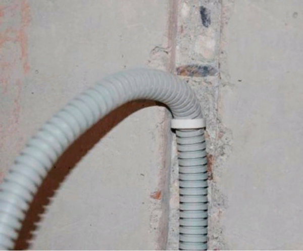 It looks like a strobe in the ceiling for the cable
Step 2. Now directly at the installation site new switch, you need to make a recess for the mounting bowl. This is done using the same perforator and a special round nozzle. If the wall is concrete, then the depth of the opening will be about 50 millimeters, and if it is brick or panel, then 45 millimeters. The diameter of the nozzle itself will be about 7 centimeters (selected individually).
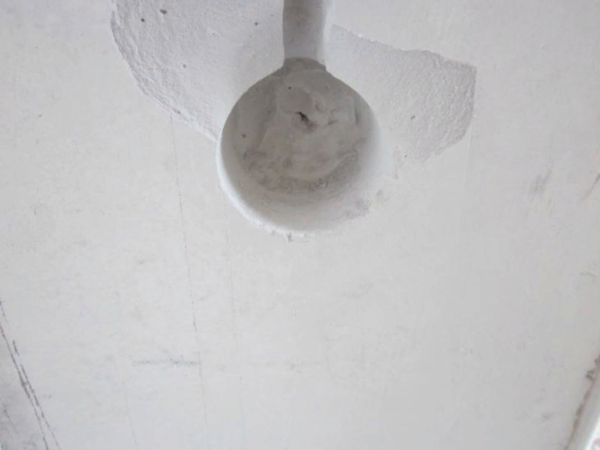 This is what the opening for the mounting bowl looks like
Step 3. Now you need to completely de-energize the apartment and dismantle the old switch (in the way that we discussed above). Only here, in addition to the switch, the mounting bowl is dismantled from the wall. To do this, you need the same impact device or a hammer with a flat screwdriver. Most often, socket boxes are fixed on a gypsum mortar, which begins to crumble upon impact.
In this case, it is important not to violate the integrity of the plastic base.
It is necessary to carefully remove the mounting bowl from the wall
Step 4. Now you should increase the cable to the required length. Wires, as a rule, are connected with special clamps or a block, but if this is not possible, then their ends are twisted and then insulated.According to the installation rules, the cable must be in a special plastic corrugation with a diameter of about 1.6 centimeters. It is also necessary to wrap with insulating tape the junction of the two parts of the corrugation. When extending the cable, leave a few centimeters in reserve.
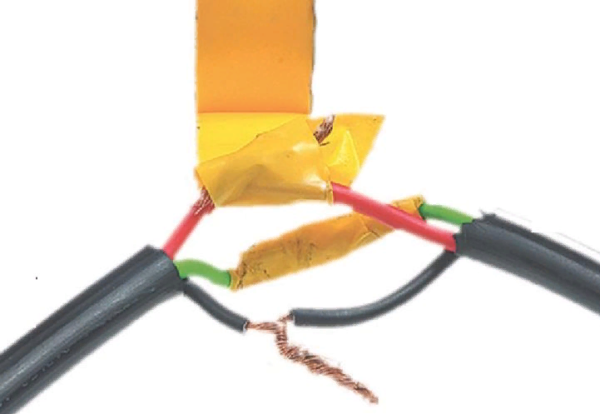 There should be no open wires, so they are wrapped with insulation tape
Step 5. Now you need to install the mounting bowl in a new opening, it will be easier to fix it using alabaster, which contains gypsum. Since the gypsum begins to harden in just a few seconds, it is quickly diluted with water according to the instructions, and then the hole is covered up.
 It is necessary to work with alabaster quickly, until it has time to harden.
Step 6. It is necessary to cover the strobes in the ceiling with the solution. In this case, the wiring should be laid by all rulesbecause you can't change its location. Then the surface of the wall must be finished with a finishing putty in order to finally hide the location of the strobe. When the surface dries, it is treated with fine-grained sandpaper.
Prices for popular types of putty
Putties
 Strobes should also be puttied
Connect the switch only after the mortar has hardened. Therefore, you will have to wait a few hours.
If you plan to move the switch a significant distance from its original location, then most likely it will need to be connected to another box. In this case, it is advisable to seek help from an experienced electrician.
Device and principle of operation
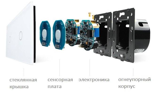
The touch switch consists of four main elements:
- frame;
- electronic board (switch);
- protective panel;
- touch sensor.
The touch sensor transmits a signal (touch, sound, movement, signal from the control panel) to the electronic board. In the switch, the oscillations are amplified and converted into an electrical impulse, which is enough to close / open the circuit - turn the device on and off. It is possible to smoothly apply the load, which regulates the brightness of the lighting. This is due to the duration of the touch. Such switches are equipped with a dimmer.
Savings on electricity will come from dimming the lighting power.
Types of switches depending on the type of backlight
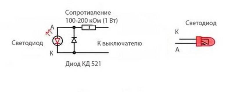
You just need to purchase a regular switch and indicator.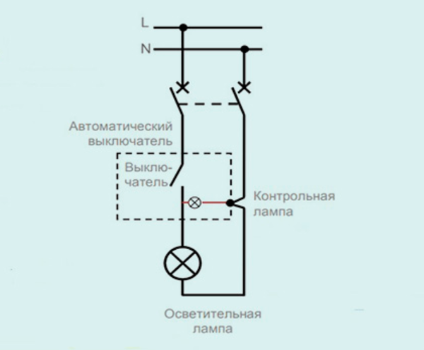
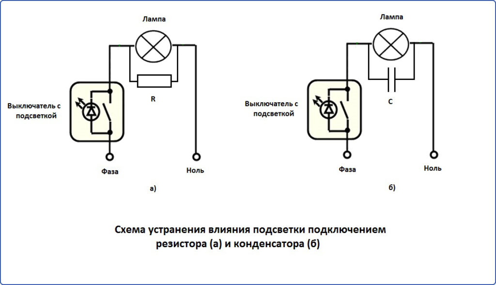
With them, a resistor is soldered into the circuit, with its help the mains voltage is reduced to a minimum value.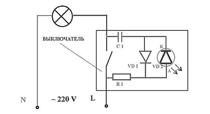
Capacitor Switch LED Illumination Circuit To increase the level of illumination by an order of magnitude, a capacitor can be used. When the equipment is turned off, a current flows through the resistor, which goes further and turns on the LED.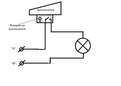
In addition to the LED, the circuit has a current-limiting resistor. When resistors of the same resistance are connected in parallel, the power is calculated as in serial connection, and the value of each resistor should be equal calculated value multiplied by the number of resistors connected in parallel.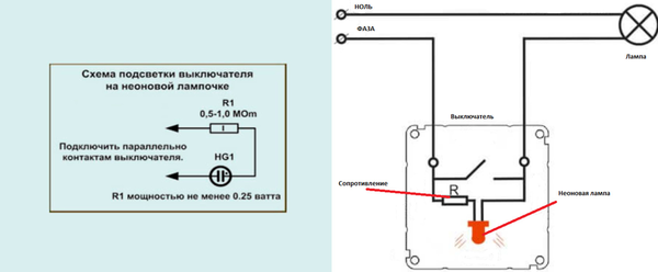
For example, consider how to set the indication on a single-gang switch. DIY lighting The simplest wiring diagram for a switch with an LED is as follows. This is what the assembled circuit looks like. A distinctive feature of such switches is the way they are mounted: they installed on different walls in the room, but only one light source is connected.


Illumination using a neon lamp
In appearance, this device is a resistor with a neon lamp. Scheme of the device device The presented device differs from a conventional switch only in the presence of a special illuminating indicator, which can act as neon lamps or the same LED containing a limited resistor. In order to properly mount the new switch, you must follow the same scheme as when removing it, only in reverse order, that is: Insert the inner part into the socket, having previously connected the wires to it.
Below you can see the photo of the presented types of switches with backlight. With this connection the circuit current will be calculated based on the needs of the lamp, exceeding the needs of the LED by hundreds of times. Depending on the shape and size of the housing, determine the installation location of the LED. Then, at the outputs, the black wires must be connected to the input terminals of the second switch. Application of the LED switch The switch equipped with illumination is installed where it is dark even in the daytime, and the constant use of the lighting device is impractical.
The load current will follow the path of least resistance and the LED will turn off. Sequence of actions: Turn off the switch and de-energize the room. It is impossible to spoil anything when installing the backlight in the wall switch, as the lamp itself is a current limiter.
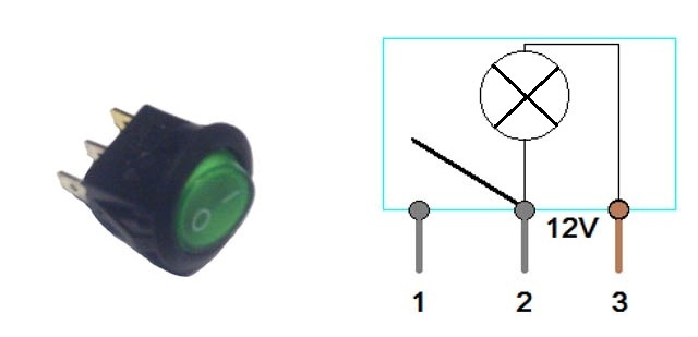
Installation of 1 illuminated rocker switch
Preparing for installation
At the preparatory stage draw up a power supply diagram for lighting devices with a detailed location of all batteries, spotlights, tapes and switches.It is convenient to carry out this procedure on the factory plan of the cabinet, which is supplied with it. Then transfer the diagram to the cabinet frame, mark the equipment installation points, cable laying.
To perform the work, you will need some materials and tools that should be prepared in advance:
- LED strips or spotlights;
- wires for power - are selected in accordance with the power consumption;
- power supply for connecting cabinet lighting equipment for 12 V;
- controller for connecting RGB tape;
- light box for organizing closed LED strips;
- terminal connectors, solder and flux to connect the electrical connection;
- key switch, button or control panel for switching the cabinet lighting.
Of the tools you need drill with nozzles for designing round holes in wardrobes or kitchen cabinets. Screwdriver or screwdriver for working with fasteners, construction stapler, soldering iron. Locksmith tools - pliers, wire cutters, stationery knife, scissors, etc. If you have everything you need, you can proceed directly to the installation of the backlight.
Device and principle of operation
Any double switch consists of the following structural elements:
- Two keys that can change position depending on the actions performed.
- The plastic case removed from the device before connection.
- Terminal blocks for connecting input and output conductors.
In some models, the terminal blocks are replaced by screw terminals. The first option is considered more reliable, so it is used in all modern products.Screw terminals loosen gradually and require periodic tightening to restore normal contact.
Inside the switch there is an input phase wire and output wires connected to lighting fixtures. Closing and opening of contacts on each of the terminals is carried out independently of each other. Due to this, one, two or several lamps can be turned on at once. It is recommended to apply voltage at help of stranded wires.
Work switch for two key is to use various options for switching on and off, allowing you to create the required level of illumination:
- Option number 1. One key is turned on, and in this position the voltage is supplied to one light bulb or a separate group of lamps.
- Option number 2. The second switch key is activated, supplying voltage to two light bulbs or a group of fixtures with a different number of lamps. Such switching makes it possible to change the lighting in the room when necessary.
- Option number 3. Both keys turn on, all lighting devices start working, providing maximum lighting.
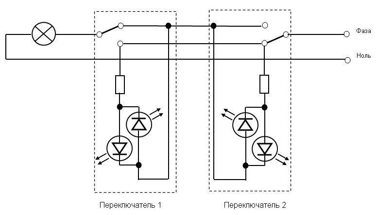
In many modern switches, the backlight is connected. It is a neon light bulb or LED connected in series with a current limiting resistor. This chain is connected in parallel with the switch contact. Regardless of the position of the keys, it will remain energized all the time.
Thus, when the lighting is off, the following chain is obtained: the phase voltage passes through the current limiting resistor, then through the LED and the connection terminals, the current enters the lamp and goes through the filament of the incandescent lamp to neutral.In this position, the backlight is always on. When the light is turned on, the contact closes and shunts the circuit. Since it has a very low resistance, the current stops flowing through the backlight, but begins to flow through the contact. In this case, the LED does not light up at all or glows barely noticeable.
Conclusion
By connecting a similar device to the lighting system of a kitchen or any other home, you will get significant advantages in terms of light control. Turning on the light with a light touch, minimizing energy consumption and comfort - all this will give you a touch switch connected to the LED strip.
 Choosing the Right Autonomous motion sensors with siren
 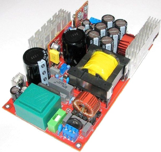 Handmade power supplies
 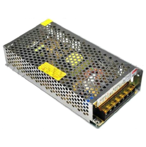 Schemes for homemade blocks LED strip power supply
  How to choose a motion sensor for a toilet How to choose the right radio light switch with a remote control for your home, how to connect Details of calculating the power of a power supply for LEDs


