- Mounting the hood with your own hands. Work order
- Ventilation Requirements
- Required machine power
- Acceptable concentration method
- Embedded
- Types of residential buildings
- Is it necessary to ventilate a boiler room in a private house, and why?
- The main rules and requirements for ventilation of the boiler room in accordance with SNiP (+ video)
- Air exchange calculation with formula and example (+ video with more detailed explanations)
- 7.2 Calculation of the air flow rate removed by local exhausts and ventilated ceilings
- What to consider at the design stage?
- Ventilation for the boiler: its parameters and scheme
- Law
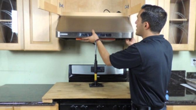
Mounting the hood with your own hands. Work order
After the hood is selected and the place for it is determined, you can proceed to the preparatory and installation work.
To install the hood, you need to purchase pipes. Experts recommend opting for plastic round sections with a diameter of 125 mm
It is important to understand that square and rectangular ones look more attractive and are easier to install, but the most important thing for which work is being done is a good exhaust air outlet, and the best draft will be in a round pipe. You can also purchase metal pipes, but they are:
- Will cost more.
- They will be more difficult to install.
- Will be noisier during ventilation operation.
Be careful with corrugated pipes. They are noisy and unattractive.
You should not choose sewer pipes either - they do not meet the requirements for an exhaust system in diameter.
In addition to pipes, you will need:
- Platform with grating, elbows, adapters and couplings, as well as holders.
- Means of soundproofing: heaters made of isolon, penofol, ultraflex.
- The outer grille for the air duct is plastic or metal.
- 3 check valves to prevent back draft. Choose from the same material as the pipes.
- Fasteners (dowels with self-tapping screws).
Also prepare the following tools:
- Roulette and level.
- Perforator.
- Bulgarian or hacksaw to cut pipes.
- Screwdriver.
- Cement mortar for filling the hole after pipe installation.
- Please note that reinforced concrete panels can only be drilled with diamond drilling.
Getting ready to install. First of all, we determine where the electrical wiring is, and make sure that the cable does not pass where we planned to install the hood. There is usually a wiring diagram in the house where you can see where the cable is routed. If the schema is not found, use concealed wiring detector.
Before starting work, cover the furniture so that less dust gets on it.
First, let's do the markup. The diameter of the hole for the air duct should be 132 mm if the pipe is 125 mm in diameter. The gap that remains will be covered by the outer grille.
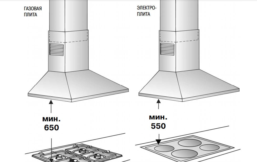
The hood must be located strictly above the stove. Follow the requirements of the distance from the stove to the hood, depending on the type of stove and hood. When marking, consider the height of the hood itself.
Installation can begin with drilling the wall according to the markings.
If it is important to keep cleanliness right during drilling, you will need an assistant who can collect dust directly from the hammer with a vacuum cleaner. If the house is wooden:
If the house is wooden:
- In the center of the hole marking, we drill a hole with an ordinary thin drill bit for wood.
- Outside, draw a circle of the desired diameter around the hole.
- Cut out a hole with a jigsaw.
- We clean the resulting hole from construction debris, align the edges.
- We install inside the pipe and check valves.
- Outside, we install a grill.
The following steps are aimed at installing the hood and connecting pipes to it. These tasks can be done in any convenient order.
Fixing the hood itself is carried out strictly according to the instructions for it.
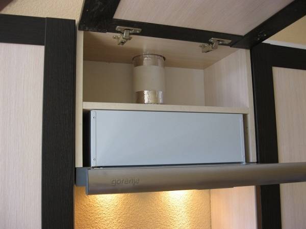
Typically, the hood is attached in one of two ways - to the wall or by mounting in a wall cabinet.
If the installation is carried out inside the furniture, then the connection is organized inside the cabinet, and the electricity for it is supplied to a common terminal, from where the lighting above the table is connected, and, if necessary, a socket. Thus wiring, switches and sockets are hidden. If wiring for other tasks is not provided, an autonomous installation of the socket is implemented.
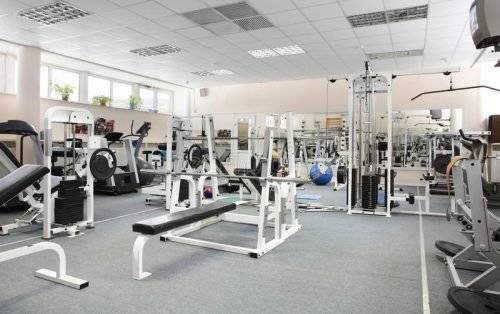
Ventilation Requirements
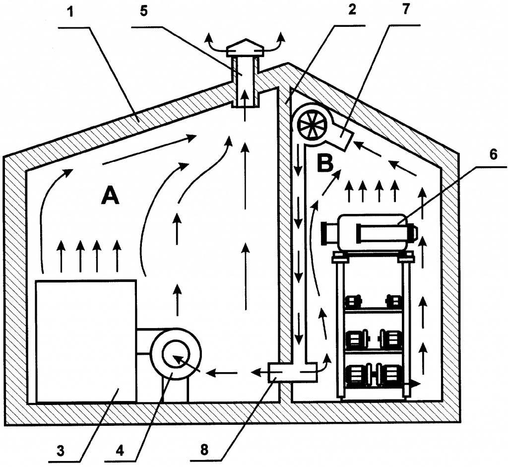
For sports halls, built-in ventilation cannot cope with a heavy load. The built-in system only partially purifies the air. Improper airflow can harm not only athletes or gym customers, but also workers who are in the room every day.
There are always a lot of people in the gym. Some are engaged in professional sports, while others are simply looking for additional ways to improve their own body. In places where many people pass, the air is always polluted.A musty, poorly ventilated room gathers a lot of germs and bacteria that can infect anyone.
An unpleasant odor is one of the first reasons why additional ventilation or an exhaust hood is installed. In a fitness room or for a sports school, thermal sensors can be integrated into the system. Such measures will help not only to clean the air in the room in a timely manner, but also to maintain the desired temperature regime.


The ventilation requirements are the simplest:
- the system must maintain the optimum temperature throughout the room;
- air exchange and fresh air supply must be constant and uninterrupted;
- drafts and strong air currents are excluded.
They equip ventilation with valves that do not allow the air flow to return back to the room. The gym can be equipped with valves at the windows or along natural ventilation.
Sports clubs cannot be equipped only with air conditioners or hoods, without ensuring a full and correct air exchange in the hall. By the multiplicity of air intake, which returns to the sports room, the productivity of the system is determined.
The construction of the centers is carried out according to the norm determined by the legislation. These standards correspond to the air and the level of humidity in the centers. The gym is a special place where the humidity constantly rises and unpleasant odors are present.
Without the uninterrupted operation of individual parts of the system, it will not be possible to ensure proper air exchange in the building. Cleaned and filtered air is returned to the place of the taken air through the devices built into the ventilation.
In gyms, an unpleasant smell is a sign that the ventilation system is not working properly.In such gyms, it will not be possible to do fitness without harm to health. Too much cold fresh air for the gym is also not the best indicator.
The main sign of improper operation of the ventilation system in the gym is an unpleasant smell.
Required machine power
The power of the device is an important parameter. If it is calculated correctly, there will be no problems with the microclimate in the room. The power is calculated according to the formula: Q=S*H*12, where Q is the performance of the device (power), measured in m3/h, S is the area of the room, H is the height of the room, 12 is the coefficient (according to standards, the air in the kitchen should change 12 times in an hour).
Calculation example:
- the area of the room is 12 m2;
- room height - 2.7 m.
So: Q=12*2.7*12=388.8 m3/h. Based on the calculation, the performance of the unit should be at least 388.8 m3 / h. But it is recommended to buy a unit with a power reserve of approximately 30% more.
Acceptable concentration method
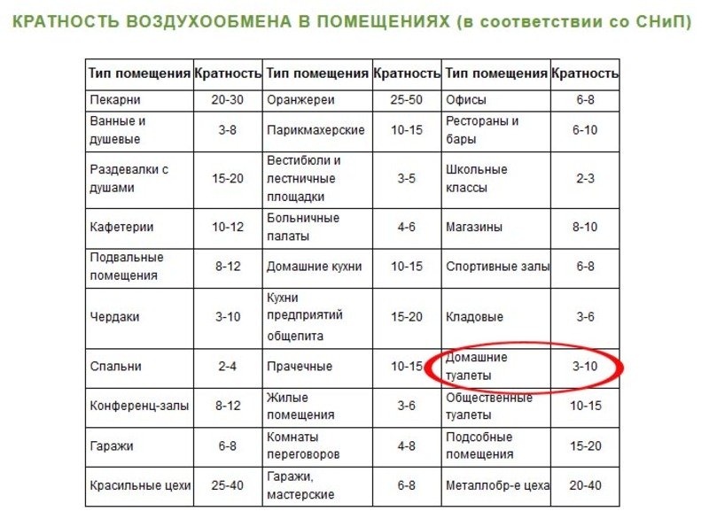
To apply this method in a simplified version, complex air pollution with harmful substances is indirectly estimated only by the content of carbon dioxide CO2exhaled by a person. Air exchange must ensure the concentration of CO2 indoors, depending on the requirements of the table, see the article “Standards for the concentration of carbon dioxide (CO2) in living quarters. In ventilation systems, flow control according to the readings of the CO concentration sensor2 rarely used it is known that providing air quality according to the criterion of consumption m3 / (hour x person) approximately leads to ensuring the same air quality according to the criterion of CO concentration2. Within the framework of this article, the method of permissible concentrations is not considered in detail.
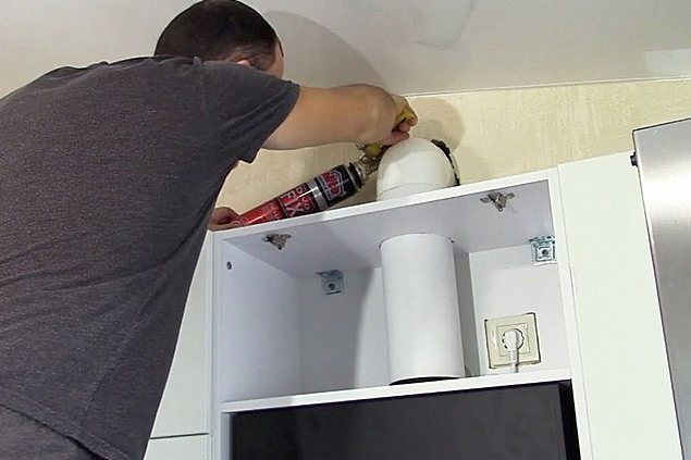
Embedded
Installation of the hood in the kitchen begins with choosing the right location for its location relative to the ventilation shaft. If you want to install a built-in hood, then for this you will have to redo it a little (shorten the cabinet). It is better to contact the furniture makers on this issue so that they carefully (on a format-cut machine) cut the side walls and drill two large holes for the corrugation with a “crown”. Or you can order from them a ready-made cabinet, made to the size of the unit, which will take into account the installation height of the hood. They will also fix the device inside the cabinet, closing it with a facade. At home, you can’t make a cupboard under the hood in the kitchen with your own hands. When the cabinet is ready, you only need to hang it on the wall.
Types of residential buildings
Considering residential buildings, you can divide them into typical and individual.
Typical ones are template samples that demonstrate ready-made solutions, where key points are developed. They are used in large-scale buildings. In such blanks, minor adjustments are made to local conditions. For example, orientation on the ground or a place to connect to networks.
And a special house, with unique layouts and facades, with personal wishes and ideas, is called individual.
It is also divided into multi-family and single-family houses.
Multi-apartment houses are called houses that have joint premises and engineering outside the apartment boundaries.
This also includes boarding schools, hostels and hotel complexes.
Often in skyscrapers there are other non-residential facilities: parking lots, retail outlets, service organizations and others.
Is it necessary to ventilate a boiler room in a private house, and why?
Yes, in the boiler rooms of private houses it is imperative to organize ventilation that meets the standards of SNiP.
In this room, the ventilation system will perform the following functions:
- Provide oxygen supply for normal combustion. If there is not enough oxygen, any fuel will not burn completely. As a result, less heat is released, more fuel is spent to maintain the desired temperature in residential premises, the wear of the boiler is accelerated, and ashes accumulate inside the chimney.
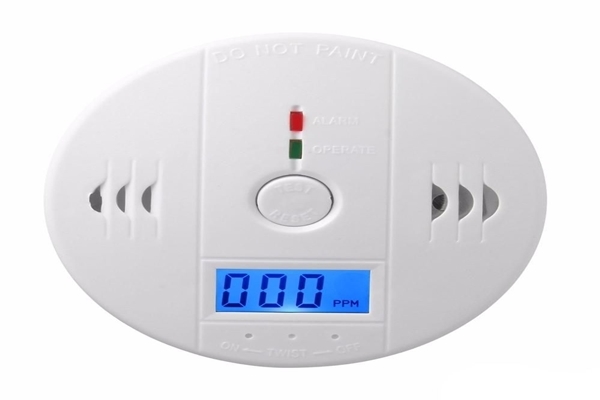
- Remove carbon monoxide. Not all combustion products can be removed through the chimney - in a small amount they can enter the room. If ventilation does not provide sufficient air exchange, the concentration of carbon monoxide can rise to critical levels and penetrate into other rooms.
- Remove gas if possible. Over time, the gas line to the boiler may lose its tightness, and gas may accumulate in the room. If this is not noticed, an explosion or poisoning is possible.
That is, properly equipped furnace ventilation gives the following effect:
- reduces the risk of fire or explosion;
- reduces the likelihood of natural or carbon monoxide poisoning;
- the boiler works with full efficiency, without exceeding loads (which means it can last longer without repair);
- the temperature in the house is maintained without excessive load on the boiler and without exceeding the fuel consumption.
The main rules and requirements for ventilation of the boiler room in accordance with SNiP (+ video)
Do you need a ventilation system - found out. Now about the main rules and requirements for its arrangement.
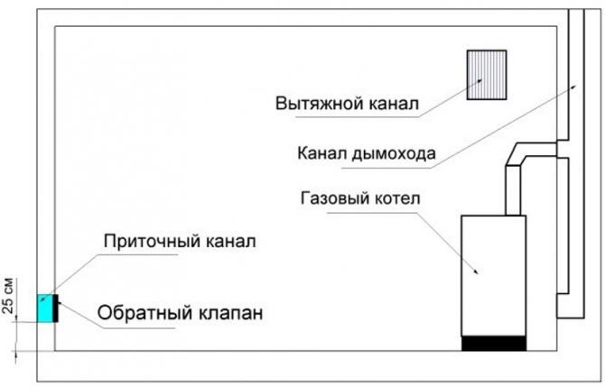
Simplified boiler room ventilation scheme
The boiler room can be equipped in such premises:
- Freestanding building or block module.
- Annex.
- Room inside the house.
- Kitchen (permissible if the boiler power does not exceed 30 kW).
- Attic.
During the construction of private houses, furnaces are usually equipped in a separate room on the ground floor, next to a garage or other room.
Requirements and standards for the arrangement of boiler rooms in private homes are regulated in SNiP 42-02-2002.
From the main requirements:
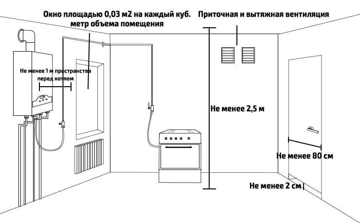
- Requirements for the room, if the boiler is placed in a separate room: volume - from 7.5 m³, area - from 6 m², ceiling height - from 2.5 m.
- Boilers with a capacity of 30+ kW - should be installed only in a separate room. Boilers with less power - can be placed in the kitchen.
- When installing the boiler in the kitchen, its area must be more than 15 m²
- The boiler room must have a separate door to the street.
- The cross-sectional area of the openings for inflow: from the street - from 8 cm² for every 1 kW of boiler power, from an adjacent room (for example - from the kitchen, through the wall) - from 30 cm² for every 1 kW of power.
Air exchange calculation with formula and example (+ video with more detailed explanations)
It is necessary to choose the sections of the ventilation ducts and the power of the exhaust fan based on the desired air exchange.
To calculate the right amount of air, you need to know:
The rate of air exchange. According to SNiP - for boiler rooms it is 3 (that is, in 1 hour in the boiler room, the air must be completely updated 3 times).
The volume of the room. To measure, you need to multiply the height by the width and multiply by the length (all values \u200b\u200bare taken in meters).
How much air does the boiler need for combustion


For gas boilers (it doesn’t matter - with an open or closed combustion chamber) in private homes, high accuracy is not necessary, so you can take 10 “cubes” of air per 1 “cube” of gas for calculations. For diesel fuel - 12.
Let's give an example - let's calculate the ventilation system for a boiler room in a separate room attached to the house:
- We calculate the volume of the room. For example, let's take the dimensions 2.5 x 3.5 x 2.5 = 21.875 m³. For a more accurate calculation, you can subtract the volume (size) of the boiler itself from the “total” volume.
- We look in the characteristics of our boiler how much gas it can burn maximum in 1 hour. For example, we have a model Viessmann Vitodens 100 (35 kW), with a maximum consumption of 3.5 "cubes". This means that for normal combustion at maximum load, the boiler needs 3.5 x 10 = 35 m³ / h of air. This characteristic is not covered by the rule about three times, so we simply add it to the result.
Now we perform the calculation using all indicators:
21.875 x 3 (three air changes) + 35 = 100 m³/h
Just in case, you need to make a reserve - on average up to + 20-30% of the resulting value:
100 + 30% = 130 m³/h (rounded up) must be supplied and removed by the ventilation system in the boiler room at maximum load on the boiler. For example, we took the maximum margin (30%), in fact, you can limit yourself to 15-20%.
7.2 Calculation of the air flow rate removed by local exhausts and ventilated ceilings
Calculation of the dimensions of local suction
and air flow rate removed by local exhausts and ventilated ceilings,
allowed to be carried out by manufacturers - suppliers of equipment. Wherein
the latter are responsible for the correctness of the calculations and for the fact that local
suction and ventilated ceilings installed and operated in accordance with their
calculations and recommendations will fully capture kitchen secretions.
7.2.1 Calculation of convective flow over hot
surface of kitchen equipment
Air flow rate removed by local
suction, determined from the calculation of capturing the convective flow, ascending
over the hot surface of kitchen equipment.
Air flow in convective
flow over individual kitchen equipment Lki, m3/s,
calculated according to the formula
Ltoi = kQto1/3(z + 1,7D)5/3r, (1)
where k—
experimental coefficient equal to 5·10-3m4/3·Wt1/3·s-1;
Qto — share of convective heat releases from kitchen equipment, W;
z - distance from the surface of kitchen equipment
to local suction, m (Figure 4);
D - hydraulic diameter of the surface of the kitchen
equipment, m;
ris the correction for the position of the heat source according to
in relation to the wall accept according to the table 1.
Figure 4 - Convective flow over the surface of kitchen equipment:
Ltoi- convective air flow over the individual
kitchen equipment, m3/s; z- distance from the surface of kitchen equipment
to local suction, m; h- height
kitchen equipment, usually equal to 0.85 to 0.9 m; Qto - convective heat dissipation of the kitchen
equipment, W; BUT, AT respectively length and width
kitchen equipment, m
Table
1 - Correction for the position of the heat source in relation to the wall
| Position | Coefficient r | |
| Free | 1 | |
| Near the wall | 0,63ATBUT, but not less than 0.63 and not more than 1 | |
| In the corner | 0,4 |
The share of convective
heat dissipation of kitchen equipment Qto, W, determined by the formula
Qto = QtToITotoToabout, (2)
where Qt - installed capacity of kitchen equipment,
kW;
ToI — the share of sensible heat generation from the installed capacity of the kitchen
equipment, W / kW, are accepted according to;
Toto is the share of convective heat release from sensible heat release from the kitchen
equipment. In the absence of data for a specific equipment, it is allowed
accept Toto = 0,5;
Toabout - the coefficient of simultaneity of the kitchen equipment, take
on .
Hydraulic diameter of the kitchen surface
equipment D, m, is determined by the formula
(3)
where BUT - the length of the kitchen
equipment, m;
AT - width of kitchen equipment, m.
7.2.2 Calculation of the air flow,
removed by local suction

Exhaust air flow
local suction, Lo, m3/s, determined by the formula
(4)
where n- amount
equipment located under suction;
Lki - the same as in formula (1);
Lri - volumetric consumption of products
combustion of kitchen equipment, m3/s. For equipment running
on electricity, Lri = 0. For gas powered equipment,
calculated according to the formula
Lri = 3,75·10-7QtToabout, (5)
where Qt, Ko
— the same as in formula (2);
a - correction factor,
taking into account air mobility in hot shop, take according to the table
2 depending on the air distribution system;
Toto is the coefficient of efficiency of local suction. For standard local
suctions are taken equal to 0.8. Activated local suctions (with blowing
supply air) have an efficiency factor higher than 0.8. For such
sucks value Toto accepted according to the manufacturer.
Manufacturers of activated local suctions with Toto > 0,8
must submit test results for the activated
suction to confirm the declared efficiency ratio.
Approximately, in the absence of data, you can take Toto =
0,85.
table 2
| Way | Coefficient a |
| Stirring | |
| Inkjet | |
| through | 1,25 |
| through | 1,20 |
| displacement ventilation | |
| Innings | |
| on the ceiling | 1,10 |
| in working | 1,05 |
| * Air speed referred to total |
7.2.3 Flow calculation
air removed by ventilated ceiling
Exhaust air flow
ventilated ceiling, Lo, m3/s, calculated from
formula
(6)
where Lki - then
the same as in the formula (); when calculating Lki
height z taken equal to the distance from the surface of the kitchen
equipment to the ceiling, but not less than 1.5 m;
Lri, and - the same as in the formula ().
What to consider at the design stage?
At the stage of development of the project of the ventilation system, the following points are subject to agreement:
- Features of the architecture and design of the office building/offices.
- Location of equipment.
- The probable location of the channels through which the air flow will flow.
- An indicator of the power of an electrical installation.
- Availability of the possibility of supplying water, as well as possible ways to drain condensate. Providing free access to the ventilation system.
- Possibility (if necessary) to make changes to the design.
In the design of the ventilation system, it is not worth making adjustments for the operation of the air conditioning system as another source of air exchange.
This is explained very simply - only the ventilation system provides adequate air exchange.
The successful combination of an air conditioner with forced ventilation allows you to supply fresh, humidified and purified air into the room, while saving on electricity
Air conditioners are designed to improve the characteristics of the incoming air (temperature correction, humidification, purification from harmful components), but not even the most modern air conditioner will provide fresh, O2-enriched air.
Another issue is central air conditioners with fresh air supply, which can provide an air supply that meets all requirements.
The process of designing a ventilation network includes the following calculations:
- Air flow exchange.
- Communication schemes.
- Heat inflows. The calculation is carried out for each room separately, adjusted for the technical and design features of the building.
- The cross-sectional areas of the paths along which the exchange of air flows occurs.
- Pressure losses in the network of ventilation ducts.
- The required power of the heater.
In addition, the equipment necessary for the assembly and assembly of the ventilation network is determined. Documentation for the project is drawn up and all details are agreed upon.


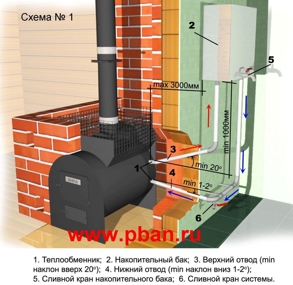
Ventilation for the boiler: its parameters and scheme
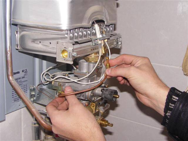
A gas boiler with an insulated combustion chamber is equipped with a coaxial duct. Such a chimney allows you to simultaneously remove smoke and deliver fresh oxygen.
The design consists of two pipes of different diameters, the smaller of which is located inside the large one. Smoke is removed through the inner pipe of a smaller diameter, and fresh oxygen enters through the space between the pipes.
Standards for installing a gas boiler and arranging ventilation:
- One or two gas appliances can be connected to the chimney, no more. This rule applies regardless of distance and location.
- The ventilation duct must be airtight.
- Seams are treated with sealants, the properties of which make it possible to provide insulation under the influence of high temperatures.
- The system must be made of non-combustible materials.
- Horizontal sections of the hood should consist of two channels: one for removing smoke, the second for cleaning.
- The channel intended for cleaning is located below the main one by 25-35 cm.
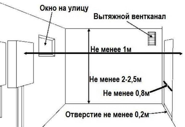
There are strict requirements for ventilation in terms of dimensions and distances:
- The space from the horizontal pipe to the ceiling is at least 20 cm.
- The walls, floor and ceiling of the room must be made of non-combustible materials.
- At the outlet of the pipe, all combustible materials must be sheathed with a layer of non-combustible insulation.
- The distance from the outer wall, from where the pipe exits, to the end of the chimney should not be less than 30 cm.
- If there is another wall opposite the horizontal pipe, the distance to it should not be less than 60 cm.
- The distance from the ground to the pipe is at least 20 cm.
Ventilation requirements for an open combustion boiler:
- Equipped with a channel for removing smoke.
- A common system is being set up with an efficient supply of the required volumes of oxygen.
Exhaust and supply ventilation for a gas boiler is located in opposite corners, equipped with a check valve.It will provide protection in the event of a violation of the direction of movement of flows, when combustion products will be drawn into the building, and fresh air will go outside.
Dimensional parameters of ventilation are calculated based on the required volumes of gas removal and oxygen supply. The output volumes are equal to three units of the air exchange rate in the room. The air exchange rate is the amount of air passing through the room per unit of time (one hour). The oxygen supply is equal to three units of multiplicity plus the volume absorbed by combustion.
The diameter of the air duct is calculated based on the power of the boiler
An example of calculating the parameters of air exchange:
- Room dimensions: length (i) 3 meters, width (b) 4 meters, height (h) 3 meters. The volume (v) of the room is 36 cubic meters and is calculated by the formula (v = I * b * h).
- The air exchange rate (k) is calculated by the formula k \u003d (6-h) * 0.25 + 3. We consider - k \u003d (6-3) * 0.25 + 3 \u003d 3.75.
- The volume that passes in an hour (V). V = v * k = 36 * 3.75 = 135 cubic meters.
- Cross-sectional area of the hood (S). S = V/(v x t), where t (time) = 1 hour. S \u003d 135 / (3600 x 1) \u003d 0.037 sq. m. The inlet should be of the same size.
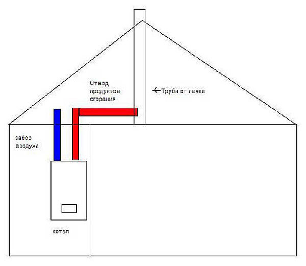
The chimney can be equipped in various ways:
- Exit horizontally to the wall.
- Exit to the wall with a bend and rise.
- Vertical exit to the ceiling with a bend.
- Direct vertical exit through the roof.
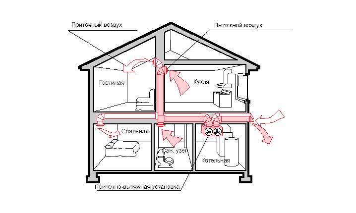
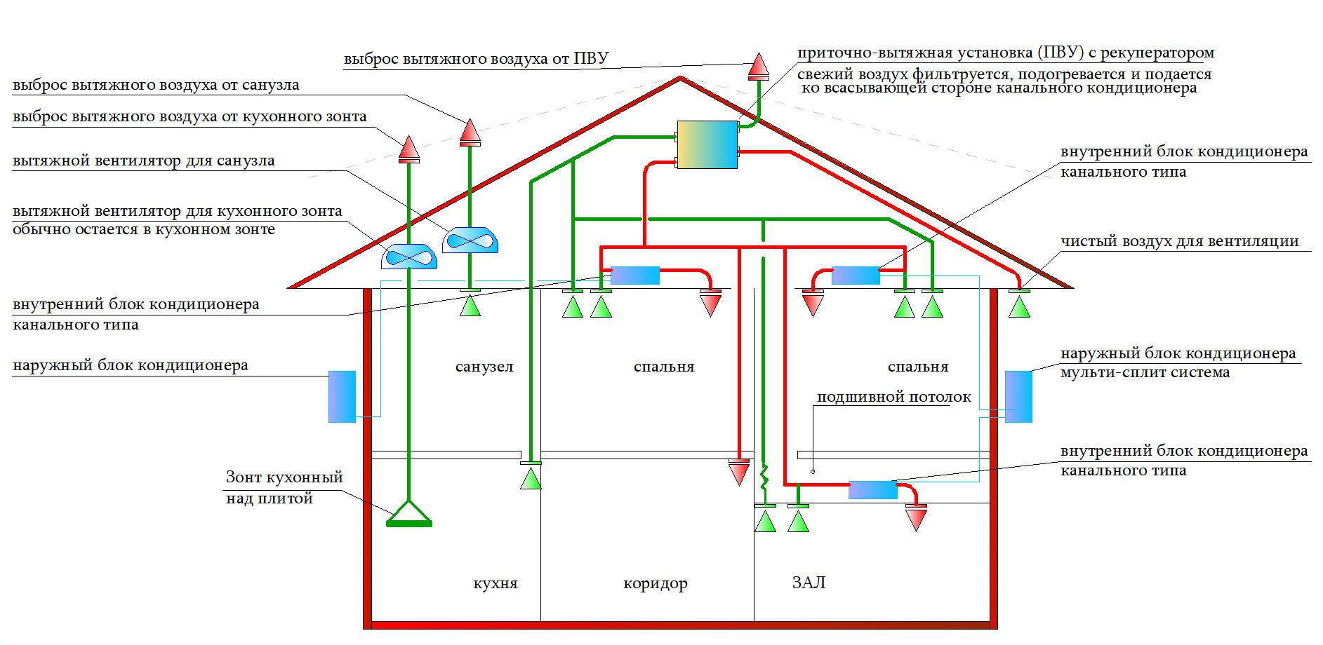
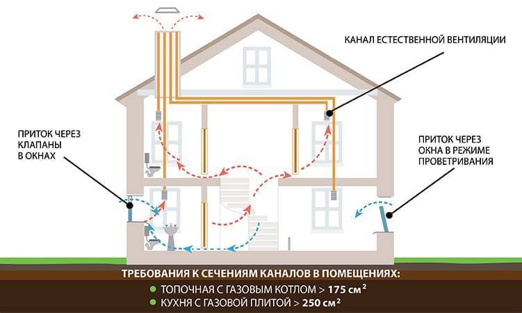
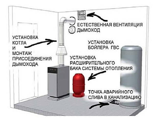
The ventilation scheme in a private house with a coaxial chimney is as follows:
- gas boiler;
- angular coaxial outlet;
- coaxial pipe;
- condensate drain;
- filter;
- protective grille;
- horizontal and vertical tips;
- roof lining.
Law
Under current housing legislation, tariffs as of January 1, 2020 cannot exceed tariffs as of December 31, 2019. This is due to the Decree of the President of the Russian Federation that tariffs for housing and communal services should not increase faster than last year's inflation. 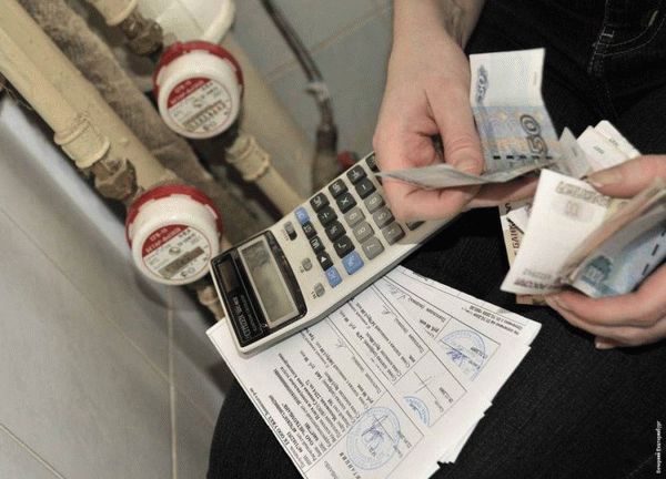 The law on raising housing and communal services tariffs for 2020 was adopted in 2019, therefore, inflation in 2019 is taken into account. According to Rosstat, in 2019 it was 4%.
But, within the framework of the law, local regional authorities can increase or decrease the rate.
Another innovation that awaits us is the draft law on the “single receipt”, which provides for amendments to Art. 155 of the Housing Code. It is currently under consideration in the State Duma.
The bill on the EPD (Single Payment Document), which will contain detailed information on all housing and communal services - what, to whom, and how much a citizen should pay. These receipts will be sent electronically.
Also, on August 6, 2019, the Government of the Russian Federation developed a transition to a new method for setting tariffs for heat supply, water supply and sanitation. The purpose of such a plan is to increase the fairness and transparency of tariff setting.
It is planned to make tariffs loyal for citizens and sufficient for resource-supplying organizations, based on market prices and technologies used.