- 5 Rules for warming
- Parameter table
- Roof aerators
- Operating principle
- Passage of a chimney pipe through a tiled roof
- 4 Node device
- Installation of ventilation passage nodes through the roof
- Conclusion - briefly about the main
- Features of installation of a typical design
- The subtleties of installing a ventilation network
- How to bypass the pipe?
- General characteristics of roof ventilation units
- Description and purpose of passage nodes
5 Rules for warming
Internal thermal insulation not only prevents condensation, but also significantly improves the aerodynamic characteristics of the system as a whole, making its operation more efficient. In addition, the structure can be insulated from the outside - this is necessary to increase the operating parameters of the ventilation duct. External thermal insulation of the system has a number of advantages:
- 1. Reduces heat transfer, which has a positive effect on the level of thrust.
- 2. Reduces the noise and vibrations that accompany the operation of the system.
- 3. Minimizes the risk of mold and frost due to excessive moisture.
- 4. The risk of fire is minimized.
It is necessary to choose thermal insulation materials, taking into account certain factors. Some of them:
- 1. Dimensions of the ventilation shaft on the roof, its structure.
- 2. Indicators of heat conductivity of the materials used.
- 3. Presence of a dew point.
- four.Temperature differences between the internal base and the structure of the ventilation complex.
It should be noted that condensation does not form on brick systems, so it is not necessary to carry out thermal insulation. For external insulation, slabs for the facade based on gypsum slag are often used, and so on.
The process consists of several stages:
- 1. First, surface preparation is carried out - cleaning, dismantling of weak areas. Then it is treated with a primer.
- 2. A special adhesive mixture is used to fix the boards. With its help, edging and installation of a blotch is performed.
- 3. Then install the facade dowels. This is done after the adhesive mixture has completely cured.
- 4. Installation of a reinforcing base made of adhesive and fiberglass materials.
- 5. After the glue has dried, the surfaces are treated with a primer. Then plastering is carried out.
Parameter table
vendor code
d1, mm
d2, mm
B, mm
A, mm
H, mm
Weight, kg
K2.MU.UPK45.080
80
90
380
520
200
2
K2.MU.UPK45.100
100
110
400
530
200
2,10
K2.MU.UPK45.110
110
120
410
540
200
2,20
K2.MU.UPK45.115
115
125
415
540
200
2,20
K2.MU.UPK45.120
120
130
420
560
200
2,30
K2.MU.UPK45.130
130
140
430
570
200
2,35
K2.MU.UPK45.140
140
150
440
580
200
2,40
K2.MU.UPK45.150
150
160
450
590
200
2,50
K2.MU.UPK45.160
160
170
460
610
200
2,50
K2.MU.UPK45.180
180
190
480
640
200
2,70
K2.MU.UPK45.200
200
210
500
660
200
2,90
K2.MU.UPK45.210
210
220
510
680
200
2,90
K2.MU.UPK45.220
220
230
520
690
200
2,90
K2.MU.UPK45.230
230
240
530
700
200
3
K2.MU.UPK45.240
240
250
540
710
200
3,10
K2.MU.UPK45.250
250
260
550
730
200
3,10
K2.MU.UPK45.260
260
270
560
750
200
3,50
K2.MU.UPK45.280
280
290
580
870
200
4,10
K2.MU.UPK45.300
300
310
600
800
200
4,50
K2.MU.UPK45.320
320
330
620
850
200
4,90
K2.MU.UPK45.350
350
360
650
870
200
5,40
K2.MU.UPK45.400
400
41
700
940
200
5,80
K2.MU.UPK45.450
450
460
750
1010
200
6,30
K2.MU.UPK45.500
500
510
800
1080
200
6,70
K2.MU.UPK45.550
550
560
850
1150
200
7,30
K2.MU.UPK45.600
600
610
900
1220
200
7,80
K2.MU.UPK45.650
650
660
950
1290
200
7,80
K2.MU.UPK45.700
700
710
1000
1360
200
7,90
K2.MU.UPK45.750
750
760
1050
1420
200
8,10
K2.MU.UPK45.800
800
810
1100
1490
200
8,10
K2.MU.UPK45.850
850
860
1150
1630
200
8,70
K2.MU.UPK45.900
900
910
1200
1640
200
9,70
K2.MU.UPK45.1000
1000
1010
1300
1770
200
10,70
K2.MU.UPK45.1100
1100
1110
1400
1980
200
11,20
vendor code
K2.MU.UPK45.080
- K2.MU.UPK45.080
- K2.MU.UPK45.100
- K2.MU.UPK45.110
- K2.MU.UPK45.115
- K2.MU.UPK45.120
- K2.MU.UPK45.130
- K2.MU.UPK45.140
- K2.MU.UPK45.150
- K2.MU.UPK45.160
- K2.MU.UPK45.180
- K2.MU.UPK45.200
- K2.MU.UPK45.210
- K2.MU.UPK45.220
- K2.MU.UPK45.230
- K2.MU.UPK45.240
- K2.MU.UPK45.250
- K2.MU.UPK45.260
- K2.MU.UPK45.280
- K2.MU.UPK45.300
- K2.MU.UPK45.320
- K2.MU.UPK45.350
- K2.MU.UPK45.400
- K2.MU.UPK45.450
- K2.MU.UPK45.500
- K2.MU.UPK45.550
- K2.MU.UPK45.600
- K2.MU.UPK45.650
- K2.MU.UPK45.700
- K2.MU.UPK45.750
- K2.MU.UPK45.800
- K2.MU.UPK45.850
- K2.MU.UPK45.900
- K2.MU.UPK45.1000
- K2.MU.UPK45.1100
- d1, mm
80 - d2, mm
90 - B, mm
380 - A, mm
520 - H, mm
200 - Weight, kg
2
- d1, mm
100 - d2, mm
110 - B, mm
400 - A, mm
530 - H, mm
200 - Weight, kg
2,10
- d1, mm
110 - d2, mm
120 - B, mm
410 - A, mm
540 - H, mm
200 - Weight, kg
2,20
- d1, mm
115 - d2, mm
125 - B, mm
415 - A, mm
540 - H, mm
200 - Weight, kg
2,20
- d1, mm
120 - d2, mm
130 - B, mm
420 - A, mm
560 - H, mm
200 - Weight, kg
2,30
- d1, mm
130 - d2, mm
140 - B, mm
430 - A, mm
570 - H, mm
200 - Weight, kg
2,35
- d1, mm
140 - d2, mm
150 - B, mm
440 - A, mm
580 - H, mm
200 - Weight, kg
2,40
- d1, mm
150 - d2, mm
160 - B, mm
450 - A, mm
590 - H, mm
200 - Weight, kg
2,50
- d1, mm
160 - d2, mm
170 - B, mm
460 - A, mm
610 - H, mm
200 - Weight, kg
2,50
- d1, mm
180 - d2, mm
190 - B, mm
480 - A, mm
640 - H, mm
200 - Weight, kg
2,70
- d1, mm
200 - d2, mm
210 - B, mm
500 - A, mm
660 - H, mm
200 - Weight, kg
2,90
- d1, mm
210 - d2, mm
220 - B, mm
510 - A, mm
680 - H, mm
200 - Weight, kg
2,90
- d1, mm
220 - d2, mm
230 - B, mm
520 - A, mm
690 - H, mm
200 - Weight, kg
2,90
- d1, mm
230 - d2, mm
240 - B, mm
530 - A, mm
700 - H, mm
200 - Weight, kg
3
- d1, mm
240 - d2, mm
250 - B, mm
540 - A, mm
710 - H, mm
200 - Weight, kg
3,10
- d1, mm
250 - d2, mm
260 - B, mm
550 - A, mm
730 - H, mm
200 - Weight, kg
3,10
- d1, mm
260 - d2, mm
270 - B, mm
560 - A, mm
750 - H, mm
200 - Weight, kg
3,50
- d1, mm
280 - d2, mm
290 - B, mm
580 - A, mm
870 - H, mm
200 - Weight, kg
4,10
- d1, mm
300 - d2, mm
310 - B, mm
600 - A, mm
800 - H, mm
200 - Weight, kg
4,50
- d1, mm
320 - d2, mm
330 - B, mm
620 - A, mm
850 - H, mm
200 - Weight, kg
4,90
- d1, mm
350 - d2, mm
360 - B, mm
650 - A, mm
870 - H, mm
200 - Weight, kg
5,40
- d1, mm
400 - d2, mm
41 - B, mm
700 - A, mm
940 - H, mm
200 - Weight, kg
5,80
- d1, mm
450 - d2, mm
460 - B, mm
750 - A, mm
1010 - H, mm
200 - Weight, kg
6,30
- d1, mm
500 - d2, mm
510 - B, mm
800 - A, mm
1080 - H, mm
200 - Weight, kg
6,70
- d1, mm
550 - d2, mm
560 - B, mm
850 - A, mm
1150 - H, mm
200 - Weight, kg
7,30
- d1, mm
600 - d2, mm
610 - B, mm
900 - A, mm
1220 - H, mm
200 - Weight, kg
7,80
- d1, mm
650 - d2, mm
660 - B, mm
950 - A, mm
1290 - H, mm
200 - Weight, kg
7,80
- d1, mm
700 - d2, mm
710 - B, mm
1000 - A, mm
1360 - H, mm
200 - Weight, kg
7,90
- d1, mm
750 - d2, mm
760 - B, mm
1050 - A, mm
1420 - H, mm
200 - Weight, kg
8,10
- d1, mm
800 - d2, mm
810 - B, mm
1100 - A, mm
1490 - H, mm
200 - Weight, kg
8,10
- d1, mm
850 - d2, mm
860 - B, mm
1150 - A, mm
1630 - H, mm
200 - Weight, kg
8,70
- d1, mm
900 - d2, mm
910 - B, mm
1200 - A, mm
1640 - H, mm
200 - Weight, kg
9,70
- d1, mm
1000 - d2, mm
1010 - B, mm
1300 - A, mm
1770 - H, mm
200 - Weight, kg
10,70
- d1, mm
1100 - d2, mm
1110 - B, mm
1400 - A, mm
1980 - H, mm
200 - Weight, kg
11,20
Roof aerators
To prevent the formation of condensation, which promotes the development and spread of fungus and mold, the roof system must be well ventilated. For these purposes, special elements are additionally installed on the roof, which are called aerators.
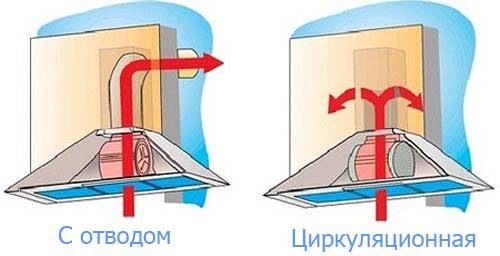
Operating principle
- Air will enter special technical openings installed in the roof eaves.
- Then, naturally passing through the entire roof from the bottom up, it will exit through the aerators located closer to the ridge.
It is this simple system of natural ventilation that will guarantee the absence of condensation under the roof.
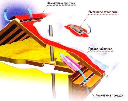
Principle of roof ventilation
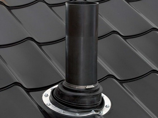
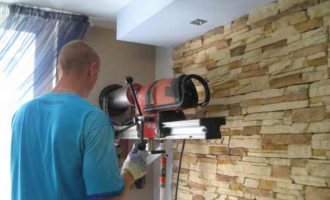
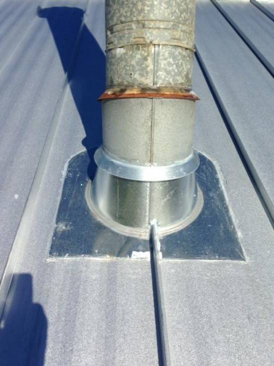
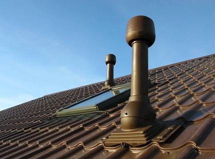
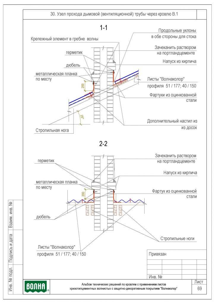
Passage of a chimney pipe through a tiled roof
Separately, I would like to say about the passage of the pipe through the tiled roof. Manufacturers have thought of a special element that repeats the relief pattern of the tiles, and has a hole arranged for the pipe. A pipe of the same material is also selected for it.
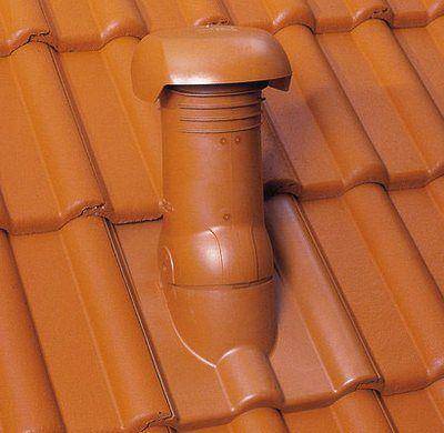
These elements of a tiled roof are made of highly resistant plastic.They are produced in the same colors as the tiles, and you can always choose the right shade suitable for a particular building. But such plastic roof parts are installed only for ventilation ducts, since they are unlikely to withstand the high temperatures that accompany the smoke emanating from any stove.
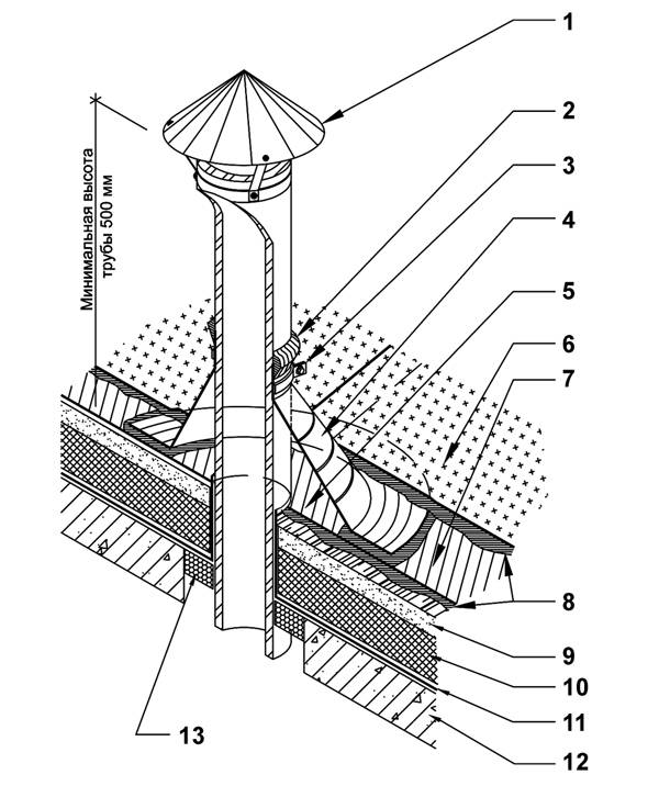
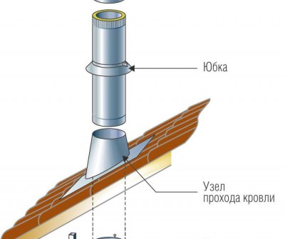
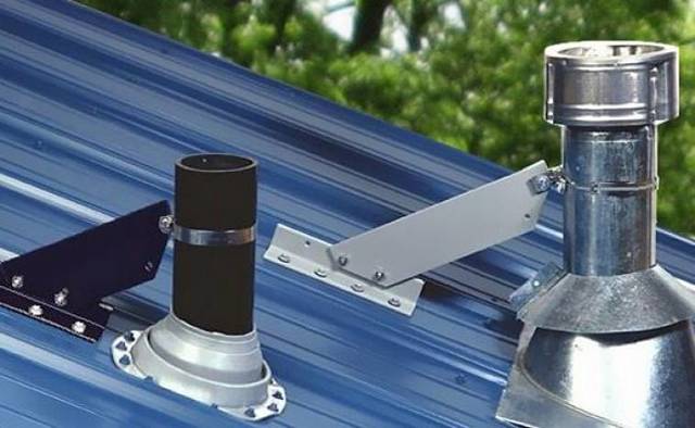
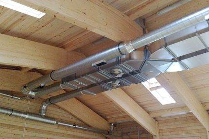
4 Node device
At the bottom of the pipe, with the help of a flange, an outlet channel is attached, and on top there is a deflector or a conventional protective umbrella. You can also consider the option with a heater, in the role of which mineral wool is used.


The modern market offers more advanced types of roof ventilation systems that correspond to a new level of quality. At the same time, in terms of design features and principle of operation, they practically do not differ from traditional solutions, but they have a lot of advantages.
Covers from the manufacturer "Vlipe Vent" are in special demand. The list of advantages of such products includes the following items:
- 1. High quality workmanship. Pipe models available on the market are made from high quality materials. If the inner pipe is made of the best galvanized steel, then the outer one is made of reliable lightweight polypropylene.
- 2. Reliable fastening. To fix the element, a special pass-through element of the corresponding shape is used.
- 3. The height of the pipe is between 400mm and 700mm.
- 4. A seal is located at the bottom of the pipe, which allows it to be inserted into the air duct to a depth of up to 300 millimeters.
- 5. The inner diameter of the pipes is 110-250 mm.
- 6. The ventilation outlet pipe is equipped with a special heat insulator, which prevents the possible formation of an ice plug in the cold season.In addition, good thermal insulation prevents condensation.
- 7. An electric fan can be installed on the ventilation outlets, which will create forced ventilation.
- 8. A hood with a deflector is the best protection against rain. In addition, it enhances traction.
In some circumstances, where a feed-through is not included and is purchased as an optional unit, the type and profile of the roofing must be carefully assessed to determine the optimum unit. A high-quality pass-through element will be the best solution for ensuring the versatility of the structure on any type of roof. Such products guarantee maximum stability and tightness of the ventilation outlet.
Installation of ventilation passage nodes through the roof
A properly installed roof duct assembly must meet the following requirements:
Tightness. The connecting flange must be carefully sealed to exclude the possibility of water leakage into the attic.
No obstruction to the runoff of rain or melt moisture
This is especially important in the spring-autumn period, when the water remaining in the cracks of the surface freezes at night and expands them, violating the tightness of the passage and the integrity of the coating.
The thermal insulation of the passage assembly eliminates the appearance of condensate that destroys the rafters, roofing and other elements of the system.
The upper part of the duct is protected by a deflector that prevents rainwater or birds from entering. This applies to all types of air ducts, except for sewer pipes.

The upper part of the duct is protected by a deflector
Most passage nodes have similar shapes, but there are also original options.

Some types of UE have a ready-made deflector made in the form of a wide protective cap
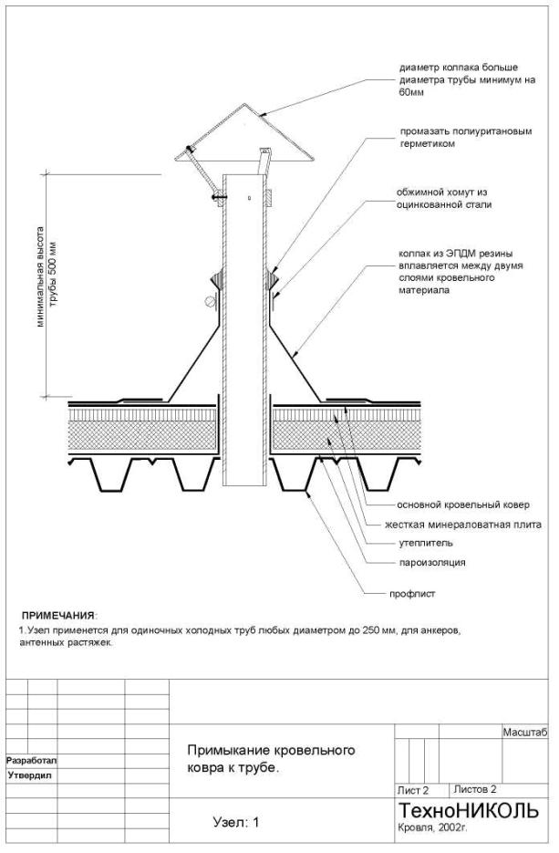
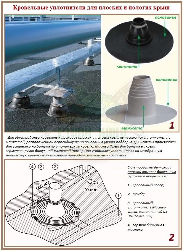
The installation technology of the UE depends on its type, type of roofing, roof slope and other factors. One of the easiest options is to install an elastic penetration.

The procedure can be seen in the picture.
All actions consist in making a hole of the appropriate diameter so that the air duct tightly wraps around it and does not let moisture in. Then the edges are pressed with a mounting washer, which is crimped according to the shape of the relief of the roofing.

The penetration material itself serves as a seal, which is convenient and eliminates the need for additional elements.
The general installation procedure consists of the same steps:
- Roof marking. The diameter (size) of the hole must be made 2-3 cm larger than the size of the duct. The easiest way is to take a small piece of pipe or make a template that exactly repeats its shape. It is applied to the surface of the coating and outlined with a small margin.
- The hole is cut out in a manner appropriate to the type of roofing material. For example, if you need to install a ventilation passage unit through a corrugated roof, you cannot use a grinder. Using an electric drill, a series of holes are drilled along the contour, which are then connected with a hacksaw or scissors. It is impossible to work as a grinder because of the sparks that burn the smallest depressions in the coating. They are not visible to the eye, but very quickly become a source of corrosion.
- The layers of vapor and waterproofing and insulation are carefully cut, trying not to disturb their configuration or destroy the integrity of the canvas.Subsequently, they are attached with construction tape to the air duct so that the tightness of each canvas is preserved.
You can see the procedure in more detail in the video:


Conclusion - briefly about the main
The passage of ventilation through the roof is a place of increased likelihood of leakage and leakage.
To simplify the work of the roofer, special ventilation passage assemblies are sold.
When using passage nodes, the installation of ventilation is greatly simplified, but in any case, it is better to let a trained specialist do it.
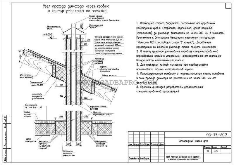
Features of installation of a typical design
Penetration units for ventilation communications of industrial production are performed in accordance with the requirements of GOST-15150. It is believed that the air temperature inside the communication pipe should not exceed 80 degrees, and the flow humidity should be within 60%.
The place where the ventilation pipe passes through the roof usually has a square configuration, this must be taken into account when choosing the shape of the duct and the type of transition node
To calculate the passage node, one should take into account such indicators as the angle of the slope of the slope and the distance from the element to the roof ridge.
A typical transition node can be made in the following variations:
- with or without condensate ring;
- with insulated or conventional valve or without valve;
- with manual or mechanical control for the valve;
- with or without spark protection, etc.
The options listed may vary depending on the situation. For example, it is not necessary to install a mechanical valve if the system is stable and does not need constant adjustment.It is also possible to manufacture a penetration unit on order.
Typical units for penetration through the roof, made at industrial enterprises, are very diverse, they are selected depending on the size of the pipe and the characteristics of the roof
Structures of this type are made of polymers, stainless steel 0.5-0.8 mm thick and black steel 1.5-2 mm thick. The cross section of the finished transition node can be round, oval, square or rectangular. A specific model is chosen depending on the type of roofing material and the parameters of the ventilation pipe.
Although foreign-made passage assemblies are usually of high quality, they are not always adapted to local climatic conditions, so it does not hurt to carefully study the offers of domestic manufacturers.
They are usually labeled as follows:
- the letters UE with an index from 1 to 10 indicate a design without a condenser ring and a valve;
- indexes from 2 to 10 indicate devices with a manual valve, the ring is missing;
- the designation of the UPZ is assigned to devices with a special platform for the actuator for the valve, which is provided for by the design.
The complete set of ready-made models of transition nodes includes embedded bolts and nuts that are attached to wooden structures, reinforced concrete cups intended for installation. Mineral wool is successfully used for thermal insulation, which is recommended to be protected with a layer of fiberglass.
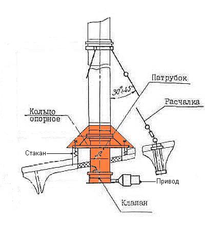
If it is necessary to install a ventilation unit with a safety valve, you should pay attention to the branch pipe intended for it. A valve must be attached to the bottom flange of this element.
The upper flange is designed to fix the position of the air duct.Clamps and brackets are used as fasteners for braces.
To further protect the ventilation riser from moisture, you need to use a skirt. The condensate collector is welded to the branch pipe.
It is designed to remove moisture from the air masses that move through the ventilation duct. To control the valve, a mechanical assembly is used, which should be installed on the shelf intended for it.


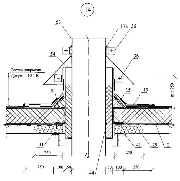


This element should not be installed next to the condensate collection ring in order to maintain the integrity of all penetration elements. Typical node models are usually mounted before the start of roofing work: first, the ventilation system ducts are mounted, then the passage, and the roof is placed after that.
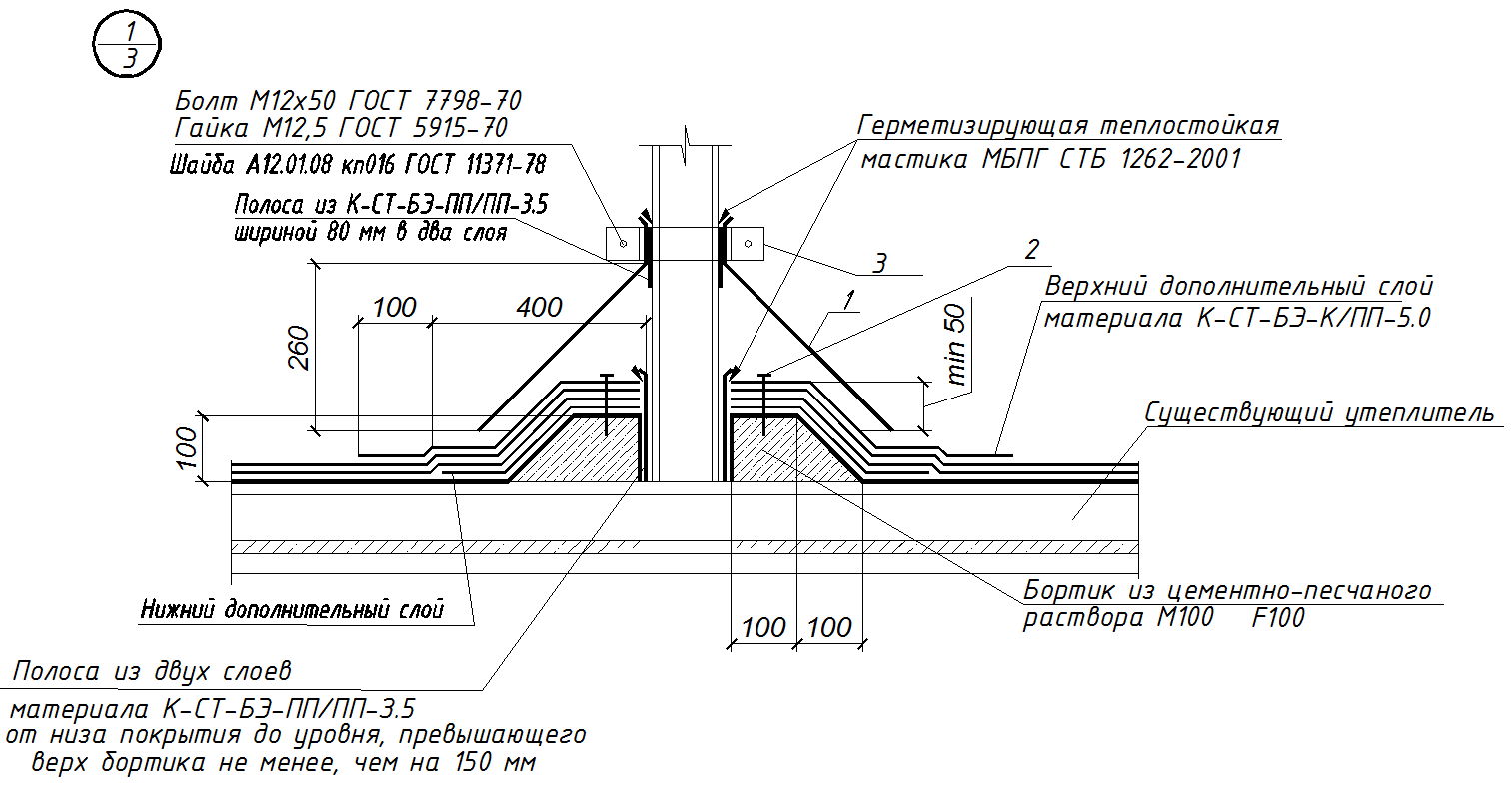
It is recommended that at the end of the work, all joints be sealed, including the junction of the assembly elements to the roofing.
For this you should:
- clean the surfaces of the pipe and roof from contamination;
- seal the lower part of the duct and the adjacent section of the roof with foil paper;
- fill holes with sealant.
These measures will help protect the penetration from moisture and create additional thermal insulation of the structure.
The article recommended by us will acquaint you with the rules for installing the ventilation system directly, in which the nuances of design and organization are analyzed in detail.
The subtleties of installing a ventilation network
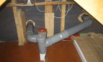
The scheme for laying ventilation networks should contain a minimum of connections. Air ducts are closed by two methods: flanged and flangeless.
Flange connection. Parts with flanges located at the edges are fastened with self-tapping screws or rivets, which are located at a distance of 20 cm from each other.For greater strength of the seams, they can also be brewed.
In order for the joints to be tight, it is recommended to seal the flanges with rubber gaskets.
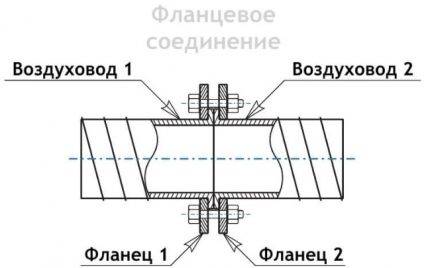 Scheme of assembling an air duct from several elements using the flange method. The elements that will be used to fasten the structure to the bearing surface are also indicated (+)
The flangeless method consists in connecting parts using a bandage made of metal rails. This method is considered more economical because it allows you to assemble the structure faster with minimal use of additional components.
What to pay attention to?
The assembly of the duct from rigid parts must be carried out in the following sequence:
- Before carrying out work, the system must be divided into several blocks. The length of each of them should not exceed 15 meters.
- On all details of the site - air ducts, fittings, connection points are marked.
- Holes of the required diameter are drilled at these points.
- Bolted fasteners are attached to them. Joints are treated with special adhesive tape or a sealing compound.
- Then, a complete installation of the connecting components and air ducts is carried out into a single unit, which is fixed with clamps and other details.
- The assembled block is lifted and hung on a bracket or other fixture.
- The element is connected to the previously completed ventilation section, while the joints are sealed along the diameter.
Installation of a system of flexible or semi-rigid elements is somewhat easier, since in this case it is easier to perform turns and bends
It is important not to forget to monitor the careful sealing of the seams
 The distance between the air duct fixings is 1.8 meters when the system is placed vertically and 1 meter when placed horizontally. Permissible rate of sagging of a flexible element is 5 cm per 1 meter
When assembling a system from flexible semi-rigid elements, it is necessary to pay attention to the following details:
before laying, a fully flexible element should be stretched;
when stretching the corrugated sleeve, it is important to observe the direction of air movement indicated on the pipe packaging;
when placing an air duct, it is necessary to avoid its proximity to heating systems;
the bending radius must correspond to or exceed twice the diameter of the duct;
fastening of sections is carried out using plastic clamps, foil tape, suspensions, clamps. All joints should be carefully sealed;
when laying the system through a wall, you need to use special adapters - sleeves. Installation of air ducts can be carried out both with and without insulation
Thermal insulation prevents condensation in the supply ducts, so it is recommended to perform it when laying ventilation elements in unheated rooms or outside buildings
Installation of air ducts can be carried out with or without insulation. Thermal insulation prevents condensation in the supply ducts, so it is recommended to perform it when laying ventilation elements in unheated rooms or outside buildings.


If the air duct is installed in a living room where it is desirable to observe a reduced noise level - an office, a bedroom, a nursery, you should think about sound insulation.A good effect is the use of air ducts with a large wall thickness, as well as wrapping structural elements with sound-absorbing materials.
How to bypass the pipe?
Pipe sewing is a way to cover the junction and, in some cases, the duct itself.
This is done for the following reasons:
- the appearance of the roof;
- despite compliance with the requirements for the height of the pipe, there is no draft;
- there is no certainty about the quality of the material from which the ventilation shaft is made, there are fears that it will collapse under the influence of precipitation.
Various materials are used to bypass the ventilation pipe. They vary in cost as well as in their characteristics.
The specific type of ventilation pipe is selected not only taking into account its characteristics, but also paying attention to the material with which the roof is covered
The most popular is galvanized material, which is coated with a polymer. This is the cheapest way to bypass the pipe, it is durable in use and has a presentable appearance. Since the ventilation pipe is not considered flammable, siding can be used to sheath it.
In some cases, it becomes necessary to bypass the ventilation pipe with soft tiles, which is reasonable only if the entire roof is made of such material.
The rules for laying flexible tiles do not differ when bypassing the ventilation pipe. At the same time, it is worth making sure that the joints of the tiles do not allow water to pass to the junction of the air duct, and also do not interfere with the free descent of precipitation from the roof.
General characteristics of roof ventilation units
When installing various technical communications, ventilation pipes are traditionally installed on the roof.This approach has specific features and requires scrupulous adherence to the installation technology.
The ventilation units of the passage in many cases have a similar design for various models. They are used for the forced and natural process of removing exhaust air, condensate, and fumes outside the building.
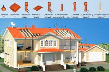 All types of roof penetrations must be impeccably made and sealed so that atmospheric dust and water do not penetrate into residential and utility rooms. According to the schemes of roof passages, not only ventilation pipes are equipped, but also aerators, and chimneys, and antennas, and roof hatches
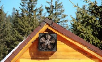
The ventilation pipe of the roof unit is positioned so that the exhaust air can escape unhindered.
For pitched roofs, a convenient solution would be to install a ventilation pipe next to the ridge. This design does not require additional reinforcement and the installation of a snow removal system.
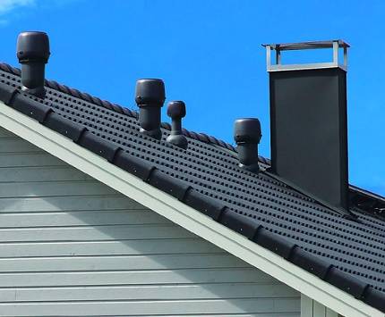
With the close location of the exhaust pipes to the ridge ridge, the least wind pressure is exerted on the system. However, for the formation of normal draft, the ventilation pipe (shaft) must be at least 0.5 m higher than the ridge. This requirement does not apply to aerators and roof fans that solve the problem of draining the roof cake
The manufacture of passage systems complies with GOST 15150, namely:
- The thickness of the material exceeds 1.9 mm.
- The diameter of the circle is 10-12.7 cm. For nodes with a square section, the dimensions may vary.
- Treated with anti-corrosion compounds.
- The size of the support ring necessarily exceeds the diameter of the nozzles.
- The length of the structure must be a maximum of 1 m.
The node itself can be placed on a reinforced concrete glass or directly on the roof section.
The consumer is now offered a wide range of universal and specialized devices for hermetic and operational design of roof passages, both for the internal ventilation system and for drying roof layers.
The dimensions and shape of the outlet are affected by the type of coating, its thickness and the special characteristics of the material, as well as the characteristics of the entire ventilation system. Its choice depends on the conditions created inside the building: the degree of humidity; dusty rooms; gassiness, etc.


Description and purpose of passage nodes
Under the node of the passage of ventilation through the roof (another name is quite common - roof penetration) is understood as a device that passes through the roofing and is designed to remove polluted air. Since the installation of the passage assembly violates the integrity of the roof covering, the installation should be approached with special care and accuracy. Otherwise, violations may occur both in the operation of the ventilation system and the roof. This, of course, can lead to their rapid failure and subsequent costly repair or replacement of individual structural elements.
The roof ventilation passage assembly can also be used to bring other building or structure systems to the roof, for example, chimneys (if there is a fireplace or stove in the house) or gas ducts (if there is a gas boiler or other similar equipment). At the same time, it must be taken into account that in the case of penetrations for chimneys, they should be equipped with additional fire-resistant elements (for example, a duct). This is due to the fact that the air temperature in the furnaces can reach 700-800 degrees, which leads to a strong heating of the pipe.
Work on the installation of roof penetrations must be carried out in accordance with the provisions of GOST 15150, which clearly spells out all the basic requirements for the structure and its location on the roof.
The ventilation outlet to the roof is a pipe of various profiles and sizes, which is inserted into a hole specially made for it in the floor or roof of the building. Depending on the type of roof, as well as the type of ceiling, various types of roof penetrations can be used.