- Kinds
- Autogas (gas generating) switch
- Vacuum high voltage circuit breaker
- SF6 HV
- The expediency of replacing with a vacuum
- Types of switches for home (domestic use)
- Unusual types of switches
- How oil circuit breakers are tested
- Malfunctions in the operation of oil switches and their elimination
- Maintenance of oil circuit breakers
- What to consider when choosing a device
- Why combine a knife switch with an "automatic"
- Operation of the short circuit without a separator
- Requirements for circuit breakers of special design
- Working in a tropical climate
- Shock and vibration resistance (marine)
- Circuit breakers with neutral current protection
- Tripping characteristics of protective circuit breakers
- Machine type MA
- Class A appliances
- Class B protective devices
- Automatic machines of category C
- Category D circuit breakers
- Protective devices of category K and Z
- The device and principle of operation of the short circuit.
- Purpose
- Short circuit and separator device
- Equipment classification
- Introduction to the oil circuit breaker
- Advantages and disadvantages
- Conclusions and useful video on the topic
Kinds
According to the method of extinguishing the arc in the chambers, HVs are divided into the following types:
- autogas;
- SF6;
- vacuum;
- air;
- oil;
- electromagnetic.
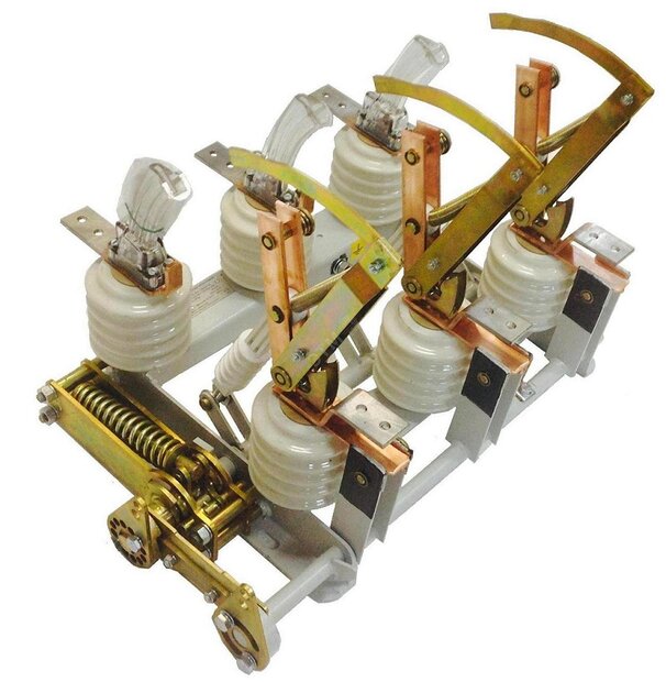
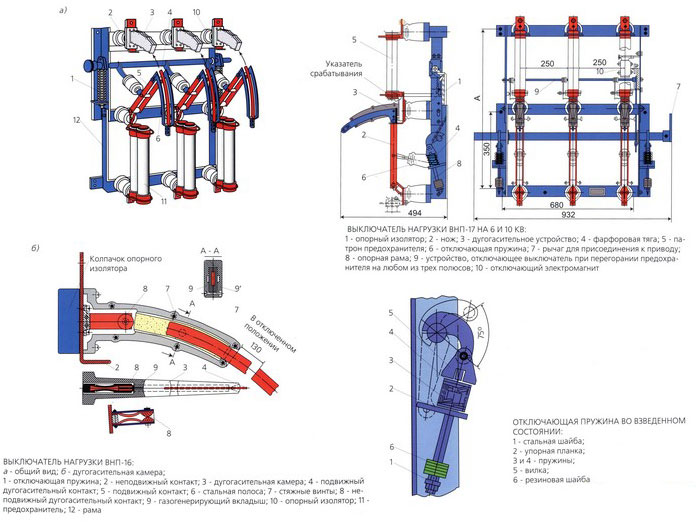
Autogas (gas generating) switch
The device is designed for operational switching of power electrical equipment. Arc suppression occurs under the action of gases generated in the extinguishing chamber. An insert made of urea-formaldehyde resin or polymethyl methacrylate, located inside the chamber, heats up at lightning speed when the arcing contacts are switched. Under the action of high temperature, the upper layer of the polymer evaporates, and the resulting gas flow intensively extinguishes the electric arc.
The condition for the liner to evaporate is created by arcing contacts, starting the process of "longitudinal blowing". In the on state, the rated current flows through the main contacts.
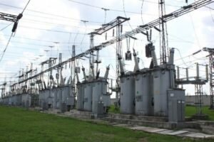
Autogas VNs are actively used in Russia and CIS countries. They are used at substations, installed in switchgears of 6-10 kV electrical networks with isolated neutral. Basically, they are mounted where it is not economically profitable to use installations of a different type, and the use of disconnectors is prohibited by the rules of the PUE.
This type of switches has the lowest cost and high maintainability. These advantages contribute to the growing popularity of gas generating circuit breakers.
Vacuum high voltage circuit breaker
A very effective, but expensive device that allows you to turn off not only the rated load currents, but also overcurrents in case of short circuit. The contacts of the vacuum switches are located in a vacuum chamber with ultra-low pressure (about 10-6 - 10-8 N/m). The absence of gas creates a very high resistance, which prevents the arc from burning.
When opening/closing the contacts, the arc still occurs (due to the formation of plasma from the vapors of the contact metal), but it almost instantly goes out, at the moment of passing through zero. Within 7 - 10 microns/s, vapors condense on the contact surfaces and on other parts of the chamber.
There are varieties:
- vacuum circuit breakers up to 35,000 V;
- devices for voltages exceeding 35 kV;
- vacuum contactors for networks of 1000 V and above.
Main advantages:
- switch operation in any position;
- switching wear resistance;
- stable work;
- Fire safety.
Among the shortcomings, one can single out a relatively high cost due to the complexity of the camera production technology.
SF6 HV
In switching devices of this type, SF6 gas is used to extinguish the arc. The device works on the principle of autogas switches, but instead of air, sulfur hexafluoride (SF6) with the addition of other gases is used to extinguish the arc.
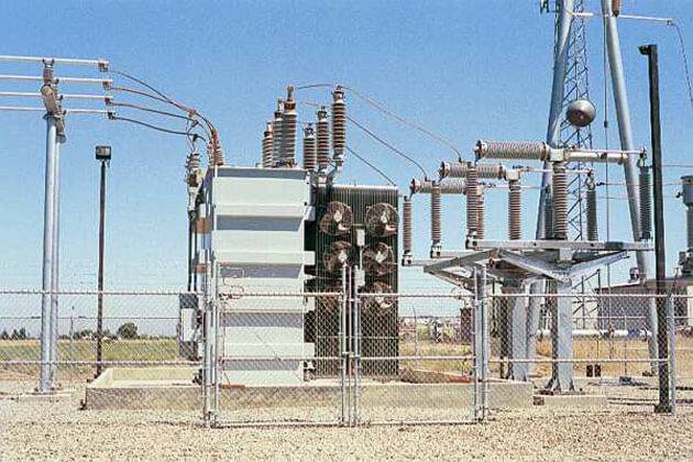
SF6 enters the body of the extinguishing chamber from a hermetic container, which is not emitted into the atmosphere, but is reused. There are column and tank devices (see Fig. 5).
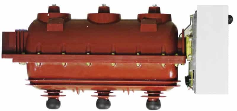
Rice. 5. Tank SF6 HV
The designs of such switches use built-in current transformers. Modern SF6 HVs can operate in ultra-high voltage switchgears, up to 1150 kV.
The expediency of replacing with a vacuum
Oil circuit breakers became most popular and widespread in the 20th century, in the 21st century they are all actively replaced by vacuum circuit breakers.
The latter have the following advantages:
- Significantly smaller dimensions and weight.
- High reliability.
- Ease of maintenance.
- Much easier and safer switching on and off.
- Much more resource.
Based on the above points, it becomes obvious that vacuum circuit breakers are superior in all respects compared to oil circuit breakers.
Of course, replacing an entire section of a substation, or an entire substation, from oil circuit breakers to vacuum circuit breakers is difficult: it is time consuming and expensive.
However, over a long distance of several decades, such an investment fully justifies itself.
Types of switches for home (domestic use)
Various types of switches used in everyday life should be convenient, safe, and have an attractive design. They differ from each other in types and types. According to the installation method, the switch can be built-in or installed outside. Nowadays, the rotary key is most often used as controls; such switches are common in Europe.
Types of switches for the home
In the USA, they prefer to use lever-type switches (toggle switches), apparently not wanting to deviate from tradition. But this is now, and in the old days, when Thomas Edison only made his invention, rotary switches were used. They were known all over the world in the first half of the 20th century and switched up to several circuits in 3-4 positions (packet switch). Batch switches are still used in many old utility shields.


To turn on the lamp, use a single-key switch; for chandeliers, a two-key or even a three-key switch is used. For rooms such as toilets and bathrooms, use a double light switch. We add that in our age of advanced technology, many switches with additional functions have appeared. These are the functions:
- illuminated switch for night time
- switch with off timer.
- Switches with brightness control.
If everything is clear with the first type of functions, then the second is used to save light in small rooms (pantries, bathrooms) where they enter for a short time and forget to turn off the light. And the third can be used together with those fixtures that support the dimmer function (dimmer). Sometimes they come as a set, since this type of device has not yet been standardized.
Unusual types of switches
Light switch with sensor movement is another way to save electricity, very convenient. The light turns on if the infrared sensor detects the movement of a person in the field of view of the sensor. Repeated movement may turn off the light, or a timer may do so after movement has been detected. The switch with a motion sensor does not require any action from a person, his presence is enough.
There is one so-called smart switch, this is the cotton switch. Since it reacts to noise, it can turn on involuntarily. Inside it is a microphone, it is also an amplifier and a microprocessor device in order to recognize the nature of the sound. It may not work the first time, as it remembers the sound from the user in memory for later comparison.
And such things happen
The floor switch is made in the form of a button with fixation. It can be turned on by pressing the foot with little effort, and the design is made in such a way that the weight of the foot does not damage it.
The ceiling switch is also a button with a latch, to which the force is transmitted from the lever, with a cord attached to it. The mechanics is hidden behind a decorative cover.To turn it on or off, you need to lightly pull on the cord.
How oil circuit breakers are tested
After repairs and scheduled maintenance of oil circuit breakers, high-voltage tests are mandatory. They include the supply of high voltage to the poles of the devices.
For oil circuit breakers with a voltage of 6 kV, most often 30-36 kV test voltage is supplied from a step-up transformer from a special laboratory.
The test voltage is applied for 5 minutes to each phase in turn (or immediately to 3 phases, if the design of the testing laboratory allows). If during this time the insulation withstands this voltage and no breakdown occurs, then the test is considered successful.
Also, before and after the test, the insulation resistance of each pole is measured, which should be 1.3 times greater than what it was before the test.
If the test is successful, the oil circuit breaker is put into operation, but if a breakdown occurs at some phase, then an inspection and, if necessary, repair is carried out (search for the place of breakdown, strengthening or replacing the insulation in this place).
After that, high voltage tests are again carried out until all three phases withstand the test voltage for a predetermined time.
Malfunctions in the operation of oil switches and their elimination
Malfunctions in the operation of oil circuit breakers lead to major accidents with the formation of fires in switchgears.
Frequent problems:
- failures of circuit breakers in switching off short-circuit currents;
- malfunctions of contact systems, overlapping of elements of internal and external insulation;
— breakage of insulating parts;
- failures of transmission mechanisms and drives.
The failure to turn off the current is due to the discrepancy between the actual breaking capacity of the circuit breakers and the conditions of their operation.
To prevent this, it is necessary to periodically check the compliance of the parameters of the switches with the real conditions of their operation.
In practice, such substation operation schemes should not be created in which the short-circuit power exceeds the breaking capacity of the circuit breakers.
In emergency and repair situations, if it is necessary to connect two or more bus systems for parallel operation (for example, by turning on sectional switches), this operation must be accompanied by measures that lead to limiting short-circuit currents.
Malfunctions of contact systems: non-inclusion of moving contacts, freezing of contacts in an intermediate position, destruction of cermets, breakage of socket contacts. This prevents opening and closing of the circuit breakers and leads to the formation of an arc with subsequent explosion of the circuit breaker.


Insulation flashovers occur during switching and lightning overvoltages and as a result of pollution of insulation by entrainment of industrial enterprises near the substation.
For circuit breakers of the VMG and VMP series, there are often cases of overlapping of the support insulation on a contaminated and moistened surface.
Failures in the operation of transmission and operating mechanisms and drives occur as a result of breakdowns of individual parts and violations of adjustment. This leads to jamming of shafts, sticking of rods and abnormal operation of contact systems, which leads to accidents.
The reasons for the failure of the drives are poor-quality adjustment, rubbing in the release mechanism and the cores of electromagnets, defects in the springs, and violations of the connections between the parts of the drive mechanism due to the loss of axes and fingers.
Maintenance of oil circuit breakers
After the circuit breaker has interrupted the short-circuit currents several times or the load currents several times, the contacts may burn out due to sparking. In addition, the dielectric oil chars near the contacts, thereby losing some of its dielectric strength. This leads to a reduction in the breaking capacity of the circuit breaker.
Therefore, maintenance of the oil circuit breaker requires inspection and replacement of contacts and oil. It is recommended to check the circuit breaker every 3 or 6 months. According to ISS 335-1963, oil in good condition must withstand 40 kV for one minute in a standard oil test cup with a gap of 4 mm between the spherical electrodes.
What to consider when choosing a device
When planning the purchase of a load switch, it should be remembered that the device is primarily intended not to protect electrical appliances, but to protect wiring from overheating, burnout and overvoltage. Therefore, in order for the purchase to be correct, and the device to cope with the tasks, it is necessary to first find out the cross section of the cable entering the apartment or house shield and the current level for which it is designed.
Vacuum type modules are gaining more and more popularity. They have small external dimensions and due to this they become convenient for embedding in various types of junction boxes.
When this information is obtained, it is compared with the factory characteristics of the switch-disconnector. The operating current indicator of the device should be slightly less than the maximum allowable current for the wire.
Vacuum load break switches are a progressive type of related electrical parts. It significantly increases the level of basic system safety, does not create combustion products and does not emit them into the atmosphere.
If the cable capacity is much higher than the current consumption of the load, consider purchasing an automatic module for load.
To determine the desired parameters of the device, first summarize the power of all electrical appliances in the living room. From 5 to 15% is added to the amount received for the reserve and, according to the formula of Ohm's law, the total total current consumption is determined. Then they buy an automatic machine that has a trip current slightly higher than the calculated one.
Why combine a knife switch with an "automatic"
At the household level, this ensures the convenience of managing the electrical network and the durability of the home electrical network, but the decision is still up to you. You plan to de-energize the line a few times a year, for example, only during emergency repairs? Then you can get by with the "automatic" lever.
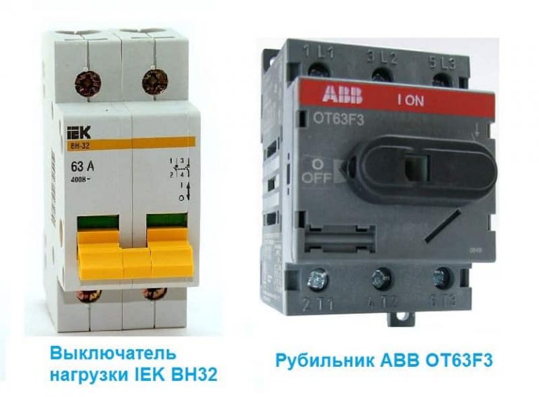
If we are talking about the electrical network of an apartment building or an industrial building, for which there are increased safety requirements. First of all, put a knife switch on the critical places on the input cable. It will work as a switching device, with the help of which the line is de-energized with one movement. Moreover, the device must be with a visible open circuit, without protective covers.
For example, the P2M model from Elecon for 250A or the PE19 series disconnector from IEK, in which, when the network is turned off with a lever, a break in the contacts is visually noticeable - there are no covers and panels that obscure the interior of the structure. For what? So that when maintaining the network at the facility, the person conducting the work is 100% sure that the system is de-energized. And the design of the “machine” cannot provide this visual clarity, because the body of the device is closed.
The use of circuit breakers is advisable in industries where personnel at the end of the working day or before carrying out repair work must de-energize the equipment. Or, for example, to turn on and off the perimeter lighting system.
Operation of the short circuit without a separator
Below is a circuit diagram of a substation where a short circuiter is used without using a separator.
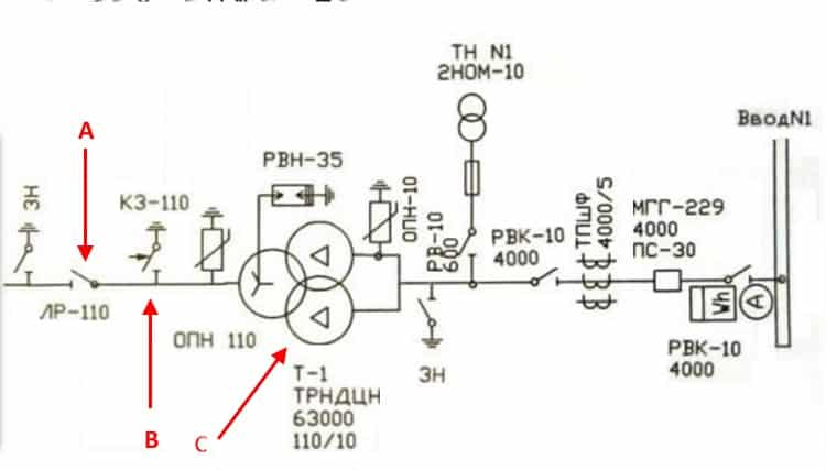
Substation diagram 110/10
Meaningful designations:
- A - Line breaker in the high-voltage part of the transformer substation.
- B - Short circuit.
- C - Power transformer.
In this circuit, the short circuit will work as follows:
- If there are problems with the transformer "C", it sends a signal to the short circuit "B".
- The mechanism of the electromechanical device produces a short-circuited connection.
- Short circuit monitors the relay protection, and generates a signal on the LR "A".
- The power switch trips and cuts off the input.
After the cause of the protection operation is established and eliminated, the switch is turned off (that is, the input line is connected).
The above-described example of organizing protection at a substation is quite efficient and reliable, but the use of a circuit breaker in this case does not justify itself due to its high cost.
Requirements for circuit breakers of special design
Working in a tropical climate
Circuit breakers and additional elements of climatic version T, TV, TC (tropical, tropical humid and tropical dry) are tested in accordance with IEC 60068-2-30 by performing 2 operating cycles at 55 °C. Structurally, the suitability of circuit breakers for operation in hot and humid climates is ensured by:
- molded insulating housing made of synthetic resins reinforced with fiberglass;
- anti-corrosion treatment of the main metal parts;
- galvanized Fe/Zn 12 (ISO 2081) with a hexavalent chromium-free protective layer with the same corrosion resistance according to ISO 4520, class 2c;
- application of special anti-condensation protection for electronic trip units and related accessories.
Shock and vibration resistance (marine)
M climatic circuit breakers withstand vibrations caused by mechanical or electromagnetic influences, the magnitude of which is regulated by the IEC 60068-2-6 standard, as well as the technical specifications of the following organizations:
- RINA;
- Det Norske Veritas;
- Bureau Veritas;
- Lloyd's Register;
- Germanischer Lloyd;
- Nippon Kaiji Kyokai;
- Korean Register of Shipping;
- ABS;
- Russian Maritime Register of Shipping.
According to the IEC 60068-2-27 standard, circuit breakers are also tested for shock resistance up to 12 g for 11 ms.
Circuit breakers with neutral current protection
The design of circuit breakers with neutral current protection is used in special cases where the presence of the third harmonic on individual phases can lead to a very high current in the neutral. Typical applications include: installations with high harmonic distortion loads (thyristor converters, computers and electronic devices in general), lighting systems with a large number of fluorescent lamps, systems with inverters and rectifiers, uninterruptible power supply (UPS) systems, and systems for speed control of electric motors.


Tripping characteristics of protective circuit breakers
Class AB, determined by this parameter, is indicated by a Latin letter and is affixed on the body of the machine in front of the number corresponding to the rated current.
In accordance with the classification established by the PUE, circuit breakers are divided into several categories.
Machine type MA
A distinctive feature of such devices is the absence of a thermal release in them. Devices of this class are installed in the connection circuits of electric motors and other powerful units.
Class A appliances
Automata type A, as was said, have the highest sensitivity. The thermal release in devices with time-current characteristic A most often trips when the current exceeds the nominal value AB by 30%.
The electromagnetic trip coil de-energizes the network for approximately 0.05 seconds if the electric current in the circuit exceeds the rated current by 100%. If, for any reason, after doubling the strength of the electron flow, the electromagnetic solenoid does not work, the bimetallic release turns off the power within 20 - 30 seconds.
Automatic machines with a time-current characteristic A are included in the lines, during which even short-term overloads are unacceptable. These include circuits with semiconductor elements included in them.
Class B protective devices
Category B devices are less sensitive than those of type A. The electromagnetic release in them is triggered when the rated current is exceeded by 200%, and the response time is 0.015 seconds. The operation of a bimetallic plate in a circuit breaker with characteristic B, with a similar excess of the AB rating, takes 4-5 seconds.
Equipment of this type is intended for installation in lines that include sockets, lighting devices and in other circuits where there is no starting increase in electric current or has a minimum value.
Automatic machines of category C
Type C devices are most common in household networks. Their overload capacity is even higher than those previously described. In order for the electromagnetic trip solenoid installed in such a device to operate, it is necessary that the flow of electrons passing through it exceeds the nominal value by 5 times. The operation of the thermal release when the rating of the protection device is exceeded five times occurs after 1.5 seconds.
The installation of circuit breakers with a time-current characteristic C, as we said, is usually carried out in domestic networks. They perfectly cope with the role of input devices for protecting the general network, while category B devices are well suited for individual branches to which groups of outlets and lighting devices are connected.
Category D circuit breakers
These devices have the highest overload capacity.For the operation of an electromagnetic coil installed in an apparatus of this type, it is necessary that the current rating of the circuit breaker be exceeded by at least 10 times.
The operation of the thermal release in this case occurs after 0.4 sec.
Devices with characteristic D are most often used in general networks of buildings and structures, where they play a safety net. Their operation occurs if there is no timely power outage by circuit breakers in separate rooms. They are also installed in circuits with a large amount of starting currents, to which, for example, electric motors are connected.
Protective devices of category K and Z
Automata of these types are much less common than those described above. Type K devices have a large variation in the current required for electromagnetic tripping. So, for an alternating current circuit, this indicator should exceed the nominal value by 12 times, and for a constant current - by 18 times. The electromagnetic solenoid is activated in no more than 0.02 seconds. The operation of the thermal release in such equipment can occur when the rated current is exceeded by only 5%.
These features determine the use of type K devices in circuits with an exclusively inductive load.
Type Z devices also have different actuation currents of the electromagnetic trip solenoid, but the spread is not as large as in category K AB. 4.5 times more than the nominal.
Devices with characteristic Z are used only in lines to which electronic devices are connected.
Clearly about the categories of slot machines in the video:


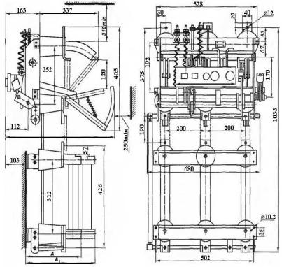
The device and principle of operation of the short circuit.
Figure 1. Construction
Figure 2. Buffer
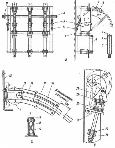
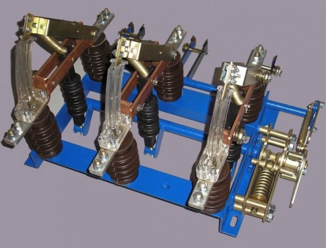
Structurally, the short circuiter (Fig. 1) consists of a base 3, an insulating column 2, on which a fixed contact 1 is fixed, a grounding knife 8. The base 3 of the short circuiter is unified and is a welded structure designed to install an insulating column with a fixed contact. Bearings are located in the walls of the short-circuiter base, in which the shaft rotates with welded levers, two of which are connected to springs, and one lever interacts with an oil buffer that serves to dampen the energy of the short-circuit moving parts at the end of switching on. Each of the two springs, with the help of a spring holder, is connected at one end to the shaft lever, and at the other - to the base. The location of the springs at the base provides protection from precipitation and ice. The fixed contact consists of a contact holder and a contact. The contact holder is made in the form of a tray, which serves to fasten the fixed contact to the insulating column. The oil buffer (Fig. 2) consists of a cup 6, inside of which there is a piston 3 and a rod 4. The return of the piston to its original position after the buffer is triggered is provided by a spring 1. The buffer cup is filled with oil (AMG-10 GOST 6794-75). The oil level is controlled by a dipstick through the hole for bolt 5, and should be 30 - 50 mm above the piston above the piston in the upper extreme position.When the short-circuit switch is turned on, the lever hits the buffer rod 4 and moves the piston 3 down, as a result of which the oil flows into the upper cavity through the gap between the hole in the piston 3 and the screw 22. the downward movement of the piston is rapidly reduced, which ensures effective braking. In the upper part of the buffer, to prevent the shaft lever from hitting the flange, there are rubber washers with a steel washer superimposed on them, which are attached to the flange body with two bolts 5. The damping capacity of the buffer is adjusted by screw 2. The short-circuiting knife is made of an aluminum alloy pipe reinforced with a stiffening rib. A tire is welded into the groove of the pipe, to which a removable contact plate is attached with four bolts. The lower end of the knife is fixed in the holder with two bolts. An insulating gasket is installed between the knife and the holder, which provides isolation of the current-carrying circuit from the base of the short circuit. The contact terminal for connecting the ground bus is fixed on an insulating gasket made of fiberglass. In the circuit of the grounding bar of the short circuit, a current transformer of the TSHL-0.5 type is installed to ensure joint operation with the separator. After turning on the short circuit, the current flows through the following circuit: supply bus - fixed contact - ground nom - flexible connection - ground bus passed through the window of the current transformer - earth.
Forward
Purpose
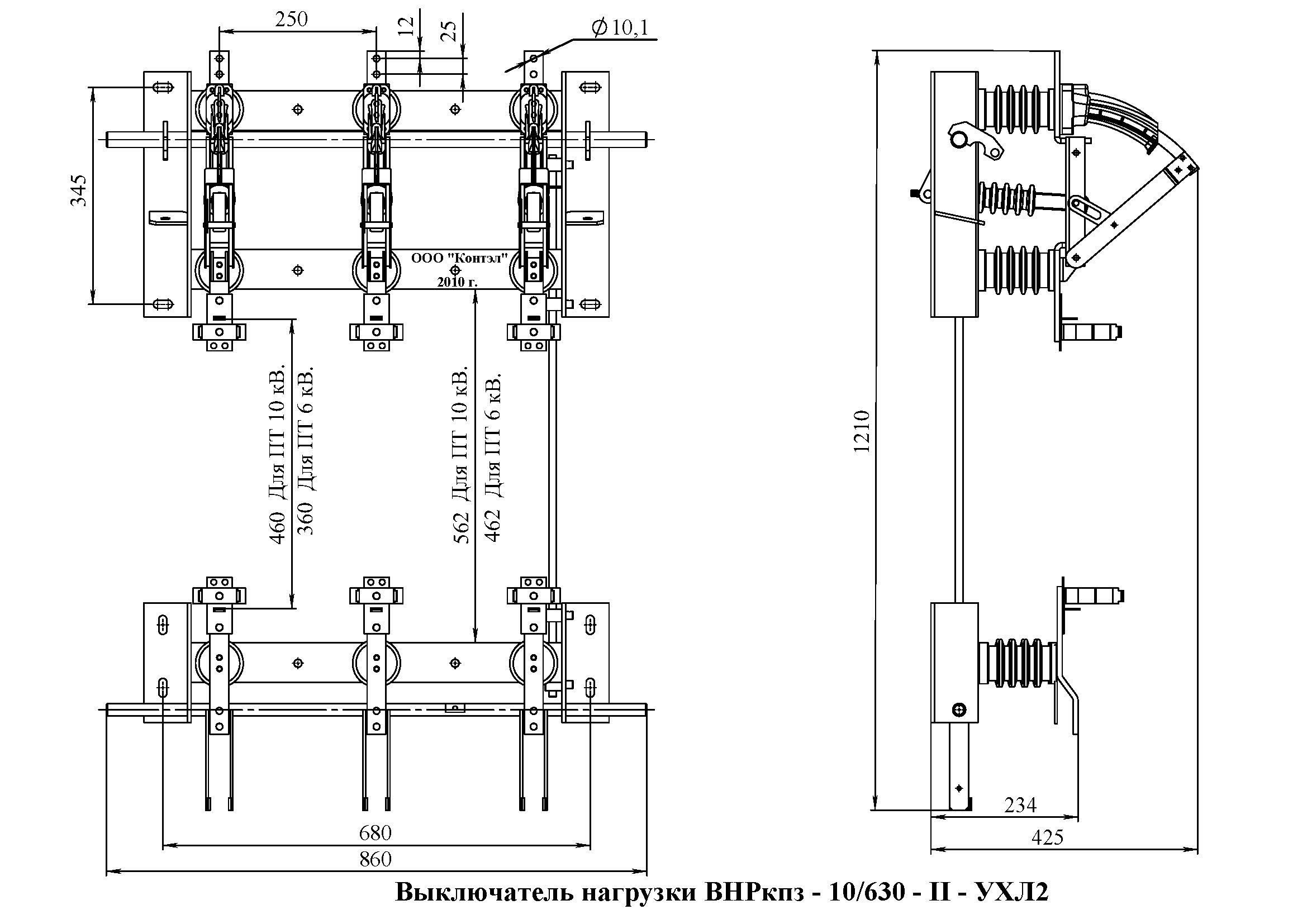
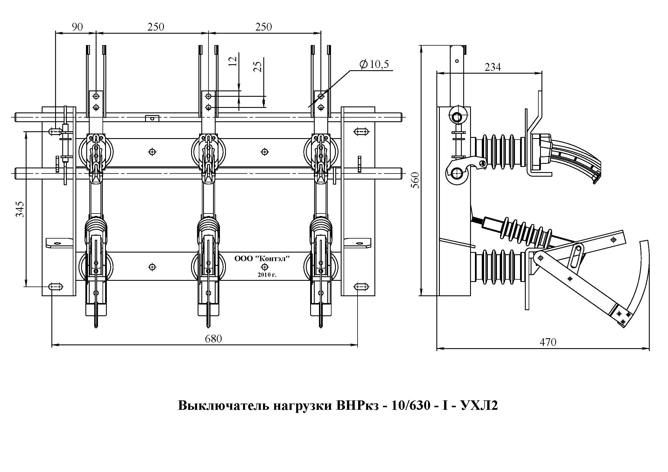
The purpose of the HV is the switching of operating currents in electrical installations, that is, powers that do not exceed the permissible (nominal) values for a particular section of the electrical network. This device is not designed to switch off emergency mode currents, therefore it can only be installed if there is protection against short circuit and overload in the circuit, which is implemented by fuses (PK, PKT, PT) or a protective device installed on the side of the power source or on the group consumers.
At the same time, the HV has a breaking capacity that corresponds to the electrodynamic resistance in case of short circuits, which allows using this electrical device to supply voltage to a section of the electrical network, regardless of its current state, for example, for trial switching.
Thus, subject to the presence of overcurrent protection in the circuit, the item of equipment under consideration can be operated as a full-fledged high-voltage protective device (oil, vacuum or gas-insulated). And in the presence of a motor drive, it can participate in the operation of various automatic devices (ATS, APV, ACR, CHAPV), as well as be controlled remotely by an automated system of dispatching technological control.
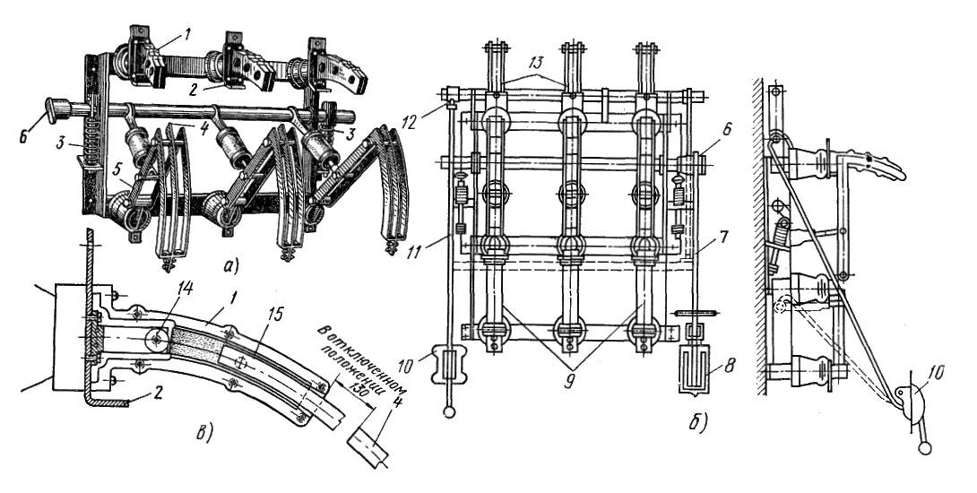
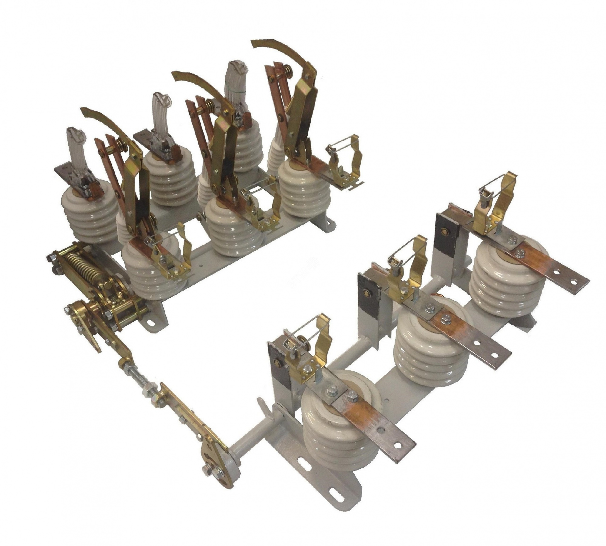
Short circuit and separator device
Briefly describe the design of the electromechanical devices shown above, it will be useful in explaining their principle of operation. Let's start with the separator, its simplified drawing is presented below (Fig. 3 1).
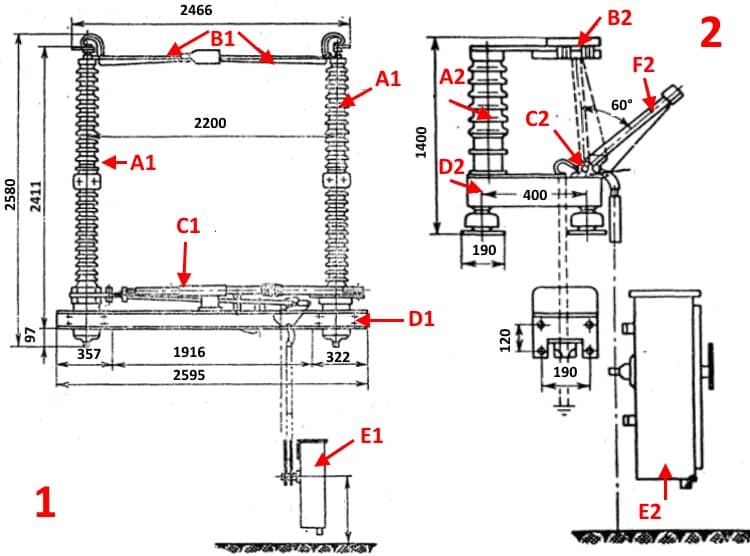
Figure 3. 1) separator design; 2)short circuit design
Designations (part 1 separator design):
- A1 - insulator racks.
- B1 - swivel bars with knife contacts installed.
- C1 is a spring mechanism that drives the swivel rods.
- D1 is the platform.
- E1 - a cabinet with an electromagnetic "trigger" mechanism that releases a spring drive that separates the contact parts.
Both the devices themselves and the mechanics of their work are not complex. We have already mentioned that the use of the separator is carried out when the mains is de-energized, that is, when the switches on the supply line are turned on. Therefore, it is possible not to install special vacuum interrupters.
Now consider the main structural elements of the short circuit (Fig. 3 2):
- A2 - main (support) insulator rod.
- B2 - fixed bar with contact knives.
- C2 - spring drive.
- D2 is the platform on which the short circuit is installed.
- E2 - cabinet for electromagnetic drive and current transformer.
- F2 is a movable grounded rod that closes the poles of the short circuit.
Structurally, the short circuiter KZ-35, as well as other models that create an artificial phase-to-phase short circuit, have several differences from the device shown in the figure. Since a linear circuit is simulated, the mobile is not connected to the "ground", it is connected to another phase. Accordingly, the design is equipped with another insulator-rack.
Equipment classification
To ensure the stable operation of electrical equipment, the following types of oil circuit breakers can be used:
- A system with a large capacity and oil in it is a tank system.
- Using dielectric elements and a small amount of oil - low oil.
The oil circuit breaker circuit has a special device for extinguishing the arc formed during a circuit break.According to the principle of operation of arc extinguishing devices, such equipment is divided into the following groups:
- Using forced air blowing working environment. Such a device has a special hydraulic mechanism for creating pressure and supplying oil at the point of breaking the chain.
- Magnetic quenching in oil is carried out using special electromagnet elements that create a field that moves the arc into narrow channels to break the created circuit.
- Oil switch with auto blow. The scheme of this type of oil switch provides for the presence of a special element in the system, which releases energy from the formed arc to move oil or gas in the tank.
Introduction to the oil circuit breaker
An oil switch is a switching device designed to turn on and off high-voltage power circuits and electrical equipment under load and without it.
This process of breaking the electrical circuit is carried out by the circuit breaker by opening the power contacts immersed in transformer oil. Due to this, the electric arc between them is extinguished, i.e. oil serves as an arc quenching medium.


During the shutdown process, a very high temperature rises in the oil, in the order of 6,000 °C. But the release of heat during combustion does not harm this electrical switching device due to the properties of the oil and the chemical reaction with vapors.
Advantages and disadvantages
The considered switching devices have strengths and weaknesses.
Benefits include:
- lower cost compared to other types of switches;
- fast and reliable switching on and off of rated load currents;
- the possibility of using cheap fuses for protection against overloads;
- the presence of a visible break in the contacts of high-voltage high-voltage voltages, which makes it possible to dispense with an additional disconnector.
Flaws:
- limited service life;
- circuit break is possible only for currents within the rated power values;
- After the fuse has blown, it must be replaced.
Conclusions and useful video on the topic
Learn more about load break switches in the videos below, where experts share their experience and installation nuances.
Features of installation of the switch of loadings. Step by step instructions from the master.
A detailed and understandable description, the rules for correct use and the direct purpose of the device from a professional electrician.
An overview of the modular load break switch manufactured by Hyundai. With this device, you can inexpensively solve the problem of switching an electrical circuit.
Features of the functioning of the load switch VN32-100 and the practice of using this device as a switch in electrical circuits of alternating 50-60 Hz current with a rated mains voltage of 230-400V.
A practical and reliable load switch helps to increase the level of safety in the operation of the electrical network and helps to open the current circuit in the right place and eliminate the breakdown or replace the failed equipment. The presence of a switch ensures the safety of intra-house or intra-apartment wiring, protects it from premature wear and significantly increases its service life.


