- Tables of letters for radio components
- 2 Normative references
- The letter designation of radio elements in the scheme
- Types and designations of relay contacts
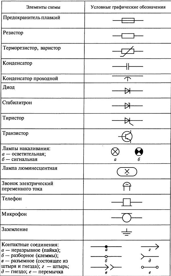
- Graphic symbols in electrical circuits
- Luminaires on the diagrams
- Species and types
- 1 area of use
- LETTER-NUMERIC DESIGNATIONS IN ELECTRICAL DIAGRAM
- Graphic and letter symbols in electrical circuits
- Types and meaning of lines
- Conclusion
Tables of letters for radio components
It's not about that now. Type 1 - functional diagram The functional diagram does not contain details, it indicates the main blocks and nodes.
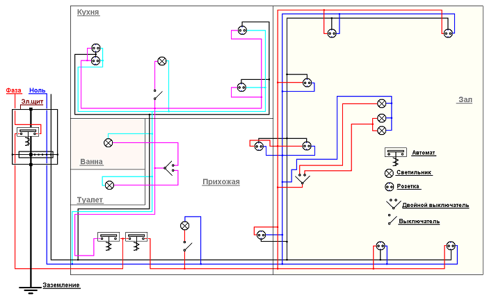
Schematic representation of various types of sockets - hidden built-in and open invoices. Next to the letter designation of the element is often its serial number.
Within groups, devices are divided by the number of poles, the presence of protection.
Within groups, devices are divided by the number of poles, the presence of protection. The standard includes 64 GOST documents, which reveal the main provisions, rules, requirements and designations. All this is also displayed graphically. V is an electricity icon representing alternating voltage.
A bell on an electrical circuit according to UGO standards with a designated size UGO dimensions in electrical diagrams On the diagrams, the parameters of the elements included in the drawing are applied. Types and types.

It also helps to read diagrams. The construction of the designation should provide the ability to unambiguously indicate the place of any part of the object in the design. The designation of an element generally consists of three parts indicating the type of element, its number and function.
Power varies from 0. The standardized and most commonly used ERE graphic symbols in circuit diagrams are shown in fig.
With a spaced representation method, it is allowed to add a conditional number of images of a part of an element or device to the number, separating it with a dot. Specifying an element's function does not identify the element and is optional. But let's start a little from afar After the definition, the document contains the rules for the implementation on paper and in software environments of the designations of contact connections, wire marking, lettering and graphic representation of electrical elements.
how to learn to read diagrams
2 Normative references
Any part can be represented as a block with a letter designation, supplemented with links to other elements of the device. In general, normative literature is studied in the course of work, design. The issues of placing electrical equipment in domestic premises, in the premises of workshops, substations, etc. are often considered. General designation.
Two-pole three-position switch with self-return to neutral position 5.
At the base of the movable part of the contacts, it is allowed to put a non-blackened dot (Fig.With a small distance between devices having a mechanical connection, where it is impossible to depict a mechanical connection line with a dashed line, it can be depicted as two solid parallel lines.
Designation of different types of rotational movement Rotational movement in one direction or another - according to fig.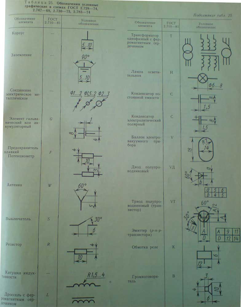
Images of contacts are allowed to be depicted in a mirror-rotated position: closing fig. Letter designations Along with the UGO, for a more accurate definition of the name and purpose of the elements, a letter designation is applied to the diagrams.
ZQ quartz filter Ordinal numbers should be assigned to elements, starting from one, within a group of elements that are assigned the same letter designation on the diagram, for example, Q1, Q2, Q3, in accordance with the sequence of their location on the diagram from top to bottom and from left to right. Image of the receiving part of electromechanical devices.
The text of the regulation sets out clear requirements in detail for electrical circuits of all types.
Elements of electrical circuits. Relay.
The letter designation of radio elements in the scheme
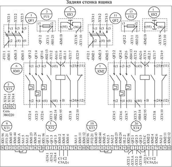
Let's take a look at our diagram again.
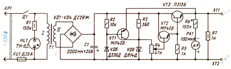
As you can see, the scheme consists of some obscure icons. Let's take a look at one of them. Let it be the R2 icon.
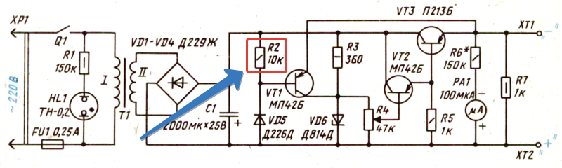
So, let's deal with the inscriptions first. R stands for resistor. Since he is not the only one in our scheme, the developer of this scheme gave him the serial number “2”. There are 7 of them in the scheme. Radio elements are generally numbered from left to right and top to bottom. A rectangle with a dash inside already clearly shows that this is a fixed resistor with a power dissipation of 0.25 watts. Also next to it is written 10K, which means its face value is 10 Kiloom.Well, something like this...
How are the other radioelements designated?
To designate radio elements, single-letter and multi-letter codes are used. Single-letter codes are the group to which this or that element belongs. Here are the main groups of radio elements:
A - these are various devices (for example, amplifiers)
B - converters of non-electric quantities into electrical quantities and vice versa. This may include various microphones, piezoelectric elements, speakers, etc. Generators and power supplies are not included here.
C - capacitors
D - integrated circuits and various modules
E - different elements that do not fall into any group
F - arresters, fuses, protective devices
G - generators, power supplies,
H - indicating devices and signaling devices, for example, sound and light indication devices
K - relays and starters
L - inductors and chokes
M - engines
P - instruments and measuring equipment
Q - switches and disconnectors in power circuits. That is, in circuits where a large voltage and a large current “walk”
R - resistors
S - switching devices in control, signaling and measurement circuits
T - transformers and autotransformers
U - converters of electrical quantities into electrical, communication devices
V - semiconductor devices
W - microwave lines and elements, antennas
X - contact connections
Y - mechanical devices with electromagnetic drive
Z - terminal devices, filters, limiters
To clarify the element, after the one-letter code comes the second letter, which already indicates the type of element. Below are the main types of elements along with the group letter:
BD - ionizing radiation detector
BE - selsyn-receiver
BL - photocell
BQ - piezoelectric element
BR - speed sensor
BS - pickup
BV - speed sensor
BA - loudspeaker
BB - magnetostrictive element
BK - thermal sensor
BM - microphone
BP - pressure sensor
BC - selsyn sensor
DA - analog integrated circuit
DD - integrated digital circuit, logic element
DS - information storage device
DT - delay device
EL - lighting lamp
EK - heating element
FA - instantaneous current protection element
FP - current protection element of inertial action
FU - fuse
FV - voltage protection element
GB - battery
HG - symbolic indicator
HL - light signaling device
HA - sound alarm device
KV - voltage relay
KA - current relay
KK - electrothermal relay
KM - magnetic starter
KT - time relay
PC - impulse counter
PF - frequency counter
PI - active energy meter
PR - ohmmeter
PS - recording device
PV - voltmeter
PW - wattmeter
PA - ammeter
PK - reactive energy meter
PT - hours
QF - circuit breaker
QS - disconnector
RK - thermistor
RP - potentiometer
RS - measuring shunt
RU - varistor
SA - switch or switch
SB - push button switch
SF - circuit breaker
SK - temperature switches
SL - level switches
SP - pressure switches
SQ - position switches
SR - speed switches
TV - voltage transformer
TA - current transformer
UB - modulator
UI - discriminator
UR - demodulator
UZ - frequency converter, inverter, frequency generator, rectifier
VD - diode, zener diode
VL - electrovacuum device
VS - thyristor
VT - transistor
WA - antenna
WT - phase shifter
WU - attenuator
XA - current collector, sliding contact
XP - pin
XS - socket
XT - detachable connection
XW - high frequency connector
YA - electromagnet
YB - electromagnetic brake
YC - electromagnetically driven clutch
YH - electromagnetic plate
ZQ - quartz filter
Types and designations of relay contacts
Relay contact designations
Depending on the design of the relay, there are three types of contacts:
- Normally open. They open before current flows through the relay coil. The letter designation is HP or NO.
- Normally closed. They are in the closed position until current flows through the relay coil. Designated with the letters NC or NC.
- Changeover/switching/general. They are a combination of normally open or normally closed contacts. They are equipped with a common switching drive. Letter symbols - COM.
To date, relays with changeover contacts are common.


Graphic symbols in electrical circuits
In terms of graphic symbols in electrical circuits, GOST 2.702-2011 refers to three other GOSTs:
- GOST 2.709-89 "ESKD. Conventional designations of wires and contact connections of electrical elements, equipment and sections of circuits in electrical circuits.
- GOST 2.721-74 "ESKD. Conditional graphic designations in schemes. General purpose designations»
- GOST 2.755-87 "ESKD. Conditional graphic designations in electrical circuits. Switching devices and contact connections.
Graphical symbols (UGO) of automata, knife switches, contactors, thermal relays and other switching equipment that is used in single-line diagrams of electrical panels are defined in GOST 2.755-87.
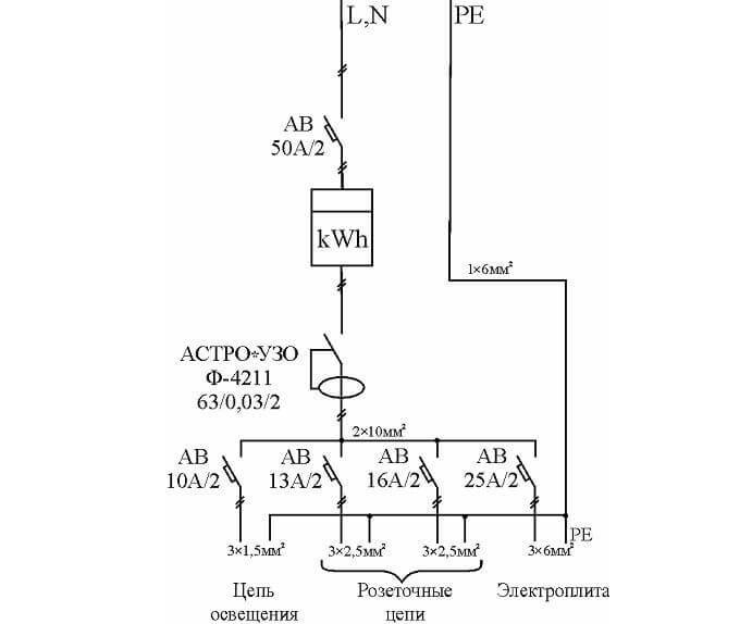
However, the designation of RCDs and difavtomatov in GOST is missing. I think that soon it will be reissued and the RCD designation will be added. In the meantime, each designer depicts an RCD according to his own taste, especially since GOST 2.702-2011 provides for this. It is enough to give the UGO designation and its decoding in the explanations to the diagram.
In addition to GOST 2.755-87, for the completeness of the scheme, you will need to use images from GOST 2.721-74 (mainly for secondary circuits).
All designations of switching devices are based on four basic images:
using nine functional features:
| Name | Image |
| 1. Contactor function | |
| 2. Switch function | |
| 3. Isolator function | |
| 4. Switch-disconnector function | |
| 5. Automatic actuation | |
| 6. Function of limit switch or limit switch | |
| 7. Self-return | |
| 8. No self-return | |
| 9. Arc extinguishing | |
| Note: The designations given in paragraphs. 1 - 4, 7 - 9, are placed on fixed contacts, and the designations in paragraphs. 5 and 6 - on moving contacts. |
The main conventional graphic symbols used in single-line diagrams of electrical panels:
| Name | Image |
| Circuit breaker (automatic) | |
| Load switch (knife switch) | |
| contactor contact | |
| Thermal relay | |
| RCD | |
| Differential machine | |
| Fuse | |
| Circuit breaker for motor protection (circuit breaker with built-in thermal relay) | |
| Switch-disconnector with fuse (breaker with fuse) | |
| Current transformer | |
| voltage transformer | |
| Electrical energy meter | |
| Frequency converter | |
| Normally closed contact of a pushbutton switch without self-resetting with opening and resetting of the control element automatically | |
| Normally closed contact of a non-self-resetting pushbutton with opening and return of the operating element by pressing the button again | |
| Normally closed contact of a non-self-resetting pushbutton with opening and resetting of the operating element by pulling the pushbutton | |
| Normally closed contact of a non-self-resetting pushbutton with opening and resetting of the operating element by means of a separate drive (e.g. pressing a reset button) | |
| Closing contact with deceleration active when triggered | |
| Normally open contact with deceleration active on return | |
| Closing contact with deceleration active during operation and return | |
| N/C contact with deceleration acting upon operation | |
| N/C contact with deceleration acting on return | |
| Closing contact with deceleration active during operation and return | |
| Contactor coil, general designation of relay coil | |
| Pulse relay coil | |
| photorelay coil | |
| Timing relay coil | |
| motor drive | |
| Lighting lamp, light indication (bulb) | |
| Heating element | |
| Detachable connection (socket): socket-pin | |
| Discharger | |
| Surge arrester (SPD), varistor | |
| Collapsible connection (terminal) | |
| Ammeter | |
| Voltmeter | |
| Wattmeter | |
| Frequency meter |
The designation of wires, tires in electrical panels is determined by GOST 2.721-74.
| Name | Image |
| Electric communication line, wires, cables, tires, group communication line | |
| The protective conductor (PE) may be shown as a dash-dotted line | |
| Graphic branching (merging) of group communication lines | |
| Intersection of electrical communication lines, group communication lines of electrically unconnected wires, cables, buses, electrically not connected | |
| Electrical communication line with one branch | |
| Electric communication line with two branches | |
| Bus (if necessary, graphically separated from the image of the electrical communication line) | |
| Bus branch | |
| Busbars that overlap graphically and are not electrically connected | |
| Taps (braces) from the bus |
Luminaires on the diagrams
This section describes the conventions in electrical diagrams. various lamps and fixtures. Here the situation with the designations of the new element base is better: there are even signs for LED lamps and fixtures, compact fluorescent lamps (housekeepers). It is also good that the images of lamps of different types are significantly different - it is difficult to confuse. For example, lamps with incandescent lamps are depicted in the form of a circle, with long linear fluorescent lamps - a long narrow rectangle. The difference in the image of a linear lamp of a fluorescent type and an LED one is not very big - only dashes at the ends - but even here you can remember.

Image of lamps (incandescent, LED, halogen) and fixtures (ceiling, built-in, hanging) on the diagrams
The standard even has symbols in electrical diagrams for ceiling and pendant lamps (cartridge). They also have a rather unusual shape - circles of small diameter with dashes. In general, this section is easier to navigate than others.
Species and types
Wiring diagrams are special drawings that indicate certain connections between electrical elements and devices that are connected to the network and consume electricity. The connection is described and organized according to standards and rules that are defined and operate according to physical laws. The scheme is designed to teach electricians and other specialists to understand the principle of network structure and the structure of devices, what parts it consists of.
Important! The main purpose of wiring diagrams is to help install and configure electrical devices, repair them based on quick and easy troubleshooting. To delve into the topic, you should understand what types of wiring diagrams exist and according to what principles they are separated, what are their characteristic features. Wiring diagrams, like documents, are divided into several types and types, divided according to some standards
First of all, you need to disassemble the main types of electrical circuits, which are:
Wiring diagrams, like documents, are divided into several types and types, divided according to some standards. First of all, you need to disassemble the main types of electrical circuits, which are:
To delve into the topic, you should understand what types of wiring diagrams exist and according to what principles they are separated, what are their characteristic features. Wiring diagrams, like documents, are divided into several types and types, divided according to some standards. First of all, you need to disassemble the main types of electrical circuits, which are:
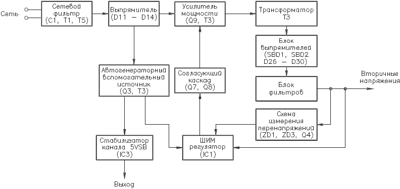
- Structural. The simplest option, which in the simplest "words" makes it clear how this or that device works, what it consists of.The reading order of such documents is indicated by arrows from block to block, and incomprehensible moments are indicated by explanatory inscriptions;
- Mounting. Often used in manuals or online resources, where it is proposed to install electrical wiring or other elements on your own. In such a diagram, you need to show the exact location of each individual element of the circuit (sockets in the house, and so on);
- United. As the name implies, this document combines several types and types of schemes. Typically, such electrical circuits are used in the case where, without a huge number of different elements, all important features of the circuit can be shown;
- Location schemes. Documents defining the relative location of some components of the product or electrical installation, and, if necessary, also bundles (wires, cables), pipelines, light guides, etc.;
- General. Those that define the parts that make up the complex, as well as their compounds;
- Functional. Not much different from the structural ones, but they describe in more detail all the components and nodal elements of the network. They no longer have obvious connections and components;
- Fundamental. Most often used in distribution networks, as they give an accurate understanding of how a particular electrical equipment works. On such diagrams, all the functional blocks of the chain and the types of connections between them must be indicated without fail;
- Connections. Peculiar documents denoting the ways of external connections of the device to other networks and other devices.
 Full principal drawing
The specific feature of the schemes divides them into:
- Electrical. Documents showing the components of products powered by electrical energy;
- Gas. Papers that display the structure and main nodal components of the gas system of any equipment, premises, etc.;
- Hydraulic Documents showing the components of products and their structure, using the energy of a compressed fluid for work;
 Functional wiring diagram
- Division schemes Design documents that define the composition of the device, its components, their intended purpose and interconnection;
- Pneumatic. Documents showing the components of products and their structure, using the energy of compressed gases for work;
- Kinematic. Schemes on which, with the help of special conditional drawings, links of mechanisms and kinematic pairs are indicated for their kinematic analysis;
- Combined. With their help, the main and auxiliary equipment of a device or circuit, their relationship and automation tools that show the technical process are displayed;
- Vacuum. Schemes that make it possible to describe devices whose operation (and their components) is based on a change in pressure and the achievement of a vacuum;
- Optical. They represent the UGO of the process of changing light in an optical system.
1 area of use
To depict the switching devices included in the electrical system, 4 main designations are used.
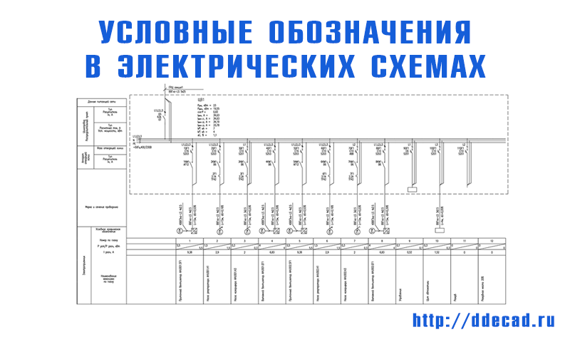
Example of a single-line diagram Wiring diagrams. E - IM, on which a manual drive is additionally installed. How radioelements are connected in a circuit So, it seems that we have decided on the task of this circuit.
Within groups, devices are divided by the number of poles, the presence of protection.
Sometimes the nominal data does not indicate, in this case the element parameters do not matter, you can select and install a link with a minimum value.The simplest example is an ordinary switch. To designate radio elements, single-letter and multi-letter codes are used. Let it be the R2 icon.
A bell on an electrical circuit according to UGO standards with a designated size UGO dimensions in electrical diagrams On the diagrams, the parameters of the elements included in the drawing are applied. Figure 6 When depicting an element or device on a diagram in a spaced way, it is allowed to put down the reference designation of each component part of the element or device, as in the combined method, but indicating for each part of the designations of the pins of the contacts. In the circuit diagrams of different industries, there are differences in the image of individual elements.


LETTER-NUMERIC DESIGNATIONS IN ELECTRICAL DIAGRAM
They are included in the developed drawings of the electrification of houses, apartments, and industries. If it is impossible to indicate the characteristics or parameters of the input and output circuits of the product, then it is recommended to indicate the name of the circuits or controlled quantities. Therefore, this article is mainly for them.
Complete information about the element is written, capacitance if it is a capacitor, nominal voltage, resistance for a resistor. The second type is more modern and actively applicable, especially in imported equipment. One-letter symbols of elements Letter codes corresponding to individual types of elements most widely used in electrical circuits are combined into groups designated by one symbol. Examples of symbols for electrical appliances and automation equipment in accordance with GOST
Basic basic images Electrical circuits lead to devices and installations that are equipped with contacts capable of breaking or connecting these circuits. All information is presented in blocks with captions - device names.
Conventional graphic designations of radio elements
Graphic and letter symbols in electrical circuits
Just as it is impossible to read a book without knowing the letters, so it is impossible to understand any electrical drawing without knowing the symbols.
In this article, we will consider the symbols in electrical diagrams: what happens, where to find the decoding, if it is not indicated in the project, how this or that element on the diagram should be correctly labeled and signed.
But let's start a little from afar. Every young specialist who comes into designing begins either by folding drawings, or by reading normative documentation, or draw “this” according to this example. In general, normative literature is studied in the course of work, design.
It is impossible to read all the normative literature related to your specialty or even a narrower specialization. Moreover, GOST, SNiP and other standards are periodically updated. And each designer has to keep track of changes and new requirements of regulatory documents, changes in the lines of electrical equipment manufacturers, and constantly maintain their qualifications at the proper level.
Remember Lewis Carroll in Alice in Wonderland?
“You have to run as fast just to stay in place, and to get somewhere, you have to run at least twice as fast!”
I'm not here to complain about "how hard the life of a designer" or to brag about "look what an interesting job we have."It's not about that now. Under such circumstances, designers learn from more experienced colleagues, many things just know how to do it right, but don't know why. They work on the principle of "It's the way it is here."
Sometimes, these are quite elementary things. You know how to do it right, but if they ask “Why is that?”, you won’t be able to answer right away, referring at least to the name of the regulatory document.
In this article, I decided to structure the information related to symbols, put everything on the shelves, collect everything in one place.
Types and meaning of lines
- Thin and thick solid lines - in the drawings depicts the lines of electrical, group communication, lines on the elements of the UGO.
- Dashed line - indicates the shielding of the wire or devices; denotes a mechanical connection (motor - gearbox).
- A thin dash-dotted line is intended to highlight groups of several components that make up parts of a device, or a control system.
- Dash-dotted with two dots - the line is disconnecting. Shows a breakdown of important elements. Indicates an object remote from the device that is associated with a mechanical or electrical system.

Network connecting lines are shown in full, but according to the standards, they are allowed to be cut off if they interfere with the normal understanding of the circuit. A break is indicated by arrows, next to it are the main parameters and characteristics of electrical circuits.
A bold dot on the lines indicates a connection, a soldering of wires.
Conclusion
At the same time, bundles and cables, stranded wires, electric cords are designated in accordance with the requirements of 5.
In the first case, control, control of elements and the power circuit itself are depicted; in a linear scheme, they are limited only to a chain with the image of the remaining elements on separate sheets.
Figure 8 5.
If it is impossible to indicate the characteristics or parameters of the input and output circuits of the product, then it is recommended to indicate the name of the circuits or controlled quantities. In this case, it is allowed to designate wires and cables as multi-core wires, do not assign electric cords. When executing the diagram on incomplete sheets, the following requirements must be met: - the numbering of the item designations of the elements must be continuous within the installation; - the list of elements should be general; - when re-imaging individual elements on other sheets of the diagram, the reference designations assigned to them on one of the first sheets of the diagram should be protected. With the positional sequential method, a design designation is a numeric or letter designation assigned to a given location of a position in a design.
Recommended: Device phase zero
In this case, the item designations of the elements are put down at one or both ends of the mechanical interconnection line. Table 5
Functional parts and connections between them are depicted in the form of conventional graphic symbols established in the relevant standards for conventional graphic symbols of these groups and elements.If all wires, bundles, cables, stranded wires, electrical cordsshown in the diagram belong to the same complex, room or functional circuit, then the alphanumeric designation is not affixed, and an appropriate explanation is placed on the diagram field. Graphic designations in electrical circuits Documentation, which specifies the rules and methods for graphic designation of circuit elements, is represented by three GOSTs: 2.
The wires of the bundle or cable strands of a stranded wire, electric cord are recorded in ascending order of the numbers assigned to the wires or wires; - when making connections with individual wires, wire harnesses and cables, stranded wires, electrical cords, in the connection table, first record individual wires without a header, and then with the corresponding headers, wire harnesses and cables, stranded wires, electrical cords. If necessary, the diagram indicates electrical circuits according to GOST 2.
Two-pole four-position switch 8. The table is connected by a leader line with the corresponding bundle, cable, stranded wire, electric cord, group of wires, see Figure 6 method, but with an indication for each part of the designations of the conclusions of the contacts.
How are radio components indicated on electronic circuits?