- 3 DEFINITIONS
- Versatility
- Measuring instruments
- Preparing for measurements
- 2.1.64
- Insulating protection of electrical equipment
- Natural and synthetic dielectrics
- General requirements
- 4.5 Lightning impulse test voltages
- Documentation of measurement results
- 2.1.58
- Classification of insulating materials
- Important "little things"
- Conclusions and useful video on the topic
3 DEFINITIONS
The following terms apply in this standard.
3.1 Voltage class of electrical equipment - rated phase-to-phase voltage of the electrical network for which the electrical equipment is intended.
Notes
1 Voltage class of the transformer (reactor) winding - according to GOST 16110.
2 Transformer voltage class - according to GOST 16110.
3 The voltage class of the grounding arc-suppression reactor is the voltage class of the winding of the power transformer or generator, in whose neutral the reactor is connected.
3.2 The highest operating voltage of electrical equipment - the highest frequency voltage of 50 Hz, an unlimited long-term application of which to the terminals of different phases (poles) of electrical equipment is permissible under the conditions of its insulation.
Note - The highest operating voltage of electrical equipment does not cover short-term (up to 20 s) voltage increases in emergency conditions and voltage increases with a frequency of 50 Hz (up to 8 hours) that are possible during operational switching specified in Appendix .
3.3 Electrical equipment with normal insulation - electrical equipment intended for use in electrical installations exposed to lightning overvoltages under normal lightning protection measures.
3.4 Electrical equipment with lightweight insulation - electrical equipment intended for use only in electrical installations not subject to lightning surges or in electrical installations in which lightning surges do not exceed the amplitude value of the test short-term (one-minute) alternating voltage.
3.5 Internal insulation - according to GOST 1516.2.
3.6 External insulation - according to GOST 1516.2.
3.7 Insulation level of electrical equipment (including windings, winding neutrals, etc.) - a set of normalized test voltages established in the standard for testing the internal and external insulation of this electrical equipment (windings, neutrals, etc.).
3.8 Rated test voltage - according to GOST 1516.2.
3.9 Electrical network with isolated neutral - a network whose neutral is not connected to earth, with the exception of signaling, measuring and protection devices that have a very high resistance, or a network whose neutral is connected to earth through an arcing reactor, the inductance of which is such that in the event of a single-phase earth fault, the reactor current in mainly compensates for the capacitive component of the earth fault current.
3.10 Electrical network with earthed neutral - a network whose neutral is connected to earth tightly or through a resistor or reactor, the resistance of which is small enough to significantly limit the transient fluctuations and provide the current value necessary for selective earth fault protection.
Note - The degree of earthing of the neutral of the network is characterized by the highest value of the earth fault factor for the schemes of this network, possible under operating conditions.
3.11 Earth fault ratio - the ratio of the voltage on the undamaged phase at the considered point of the three-phase electrical network (usually at the point of installation of electrical equipment) in the event of an earth fault of one or two other phases to the phase voltage of the operating frequency, which would be established at this point when the fault was eliminated.
Note - When determining the ground fault coefficient, the fault location and the state of the electrical network circuit are chosen such that give the highest coefficient value.
3.12 Type tests of insulation of electrical equipment - testing of electrical equipment of this type for compliance with its insulation to all the requirements established by the technical documentation, carried out after mastering the technology of its production or (partially or completely) after changes in the design, materials used or production technology that can reduce the dielectric strength of the insulation.
3.13 Periodic testing of insulation of electrical equipment - according to GOST 16504.
3.14 Acceptance tests of insulation of electrical equipment - according to GOST 16504.
3.15 Winding with full neutral insulation - a winding with a neutral insulation level equal to the insulation level of the linear end of the winding.
3.16 Winding with incomplete neutral insulation - a winding with a neutral insulation level lower than the insulation level of the linear end of the winding.
3.17 High (medium, low) voltage side of the transformer — according to GOST 16110.
3.18 Neutral side of transformer winding - a set of current-carrying parts connected to the neutral terminal and the part of the winding closest to the neutral end.
Versatility
Many manufacturers strive to make their power tools, especially drills, multifunctional. In addition to the main function, it can perform several additional ones. The market offers many models of drills that can drill, cut threads, work with screws, and in addition they can drill with impact, i.e.
Some vendors go even further - they offer a kit that includes a drill as the main power module and several attachments for it: a planer, an angle grinder, a circular saw, a jigsaw, etc. Such a set is usually made out in the form of a suitcase “For the master”. If the drill is also equipped with a hammer drill function, then at first glance such a set covers all requests.
You should not stop your choice on such sets. It must be remembered that each operation has its own peculiarity, it requires its own power, speed and duration of work. Working the tool with an overload or at the limit of its capabilities leads to its failure.
You can opt for a tool with additional functions only if their use is from 15 to 20% of the estimated scope of work.
Measuring instruments
Instruments for measuring insulation resistance are conventionally divided into two groups. These are: AC panel meters and small-sized devices (they are carried manually).The first samples are used in a set with mobile or stationary installations that have their own neutral. Structurally, they consist of relay and indicator parts and are capable of continuous operation in existing networks of 220 or 380 Volts.
Most often, measurements of the insulation resistance of electrical wiring are organized and carried out using mobile devices called megaohmmeters. Unlike a conventional ohmmeter, this device is intended for measurements of a special class, based on the assessment of the condition of the insulation when exposed to high voltage.
Known models of these devices are analog and digital. In the first of them, a mechanical principle is used to obtain the desired test voltage (as in a “dynamo”). Experts often call them "pointer", which is explained by the presence of a graduated scale and a measuring head with an arrow.
These devices are quite reliable and easy to use, but today they are obsolete. The main inconvenience of working with them is their considerable weight and large dimensions. They were replaced by modern digital meters, the circuit of which provides for a powerful generator assembled on a PWM controller and several field-effect transistors.
Such models, depending on the specific design, are able to work both from a mains adapter and from an autonomous power supply (one of the options is rechargeable batteries). Indications for measuring the insulation of power cables in these devices are displayed on the LCD display.The principle of their operation is based on the comparison of the tested parameter and the standard, after which the received data enters a special unit (analyzer) and is processed there.
Digital instruments are relatively light in weight and small in size, which is very convenient for field testing. Typical representatives of such devices are the popular Fluke 1507 meters (photo on the left). However, to work with an electronic circuit, a certain level of skill is needed to prepare the device and obtain the minimum measurement error during measurements. The same approach will be required when handling an imported digital product under the designation “1800 in”.
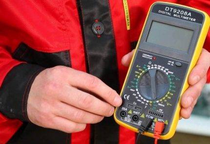
It is important to note that it does not make sense to check the insulation of cable products using conventional measuring instruments. Neither the most “advanced” multimeter, nor any other sample similar to it, is suitable for these purposes.
With their help, it will be possible to carry out only an approximate estimate of the parameter obtained with a large percentage of error.
Preparing for measurements
Preparation for insulation testing is reduced to the choice of a device that is suitable in terms of its characteristics for the stated purposes, as well as to the organization of a measurement scheme. The following devices are considered the most suitable for most cases:
- Megaohmmeters type M4100, having up to five modifications.
- Meters of the F 4100 series (models F4101, F4102, designed for limits from 100 Volts to one kilovolt).
- Devices ES-0202/1G (limits 100, 250, 500 Volts) and ES0202/2G (0.5, 1.0 and 2.5 kV).
- Fluke 1507 digital instrument (limits 50, 100, 250, 500, 1000 Volts).
Megaohmmeter M4100
Megaohmmeter-F-4100
Megaohmmeter-ES-02021G
Fluke 1507 Digital Meter
According to the PUE, before measuring the insulation resistance, it will be necessary to prepare a circuit for connecting a megohmmeter to the elements of the object being checked. To do this, the meter comes with a pair of flexible wires no more than 2 meters long. The intrinsic resistance of their insulation cannot be less than 100 Mohm.


We also note that for the convenience of checking the cable insulation with a megohmmeter, the working ends of the wires are marked, and special tips are put on them from the side of the device. On the opposite side, the measuring cables are equipped with crocodile clips with special probes and insulated handles.
2.1.64
In dry, dust-free rooms where there are no
vapors and gases that adversely affect the insulation and sheath of wires and
cables, it is allowed to connect pipes, ducts and flexible metal hoses
without seal.
Connection of pipes, ducts and flexible metal hoses
among themselves, as well as with boxes, electrical equipment cases, etc. must
be done:
in rooms that contain vapors or gases, negatively
affecting the insulation or sheaths of wires and cables, in external
installations and in places where it is possible for oil to get into pipes, boxes and hoses,
water or emulsion, - with a seal; boxes in these cases should be
with solid walls and with sealed solid covers or deaf, split
boxes - with seals in the places of the connector, and flexible metal sleeves -
tight;
in dusty rooms - with sealing of connections and branches
pipes, sleeves and boxes for dust protection.
Insulating protection of electrical equipment
Insulating materials provide protection for surrounding people and animals from electric shocks.There is only one condition: you need to choose the right consumable dielectric, its shape, thickness, operating voltage parameters (it can be different, like the design of the device).
In addition, the quality of insulators can be significantly affected by the production or domestic operating conditions of a complex electrical device. The quality of the insulation, thickness and degree of electrical resistance must correspond to the actual environmental influences and standard operating conditions.
To check the insulation properties, a test voltage is applied through the cable, and then, using a multimeter or tester, the insulation resistance of the electrical device is taken.
Information on how to check the voltage in an electrical outlet is contained in the following article, which we recommend that you read.
The composition of electrical insulation can include both a certain thickness of a dielectric layer and a structural form (case) made of a dielectric material. The dielectric covers the entire surface of the current-carrying elements of the equipment, or only those current-carrying elements that are isolated from other parts of the structure.
Natural and synthetic dielectrics
Insulating materials, otherwise, dielectrics, according to their origin are divided into natural (mica, wood, latex) and synthetic:
- film and tape insulators based on polymers;
- electrical insulating varnishes, enamels - solutions of film-forming substances, produced on the basis of organic solvents;
- insulating compounds that harden in a liquid state immediately after application to conductive elements.These substances do not contain solvents in their composition, according to their purpose they are divided into impregnating (treatment of windings of electrical appliances) and potting compounds, which are used to fill cable boxes and cavities of devices and electrical units for the purpose of sealing;
- sheet and roll insulating materials, which consist of unimpregnated fibers of both organic and inorganic origin. It can be paper, cardboard, fiber or fabric. They are made of wood, natural silk or cotton;
- varnished fabrics with insulating properties - special plastic materials on a fabric basis, impregnated with an electrically insulating composition, which, after hardening, forms an insulating film.
Synthetic dielectrics have electrical and physicochemical characteristics that are important for the reliable operation of devices and are specified by a specific technology for their production.
They are widely used in modern electrical engineering and electronics industry to market the following types of products:
- dielectric sheaths of cable and wire products;
- frames of electrical products, such as inductors, cases, racks, panels, etc.;
- elements of wiring fittings - distribution boxes, sockets, cartridges, cable connectors, switches, etc.
Electronic printed circuit boards are also produced, including panels used for wiring conductors.
General requirements
1.9.7. The choice of insulators or insulating structures made of glass and porcelain should be made according to the specific effective creepage distance depending on the SOC at the location of the electrical installation and its rated voltage.The choice of insulators or insulating structures made of glass and porcelain can also be made according to the discharge characteristics in a contaminated and wet state.
The choice of polymer insulators or structures, depending on the SZ and the rated voltage of the electrical installation, should be made according to the discharge characteristics in a polluted and wet state.
1.9.8. The determination of SZ should be made depending on the characteristics of pollution sources and the distance from them to the electrical installation (Tables 1.9.3 - 1.9.18). In cases where the use of Table. 1.9.3 - 1.9.18 for one reason or another is impossible, the determination of SZ should be made according to the SZ.
Near industrial complexes, as well as in areas with the imposition of pollution from large industrial enterprises, thermal power plants and sources of moisture with high electrical conductivity, the determination of SZ, as a rule, should be carried out according to the SZ.
1.9.9. The creepage distance L (cm) of insulators and insulating structures made of glass and porcelain shall be determined by the formula
L = λe U k,
- where λe is the specific effective creepage distance according to Table. 1.9.1, cm/kV;
- U is the highest operating phase-to-phase voltage, kV (according to GOST 721);
- k is the creepage distance utilization factor (1.9.44-1.9.53).
4.5 Lightning impulse test voltages
4.5.1 The test voltages of the full and cut lightning impulses should be, respectively, the standard full and cut lightning voltage impulses in accordance with GOST 1516.2 with the maximum values \u200b\u200bspecified in the tables - , , and paragraph of this standard.
4.5.2 When testing, the following should be applied:
a) for external insulation of electrical equipment and for internal insulation of current transformers and devices - pulses of positive and negative polarity;
b) for internal insulation of power transformers, voltage transformers, reactors and coupling capacitors - pulses of negative polarity.
4.5.3 Methods for testing insulation with lightning impulses and criteria for passing the test must comply with GOST 1516.2, sections 4 and 5, as well as standards for electrical equipment of certain types.
The following test methods shall be applied:
a) for internal insulation of electrical equipment (except gas-filled) - 3-shock method;
b) for external insulation of electrical equipment and internal insulation of gas-filled electrical equipment - 15-shock method.
For external insulation power transformers and between contacts the same pole of disconnectors and fuses with the cartridge removed, it is allowed to use the full discharge method instead of the 15-shock method; in this case, the withstand voltage with a probability of 90% must be not less than the corresponding test voltage.
4.5.4 Testing of internal and external insulation of power transformers, voltage transformers, current transformers, reactors, circuit breakers and coupling capacitors with lightning impulse voltages may be carried out simultaneously. In this case, the requirements for both internal and external insulation with respect to polarity, the number of pulses and their maximum value, which must be taken as the largest of the two values normalized for internal and external insulation, taking into account the correction for atmospheric conditions, must be satisfied. when tested.
4.5.5 Testing of insulators, disconnectors, short circuits, grounding switches, fuses, switchgear, PTS and shielded conductors with lightning impulse test voltages according to the method specified for external insulation is simultaneously a test of the electrical strength of their internal insulation.
Table 2 - Rated test voltages for electrical equipment of voltage classes from 3 to 35 kV with normal insulation
Voltages in kilovolts
Insulation level1)
Test voltage of internal and external insulation
lightning impulse
short-term (one-minute) variable
complete
cut
dry
in the rain 3)
Electrical equipment to earth and between phases (poles)2), between circuit-breaker contacts and switchgear with one break per pole
Between contacts of disconnectors, fuses and switchgear with two breaks per pole
Power and voltage transformers, shunt reactors to earth and between phases2)
Electrical equipment to earth (except power transformers, oil reactors) and between poles2), between circuit breaker contacts and switchgear with one break per pole
Power transformers, shunt and arcing reactors with respect to earth and other windings
Between contacts of disconnectors, fuses and switchgear with two breaks per pole
Electrical equipment to earth and between poles2), between switch contacts
Between fuse contacts
1
2
3
4
5
6
7
8
9
10
3
a
40
46
50
10
10
12
10
12
b
24
18
28
6
a
60
70
70
20/284)
20
23
20
23
b
32
25
37
10
a
75
85
90
28/384)
28
32
28
38
b
42
35
48
15
a
95
110
115
38/504)
38
45
38
45
b
55
45
63
20
a
125
145
150
50
50
60
50
60
b
65
55
75
24
a
150
165
175
60
60
70
60
70
b
75
65
90
27
a
170
190
200
65
65
85
65
75
b
80
70
95
35
a
190
220
220
80
80
95
80
95
b
95
85
120
1) Isolation level a - for electrical equipment with oil-paper and cast insulation, designed with the requirement to check the insulation for the absence of partial discharges, for the rest of the electrical equipment - it is established by agreement between the manufacturer and the consumer; isolation level b - for electrical equipment designed without the requirement to check the insulation for the absence of partial discharges.
2) For electrical equipment of three-phase (three-pole) design.
3) For electrical equipment of placement category 1 (except for power transformers and reactors).
4) The denominator indicates the values for post insulators of placement categories 2, 3 and 4; in the numerator - for the rest of the electrical equipment.
Documentation of measurement results
Based on the results of the work carried out, a separate document is prepared, in which all the necessary data are recorded.
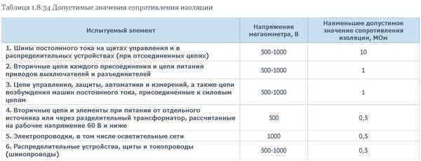
In household single-phase circuits, it will be enough to take three measurements. In the last lines of the completed protocol, there must be a phrase about the compliance of the results obtained with the requirements of the PUE.


In addition, they include the following information:
- Date and scope of surveys.
- Information about the composition of the working team (from the service personnel).
- Measuring instruments used for testing.
- The scheme of their connection, the ambient temperature, as well as the working conditions.
Upon completion of the recording of measurements, the log with the corresponding entries is removed to a safe place, where it is stored until the next test.Records of measurements stored in this way may be required at any time in order to serve as proof of the serviceability of a damaged product in emergency situations.
The finished protocol must be certified by the signature of the work foreman and the inspector appointed from the operational staff. To draw up measurement acts, it is allowed to use a regular notebook, but filling out a special form is considered a more legitimate and reliable way (its sample is given below).
Sample Insulation Resistance Measurement Protocol
A pre-prepared form of the protocol contains paragraphs that indicate:
- The procedure for carrying out measuring operations.
- The means of measurement used.
- Basic standards for the controlled parameter.
In addition, the form of electrical wiring measurement acts contains ready-made tables prepared for filling. In this form, the document is compiled on the computer only once, after which it is printed on the printer in several copies. This approach saves time on the preparation of documentation and gives the measurement acts a finished, official look.
2.1.58
In places where wires and cables pass through walls,
interfloor ceilings or their exit to the outside must be provided
the possibility of changing the wiring. To do this, the passage must be made in the pipe,
box, opening, etc. In order to prevent the penetration and accumulation of water and
spread of fire in places of passage through walls, ceilings or exits
outside, the gaps between the wires, cables and pipe (duct,
opening, etc.), as well as backup pipes (ducts, openings, etc.)
mass removed from non-combustible material. The seal must be capable of being replaced,
additional laying of new wires and cables and provide a limit
fire resistance of the opening is not less than the fire resistance of the wall (ceiling).
Classification of insulating materials
Electrical insulation in household appliances is divided into the following classes:
- 0;
- 0I;
- I;
- II;
- III.
Devices with insulation class "0" have a working insulating layer, but without the use of elements for grounding. In their design there is no clamp for connecting the protective conductor.
Instruments with insulation class "0I" have insulation + earthing element, but they contain a wire for connection to the power supply, which does not have a neutral conductor.
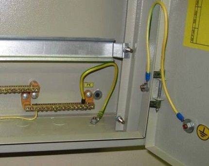
The insulation has a special marking. Grounding is indicated as a separate icon at the conductor connection point. This is done in order to equalize the potentials. The yellow-green conductor is connected to the contacts of the socket, chandelier, etc.
Appliances with insulation class "I" contain a 3-wire cord and a 3-prong plug. Wiring devices in this category must be installed with a connection to earth.
Electrical appliances with class II insulation, that is, double or reinforced, are often found in domestic use. Such insulation will reliably protect consumers from electric shock if the main insulation is damaged in the device.
Products equipped with strong double insulation are marked in power equipment with the symbol B, which means: "insulation in isolation." Devices containing such a sign must not be neutralized and grounded.
All modern electrical appliances with class III insulation can operate in power supply networks where there is a rated voltage not higher than 42 V.
Absolute safety when activating electrical equipment is provided by proximity switches, with the features of the device, the principle of operation and the types of which will be introduced by the article recommended by us.
Important "little things"
For some types of tools, two devices can be called absolutely necessary - a maximum speed controller and a soft starter. In the presence of a soft starter, it can smoothly gain momentum in proportion to the depth of pressing the start button.
One of the serious little things is the torque limit clutch, which protects the electric motor from unacceptable loads and increases its service life. The most common situation for creating an unacceptable load, for example for a drill, is the jamming of the drill at the time of drilling.
Another significant detail is the presence of reverse rotation. This property will be especially useful for drills. Without a reverse, it is impossible to cut a thread or turn out a screw. And if the drill has a reverse, then one more device is absolutely necessary - a rotation speed regulator.
If a powerful and heavy tool is purchased, then it is desirable to have an inrush current limiter in it. It picks up speed more smoothly, does not “twitch” in the hands and does not create an unnecessary load on the power grid.
Conclusions and useful video on the topic
Video contains instructions for use popular brand of megaohmmeter:
A small video review of insulating materials and methods for protecting current-carrying parts of electrical fittings:
Special types of insulation are used when equipping industrial switches, for example, air or oil type. They are not used in everyday life.If you had to deal with a violation of the insulation of switches in production, you should contact the specialists servicing electrical installations.
Please write comments in the box below. Share useful information on the topic of the article that will be useful to site visitors. Ask questions on controversial and unclear points, post photos.


