- Related videos
- Calculation of transformer power for lamps and connection diagram
- Rules for choosing step-down equipment
- What are transformers
- Toroidal electromagnetic device
- Pulse or electronic device
- Driver
- Device and principle of operation
- Helpful Hints
- Step-down transformer connection diagram
- How they function
- Purpose of ballast
- Safety
- Cathode heating
- Ensuring a high level of voltage
- Current limitation
- Process stabilization
Related videos
As you know, parallel connection of lamps is widely used in everyday life. However, a series circuit can also be applied and be useful.
Let's look at all the nuances of both schemes, mistakes that can be made during assembly and give examples of their practical implementation at home.
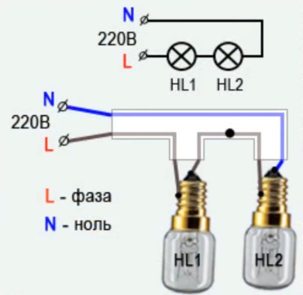
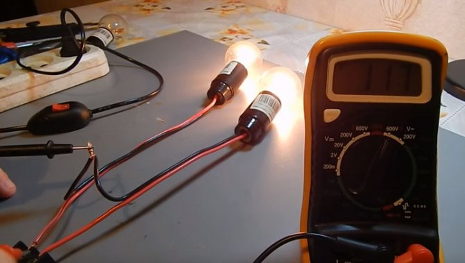
In the beginning, consider the simplest assembly of two incandescent bulbs connected in series.
- two lamps screwed into sockets
- two power wires coming out of the cartridges
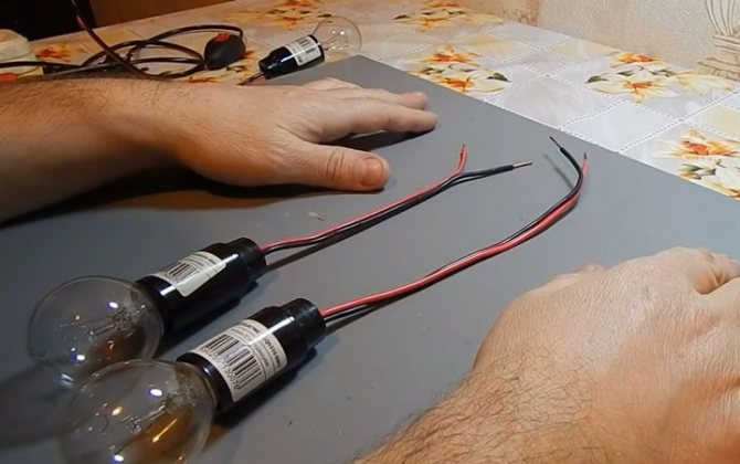
What do you need to connect them in series? There is nothing complicated here. Just take either end of the wire from each lamp and twist them together.

On the two remaining ends, you need to apply a voltage of 220 volts (phase and zero).
How would such a scheme work? When a phase is applied to the wire, it passes through the filament of one lamp, through the twist it enters the second light bulb. And then meets zero.
Why is such a simple connection practically not used in apartments and houses? This is explained by the fact that the lamps in this case will burn at less than full heat.

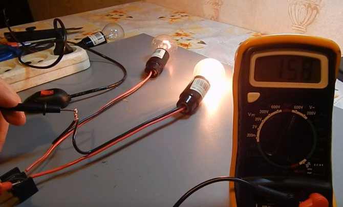
In this case, the stress will be distributed evenly across them. For example, if these are ordinary light bulbs of 100 watts with an operating voltage of 220 volts, then each of them will have plus or minus 110 volts.
Accordingly, they will shine less than half of their original power.
Roughly speaking, if you connect two 100W lamps in parallel, you will end up with a 200W lamp. And if the same circuit is assembled in series, then the total power of the lamp will be much less than the power of just one light bulb.
Based on the calculation formula, we get that two light bulbs shine with a power equal to everything: P=I*U=69.6W
If they differ, let's say one of them is 60W and the other is 40W, then the voltage on them will be distributed differently.
What does this give us in a practical sense in the implementation of these schemes?
A lamp will burn better and brighter, in which the filament has more resistance.
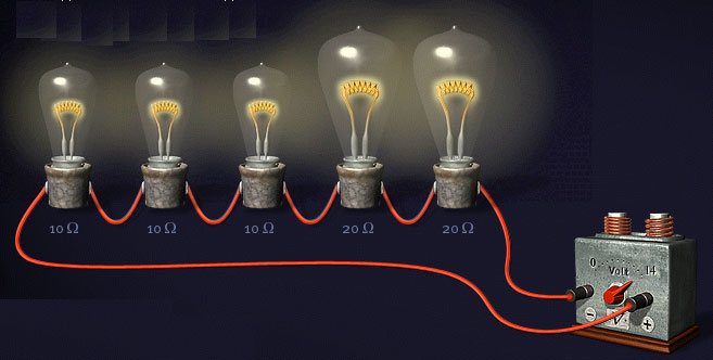
Take for example light bulbs that are radically different in power - 25W and 200W and connect in series.
Which of them will glow almost at full intensity? The one with P=25W.


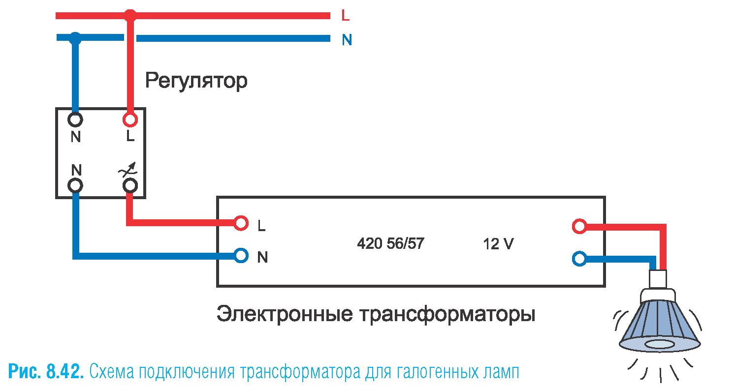
Calculation of transformer power for lamps and connection diagram
Various transformers are sold today, so there are certain rules for selecting the required power. Do not take a transformer too powerful. It will run almost idle.Lack of power will lead to overheating and further failure of the device.
You can calculate the power of the transformer yourself. The problem is rather mathematical and within the power of every novice electrician. For example, you need to install 8 spot halogens with a voltage of 12 V and a power of 20 watts. The total power in this case will be 160 watts. We take with a margin of 10% approximately and acquire a power of 200 watts.
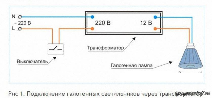
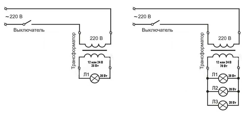
Scheme No. 1 looks something like this: there is a single-gang switch on line 220, while the orange and blue wires are connected to the transformer input (primary terminals).
On the 12 volt line, all lamps are connected to a transformer (to the secondary terminals). The connecting copper wires must necessarily have the same cross section, otherwise the brightness of the bulbs will be different.
Another condition: the wire connecting the transformer to the halogen lamps must be at least 1.5 meters long, preferably 3. If you make it too short, it will start to heat up and the brightness of the bulbs will decrease.
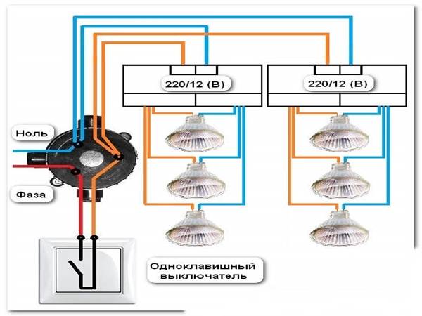
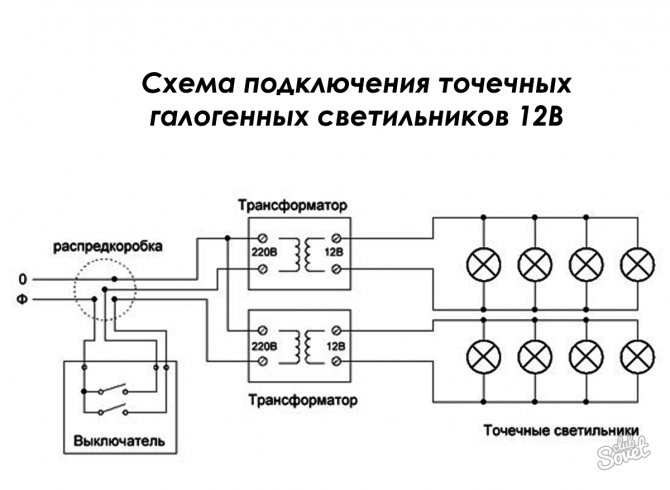
Scheme No. 2 - for connecting halogen lamps. Here you can do it differently. Break, for example, six lamps into two parts. For each, install a step-down transformer. The correctness of this choice is due to the fact that if one of the power supplies breaks down, the second part of the fixtures will still continue to work. The power of one group is 105 watts. With a small safety factor, we get that you need to purchase two 150-watt transformers.
Advice! Power each step-down transformer with your own wires and connect them in the junction box. Leave the connections free.
Rules for choosing step-down equipment
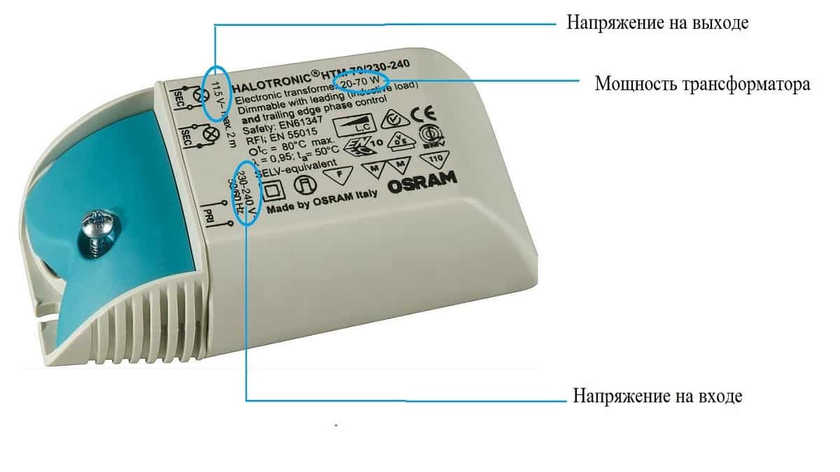
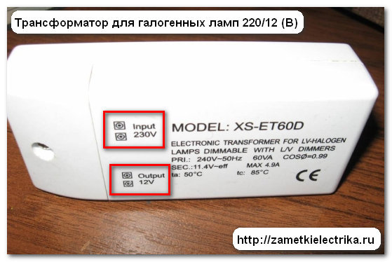
Choosing a transformer for halogen light sources type, there are many factors to consider. It’s worth starting with two most important characteristics: the output voltage of the device and its rated power. The first must strictly correspond to the operating voltage of the lamps connected to the device. The second one determines the total power of the light sources with which the transformer will work.
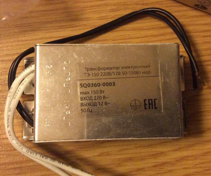
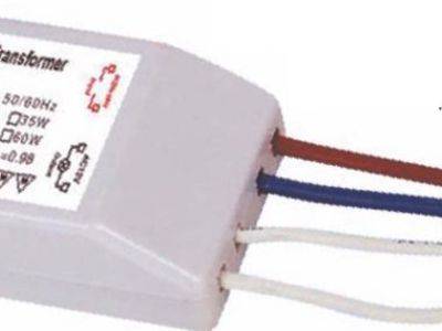
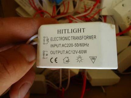
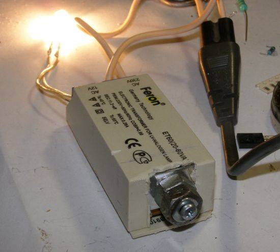
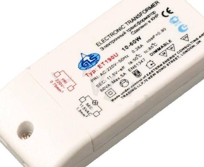
There is always a marking on the transformer case, having studied which you can get complete information about the device
To accurately determine the required rated power, it is desirable to make a simple calculation. To do this, you need to add up the power of all light sources that will be connected to the step-down device. To the value obtained, add 20% of the "margin" necessary for the correct operation of the device.
Let's illustrate with a specific example. To illuminate the living room, it is planned to install three groups of halogen lamps: seven in each. These are point devices with a voltage of 12 V and a power of 30 watts. You will need three transformers for each group. Let's pick the right one. Let's start with the calculation of the rated power.
We calculate and get that the total power of the group is 210 watts. Taking into account the required margin, we get 241 watts. Thus, for each group, a transformer is required, the output voltage of which is 12 V, the rated power of the device is 240 W.
Both electromagnetic and pulse devices are suitable for these characteristics.
Stopping your choice on the latter, you need to pay special attention to the rated power. It must be presented as two digits.
The first indicates the minimum operating power. You need to know that the total power of the lamps must be greater than this value, otherwise the device will not work.
And a small note from experts regarding the choice of power. They warn that the power of the transformer, which is indicated in the technical documentation, is the maximum. That is, in the normal state, it will give out somewhere 25-30% less. Therefore, the so-called "reserve" of power is necessary. Because if you force the device to work at its limit, it will not last long.
For long-term operation of halogen lamps, it is very important to correctly select the power of the step-down transformer. At the same time, it must have some “margin” so that the device does not work at the limit of its capabilities. Another important nuance concerns the dimensions of the selected transformer and its location.
The more powerful the device, the more massive it is. This is especially true for electromagnetic units. It is advisable to immediately find a suitable place for its installation. If there are several fixtures, users often prefer to divide them into groups and install a separate transformer for each
Another important nuance concerns the size of the selected transformer and its location. The more powerful the device, the more massive it is. This is especially true for electromagnetic units. It is advisable to immediately find a suitable place for its installation. If there are several fixtures, users often prefer to divide them into groups and install a separate transformer for each.


This is explained very simply. Firstly, if the step-down device fails, the rest of the lighting groups will work normally.Secondly, each of the transformers installed in such groups will have less power than the total one that would need to be supplied for all lamps. Therefore, its cost will be noticeably lower.
What are transformers
Transformers are devices of electromagnetic or electronic type. They differ somewhat in the principle of operation and some other characteristics. Electromagnetic options change the parameters of the standard mains voltage to characteristics suitable for the operation of halogens, electronic devices, in addition to the specified work, also perform current conversion.
Toroidal electromagnetic device
The simplest toroidal transformer is assembled from two windings and a core. The latter is also called a magnetic circuit. It is made of a ferromagnetic material, usually steel. The windings are placed on the rod. The primary is connected to the energy source, the secondary, respectively, to the consumer. There is no electrical connection between the secondary and primary windings.
Despite the low cost and reliability in operation, the toroidal electromagnetic transformer is rarely used today when connecting halogen lamps.
Thus, the power between them is transmitted only electromagnetically. To increase the inductive coupling between the windings, a magnetic circuit is used. When an alternating current is applied to the terminal connected to the first winding, it forms an alternating type magnetic flux inside the core. The latter interlocks with both windings and induces an electromotive force or EMF in them.
Under its influence, an alternating current is created in the secondary winding with a voltage different from what was in the primary.Depending on the number of turns, the type of transformer is set, which can be step-up or step-down, and the transformation ratio. For halogen lamps, only step-down devices are always used.
The advantages of winding devices are:
- High reliability in work.
- Ease of connection.
- Low cost.
However, toroidal transformers can be found in modern circuits with halogen lamps rare enough. This is due to the fact that, due to the design features, such devices have quite impressive dimensions and weight. Therefore, it is difficult to disguise them when arranging furniture or ceiling lighting, for example.
Perhaps the main drawback of toroidal electromagnetic transformers is their massiveness and significant dimensions. They are extremely difficult to disguise if hidden installation is necessary.
Also, the disadvantages of devices of this type include heating during operation and sensitivity to possible voltage drops in the network, which negatively affects the life of halogens. In addition, winding transformers can hum during operation, this is not always acceptable. Therefore, the devices are mostly used in non-residential premises or in industrial buildings.
Pulse or electronic device
The transformer consists of a magnetic core or core and two windings. Depending on the shape of the core and the way the windings are placed on it, four types of such devices are distinguished: rod, toroidal, armored and armored rod. The number of turns of the secondary and primary windings can also be different. By varying their ratios, step-down and step-up devices are obtained.
In the design of a pulse transformer, there are not only windings with a core, but also an electronic filling. Thanks to this, it is possible to integrate protection systems against overheating, soft start and other
The principle of operation of a pulse type transformer is somewhat different. Short unipolar pulses are applied to the primary winding, due to which the core is constantly in a state of magnetization. The pulses on the primary winding are characterized as short-term square wave signals. They generate inductance with the same characteristic drops.
They, in turn, create impulses on the secondary coil. This feature gives electronic transformers a number of advantages:
- Light weight and compact.
- High level of efficiency.
- Possibility to build additional protection.
- Extended operating voltage range.
- No heat or noise during operation.
- The ability to adjust the output voltage.
Among the shortcomings, it is worth noting the regulated minimum load and the rather high price. The latter is associated with certain difficulties in the manufacturing process of such devices.
Driver
The use of a driver instead of a transformer unit is due to the peculiarities of the operation of the LED, as an integral element of modern lighting equipment. The thing is that any LED is a non-linear load, the electrical parameters of which change depending on the operating conditions.
 Rice. 3. Volt-ampere characteristic of the LED
As you can see, even with slight voltage fluctuations, a significant change in current strength will occur. Especially clearly such differences are felt by powerful LEDs.Also, there is a temperature dependence in the work, therefore, when the element is heated, the voltage drop decreases, and the current increases. This mode of operation has an extremely negative effect on the operation of the LED, which is why it fails faster. You cannot connect it directly from the mains rectifier, for which drivers are used.
The peculiarity of the LED driver is that it produces the same current from the output filter, regardless of the size of the voltage applied to the input. Structurally modern drivers for connecting LEDs can be performed both on transistors and microchip based. The second option is gaining more and more popularity due to the better characteristics of the driver, easier control of the operation parameters.
The following is an example of a driver operation scheme:
 Rice. 4. Driver circuit example


Here, a variable value is supplied to the input of the mains voltage rectifier VDS1, then the rectified voltage in the driver is transmitted through the smoothing capacitor C1 and the half-arm R1 - R2 to the BP9022 chip. The latter generates a series of PWM pulses and transmits it through a transformer to the output rectifier D2 and the output filter R3 - C3, used to stabilize the output parameters. Due to the introduction of additional resistors in the power circuit of the microcircuit, such a driver can adjust the output power and control the intensity of the light flux.
Device and principle of operation
Electronic and electromagnetic models of transformers differ both in their design and in the principle of operation, therefore they should be considered separately:
The transformer is electromagnetic.
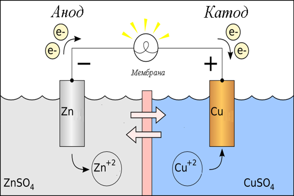
As already mentioned above, the basis of this design is a toroidal core made of electrical steel, on which the primary and secondary windings are wound. There is no electrical contact between the windings, the connection between them is carried out by means of an electromagnetic field, the action of which is due to the phenomenon of electromagnetic induction. The diagram of the step-down electromagnetic transformer is shown in the figure below, where:
- the primary winding is connected to a 220 volt network (U1 in the diagram) and an electric current "i1" flows in it;
- when voltage is applied to the primary winding, an electromotive force (EMF) is formed in the core;
- EMF creates a potential difference on the secondary winding (U2 in the diagram) and, as a result, the presence of an electric current "i2" with a connected load (Zn in the diagram).
Electronic and circuit diagram of a toroidal transformer
The specified voltage value on the secondary winding is created by winding a certain number of turns of wire on the core of the device.
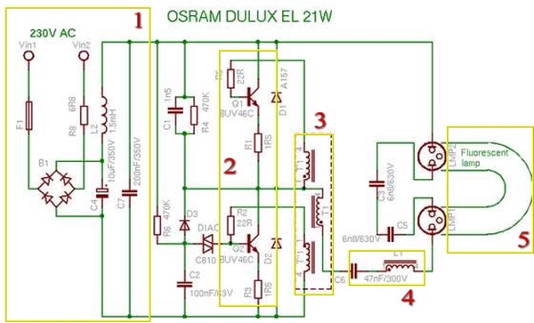
The transformer is electronic.
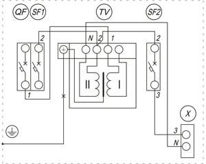
The design of such models provides for the presence of electronic components, through which voltage conversion is carried out. In the diagram below, the voltage of the electrical network is applied to the input of the device (INPUT), after which it is converted into a constant by means of a diode bridge, on which the electronic components of the device operate.
The control transformer is wound on a ferrite ring (windings I, II and III), and it is its windings that control the operation of the transistors, and also provide communication with the output transformer that outputs the converted voltage to the output of the device (OUTPUT).In addition, the circuit contains capacitors that provide the required shape of the output voltage signal.
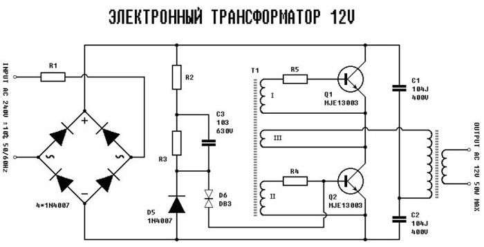
Schematic diagram of an electronic transformer 220 to 12 Volts
The above electronic transformer circuit can be used to connect halogen lamps and other light sources operating at a voltage of 12 volts.
Helpful Hints
When connecting halogen lamps, you must follow the useful tips:
- Often fixtures are produced with non-standard wire markings. This is taken into account when connecting the phase and zero. Wrong connection will cause problems.
- When installing fixtures through a dimmer, special LED lamps should also be used.
- Wiring must be grounded.
- The output wire should not be longer than 2 meters, otherwise there will be a loss of current and the lamps will shine much dimmer.
- The transformer should not overheat, for this they are installed no closer than 20 centimeters from the lighting device itself.
- When the transformer is located in a small cavity, the load must be reduced to 75 percent.
- Installation of spotlights is done after complete surface finishing.
- Installation of halogen spotlights can be done independently, following the installation rules.
- If the lamp is square, then first a circle is cut out with a crown, and then the corners are cut (for plastic, plasterboard suspended ceilings).
- When installing in the bathroom, you must use a 12 V transformer. Such a voltage will not harm a person.
We advise you to watch the video instruction:
Step-down transformer connection diagram
How to connect a 220 to 12 volt transformer is of interest to many. Everything is done simply.Suggests the algorithm of actions marking at the connection points. The output terminals on the connection panel with the contact wires of the consumer device are marked in Latin letters. The terminals to which the neutral wire is connected are marked with the symbols N or 0. The power phase is designated L or 220. The output terminals are marked with the numbers 12 or 110. It remains not to confuse the terminals and answer the question of how to connect a step-down transformer 220 with practical actions.
The factory marking of the terminals ensures safe connection by a person who is not familiar with such actions. Imported transformers pass domestic certification control and do not pose a danger during operation. Connect the product to 12 volts according to the principle described above.

Now it’s clear how a factory-made step-down transformer is connected. It is more difficult to decide on a homemade device. Difficulties arise when, during the installation of the device, they forget to mark the terminals


To make the connection without error, it is important to learn how to visually determine the thickness of the wires. The primary coil is made of wire of a smaller section than the end-action winding
The connection scheme is simple.
It is necessary to learn the rule according to which it is possible to obtain a step-up electrical voltage, the device is connected in the reverse order (mirror version).
The principle of operation of a step-down transformer is easy to understand.It has been empirically and theoretically established that the coupling at the level of electrons in both coils should be estimated as the difference between the magnetic flux effect that creates contact with both coils and the electron flux that occurs in a winding with a smaller number of turns. By connecting the terminal coil, it is found that a current appears in the circuit. That is, they receive electricity.
And here there is an electrical collision. It is calculated that the energy supplied from the generator to the primary coil is equal to the energy directed into the created circuit. And this happens when there is no metal, galvanic contact between the windings. Energy is transferred by creating a powerful magnetic flux with variable characteristics.
In electrical engineering there is a term "dissipation". The magnetic flux along the route loses power. And that's bad. The design feature of the transformer device corrects the situation. The created designs of metal magnetic paths do not allow the dispersion of the magnetic flux along the circuit. As a result, the magnetic fluxes of the first coil are equal to the values of the second or almost equal.
How they function
Structurally, all lighting elements with a filament are the same and consist of a base, a filament body with a filament and a glass bulb. But halogen lamps differ in the content of iodine or bromine.
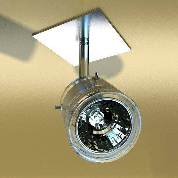
Their functioning is as follows. The tungsten atoms that make up the filament are released and react with halogens - iodine or bromine (this prevents them from depositing on the inside of the flask walls), creating a stream of light. Filling with gas significantly extends the life of the source.
Then the reverse development of the process occurs - high temperature causes new compounds to break down into their constituent parts. Tungsten is released on or near the surface of the filament.
This principle of operation makes the luminous flux more intense and lengthens the life of the halogen lamp (12 volts or higher - it doesn’t matter, the statement is true for all types)
Purpose of ballast
Mandatory electrical characteristics of a daylight luminaire:
- Consumed current.
- starting voltage.
- Current frequency.
- Current crest factor.
- Illumination level.
The inductor provides a high initial voltage to initiate the glow discharge and then quickly limits the current to safely maintain the desired voltage level.
The main functions of the ballast transformer are discussed below.
Safety
The ballast regulates the AC power for the electrodes. When alternating current passes through the inductor, the voltage rises. At the same time, the current strength is limited, which prevents a short circuit, which leads to the destruction of the fluorescent lamp.
Cathode heating
For the lamp to work, a high voltage surge is necessary: it is then that the gap between the electrodes breaks down, and the arc lights up. The colder the lamp, the higher the required voltage. The voltage "pushes" the current through the argon. But the gas has a resistance, which is higher, the colder the gas. Therefore, it is required to create a higher voltage at the lowest possible temperatures.
To do this, you need to implement one of two schemes:
- using a starting switch (starter) containing a small neon or argon lamp with a power of 1 W.It heats the bimetallic strip in the starter and facilitates the initiation of a gas discharge;
- tungsten electrodes through which current passes. In this case, the electrodes heat up and ionize the gas in the tube.
Ensuring a high level of voltage
When the circuit is broken, the magnetic field is interrupted, high voltage impulse sent through the lamp, and a discharge is excited. The following high voltage generation schemes are used:
- Preheating. In this case, the electrodes are heated until the discharge is initiated. The start switch closes, allowing current to flow through each electrode. The starter switch cools rapidly, opening the switch and starting the supply voltage on the arc tube, resulting in a discharge. During operation, no auxiliary power is supplied to the electrodes.
- Quick start. The electrodes heat up constantly, so the ballast transformer includes two special secondary windings that provide a low voltage on the electrodes.
- Instant start. The electrodes do not heat up before starting work. For instant starters, the transformer provides a relatively high starting voltage. As a result, the discharge is easily excited between the "cold" electrodes.
Current limitation
The need for this arises when a load (for example, an arc discharge) is accompanied by a voltage drop at the terminals when the current increases.
Process stabilization
There are two requirements for fluorescent lamps:
- to start the light source, a high voltage jump is needed to create an arc in mercury vapor;
- once the lamp is started, the gas offers decreasing resistance.
These requirements vary depending on the power of the source.


