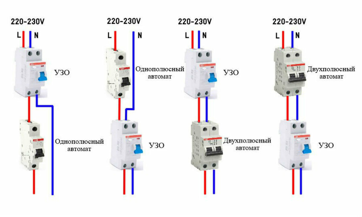
- Protection options for a single-phase network
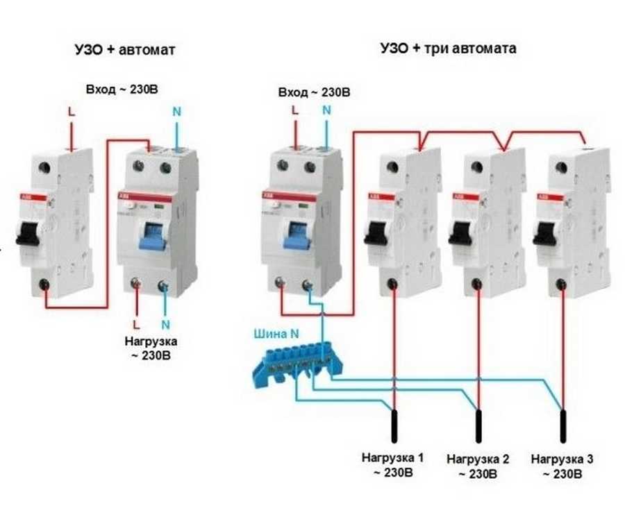
- Option #1 - common RCD for 1-phase network.
- Option #2 - common RCD for 1-phase network + meter.
- Option #3 - common RCD for 1-phase network + group RCD.
- Option #4 - 1-phase network + group RCDs.
- Financial aspect
- RCD connection diagram
- Installation and connection of elements
- The difference between an electromechanical RCD with 2 and 4 windings from an electronic one
- Step by step wiring diagram
- Types of RCD
- Electromechanical RCDs
- Electronic RCDs
- Step-by-step instructions for implementing protection
- Wiring diagrams
- Conclusions and useful video on the topic
Protection options for a single-phase network
Manufacturers of powerful household appliances mention the need to install a set of protective devices. Often, the accompanying documentation for a washing machine, electric stove, dishwasher or boiler indicates which devices need to be additionally installed in the network.
However, more and more often several devices are used - for separate circuits or groups. In this case, the device in conjunction with the machine (s) is mounted in a panel and connected to a certain line
Considering the number of different circuits serving sockets, switches, equipment that loads the network to the maximum, we can say that there are an infinite number of RCD connection schemes.In domestic conditions, you can even install a socket with a built-in RCD.
Next, consider the popular connection options, which are the main ones.
Option #1 - common RCD for 1-phase network.
The place of the RCD is at the entrance of the power line to the apartment (house). It is installed between a common 2-pole machine and a set of machines for servicing various power lines - lighting and socket circuits, separate branches for household appliances, etc.
If a leakage current occurs on any of the outgoing electrical circuits, the protective device will immediately turn off all lines. This, of course, is its minus, since it will not be possible to determine exactly where the malfunction is.
Suppose that a current leakage has occurred due to the contact of a phase wire with a metal device connected to the network. The RCD trips, the voltage in the system disappears, and it will be quite difficult to find the cause of the shutdown.
The positive side concerns savings: one device costs less, and it takes up less space in the electrical panel.
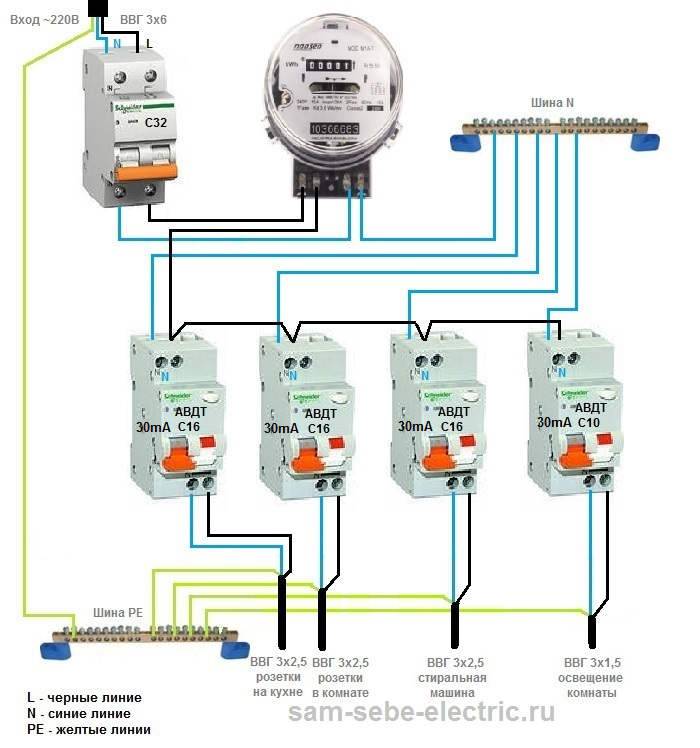
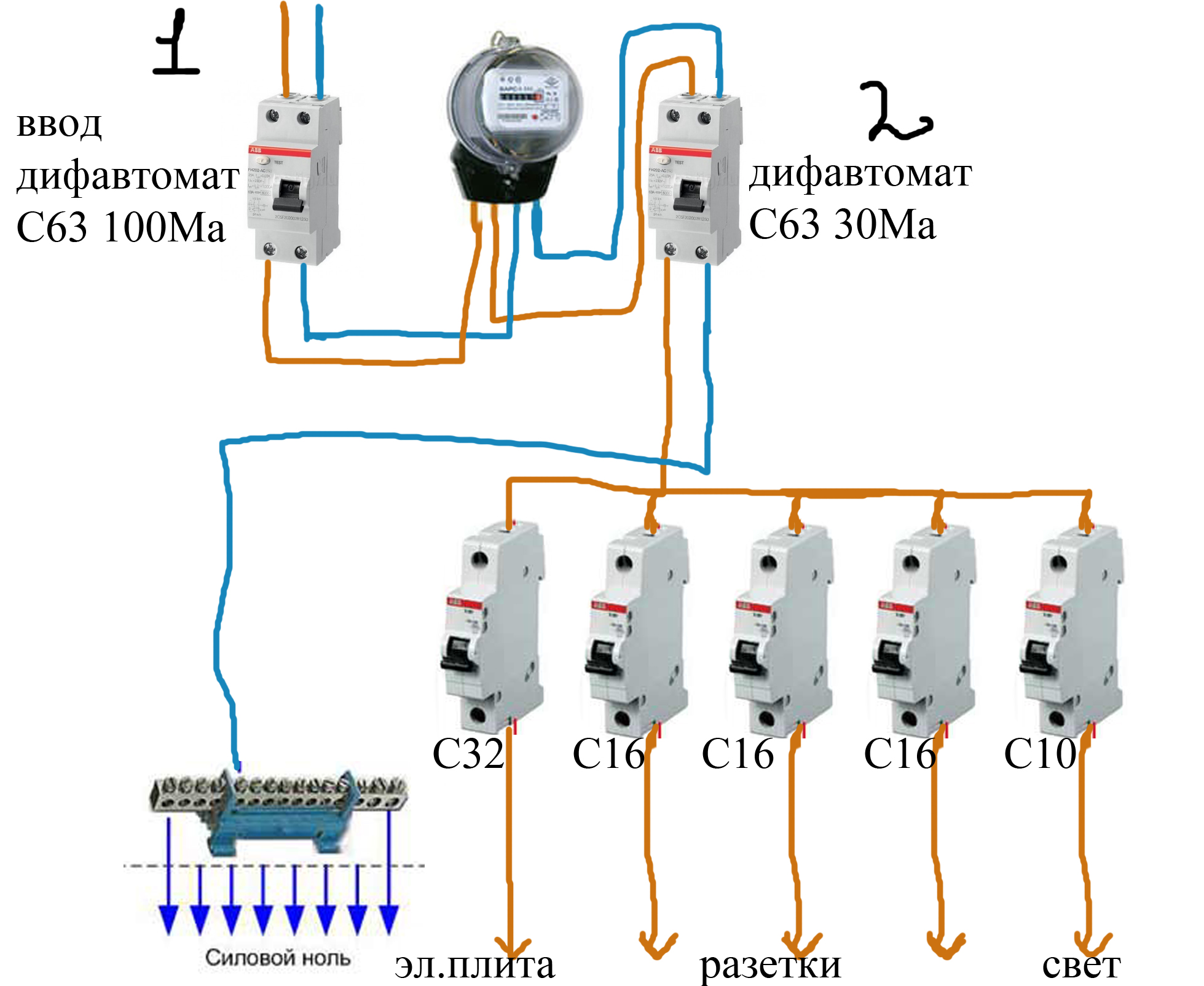
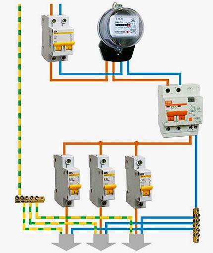
Option #2 - common RCD for 1-phase network + meter.
A distinctive feature of the scheme is the presence of an electricity meter, the installation of which is mandatory.
Current leakage protection is also connected to the machines, but a meter is connected to it on the incoming line.
If it is necessary to cut off the power supply to an apartment or house, they turn off the general machine, and not the RCD, although they are installed side by side and serve the same network
The advantages of this arrangement are the same as those of the previous solution - saving space on the electrical panel and money. The disadvantage is the difficulty of detecting the place of current leakage.
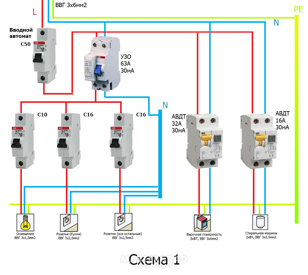
Option #3 - common RCD for 1-phase network + group RCD.
The scheme is one of the more complicated varieties of the previous version.
Thanks to the installation of additional devices for each working circuit, protection against leakage currents becomes double. From a security point of view, this is a great option.
Suppose an emergency current leakage occurred, and the connected RCD of the lighting circuit for some reason did not work. Then the common device reacts and disconnects all lines
So that both devices (private and common) do not immediately work, it is necessary to observe selectivity, that is, when installing, take into account both the response time and the current characteristics of the devices.
The positive side of the scheme is that in an emergency one circuit will turn off. It is extremely rare that the entire network goes down.
This can happen if the RCD installed on a particular line:
- defective;
- out of order;
- does not match the load.
To avoid such situations, we recommend that you familiarize yourself with the methods for checking the RCD for performance.
Cons - the workload of the electrical panel with a lot of the same type of devices and additional expenses.
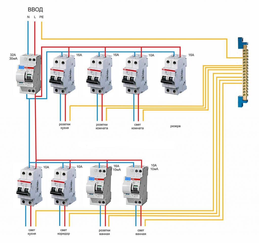
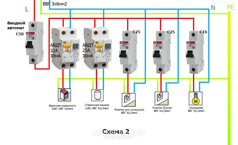
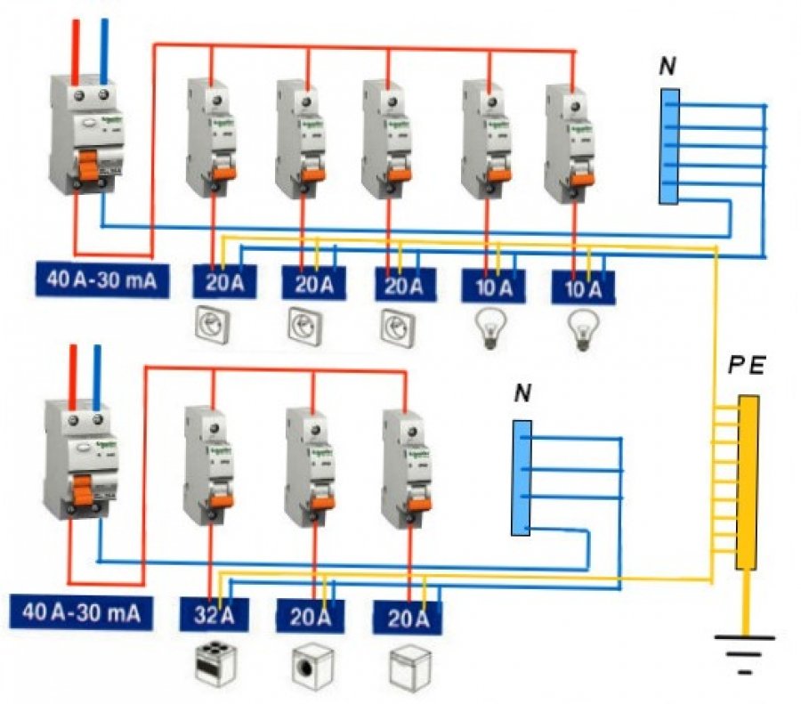
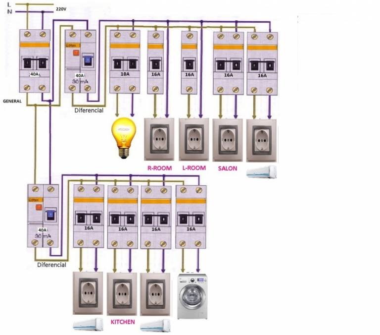
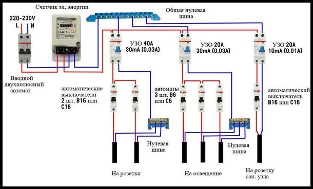
Option #4 - 1-phase network + group RCDs.
Practice has shown that the circuit without installing a common RCD also functions well.
Of course, there is no insurance against the failure of one protection, but this can be easily fixed by purchasing a more expensive device from a manufacturer you can trust.
The scheme resembles a variant with general protection, but without installing an RCD for each individual group. It has an important positive point - it is easier to determine the source of the leak here
From the point of view of economy, the wiring of several devices loses - one common one would cost much less.
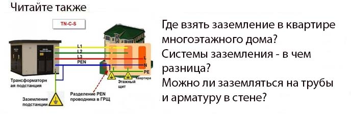
If the electrical network in your apartment is not grounded, we recommend that you familiarize yourself with the RCD connection diagrams without grounding.
Financial aspect
And most importantly, how RCDs and RCBOs differ in cases of private use at home - the cost. It demonstrates well what most users will prefer, especially when viewed from the device in terms of reliability, which is the same for famous manufacturers.
And here's why price will eventually become the main consideration when choosing:
- the complexity of the connection will eventually cease to bother, as experience will be gained and the installation will no longer be something difficult and unknown;
- finding the reasons for the shutdown will also not become a problem over time, when you have to go through about five unforeseen situations;
- reliability and workmanship will become the main aspect, because it will speak about long-term operation more than anything else.
And now, when we come to the cost, taking into account all the connections and the purchase of a shield, where there will be enough space for everything, the difference in price will not even exceed 4,000 rubles. This is not such a large amount that is worth saving in matters of electrics, since much more can be lost due to improper power supply.
The choice between an RCD and a difavtomat is really worth paying attention to, because the life of not only household appliances, but also a person depends on electricity. Negligent attitude and savings can lead to death or a fire, which is not worth either one or the other.
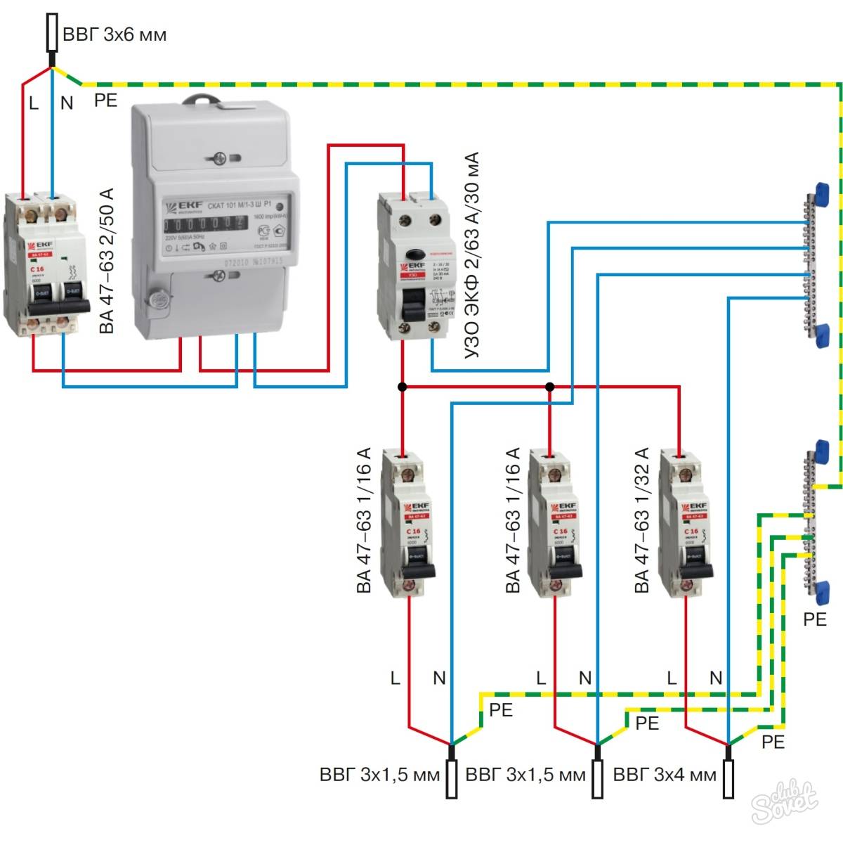
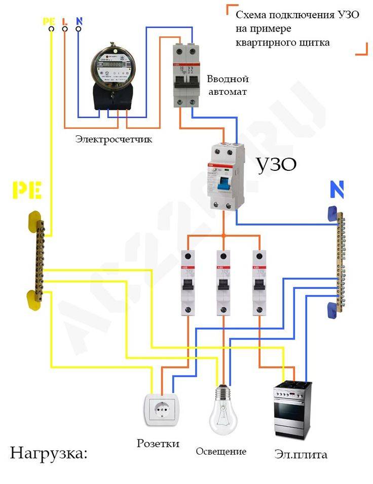
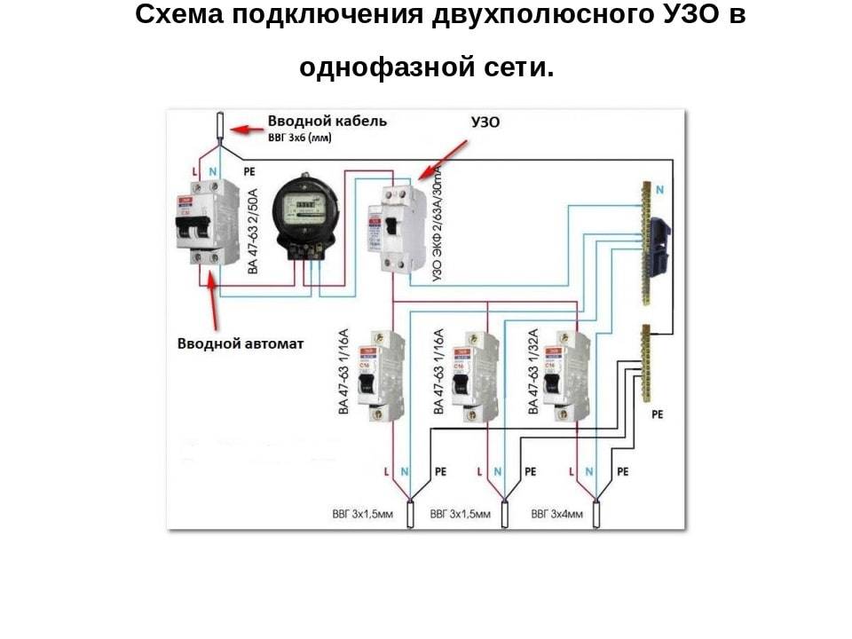
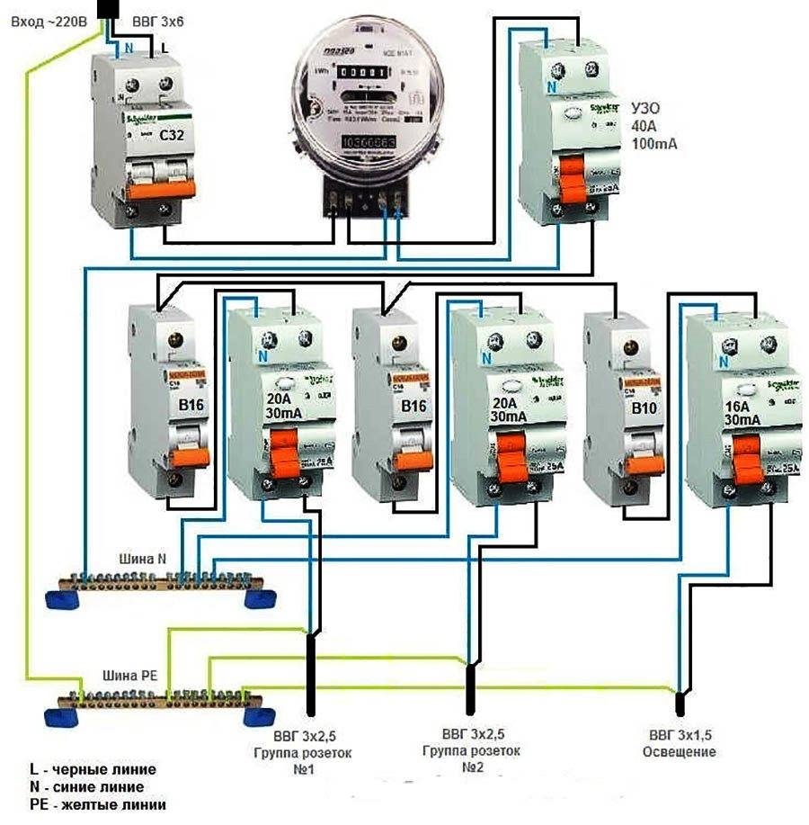
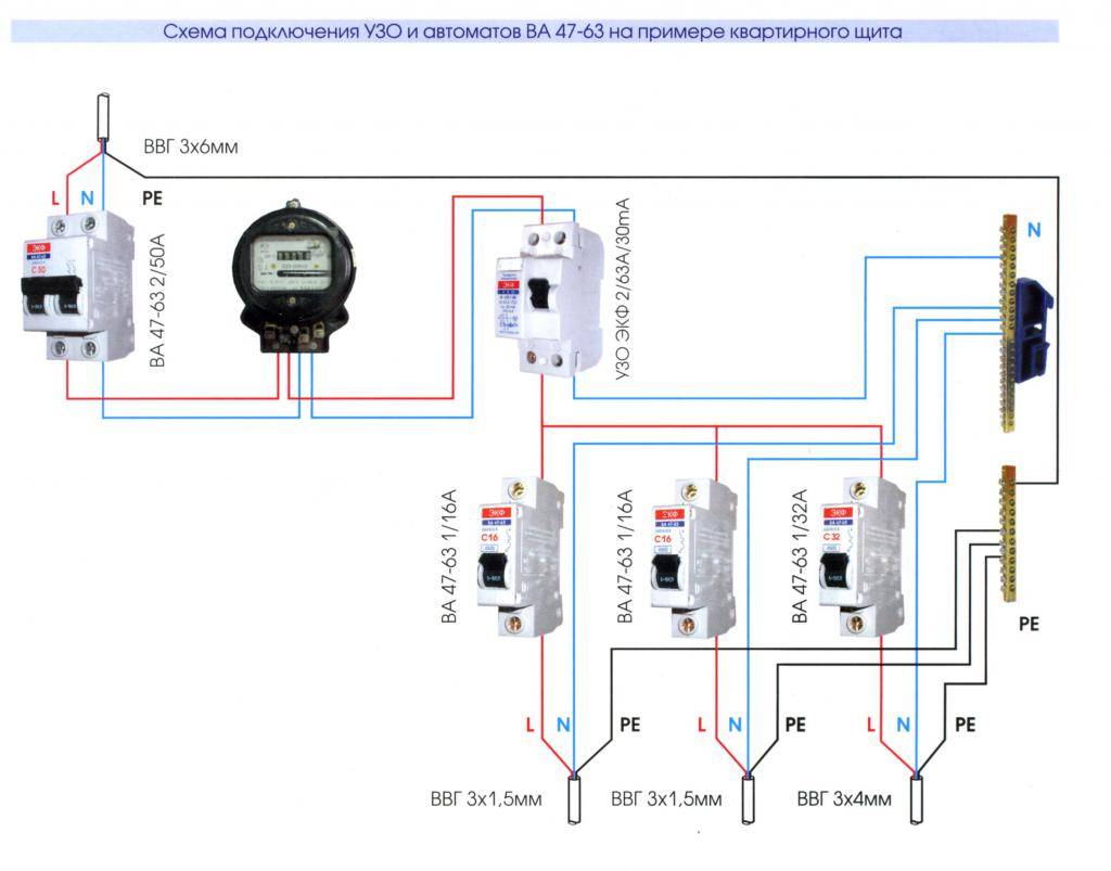
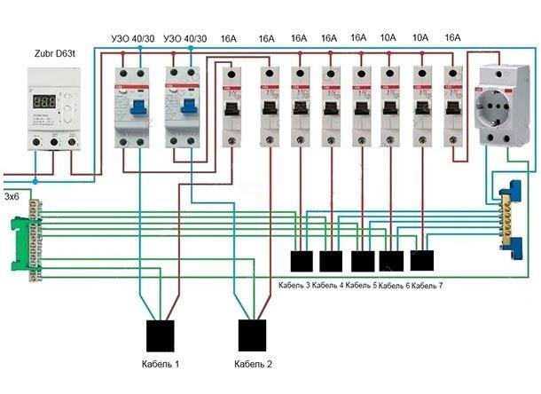
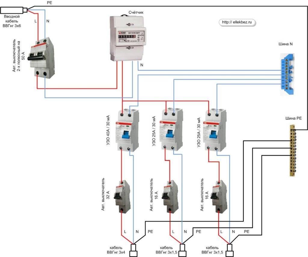
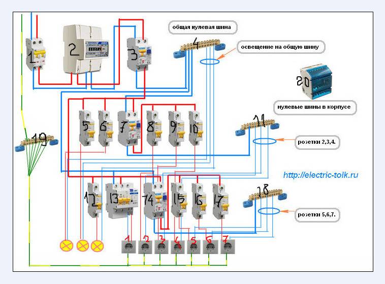
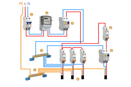
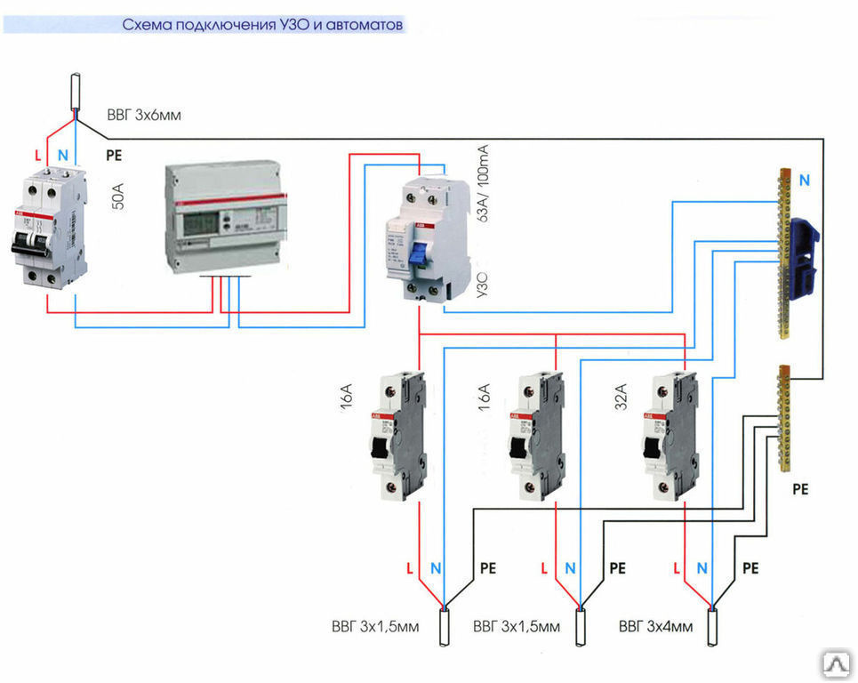
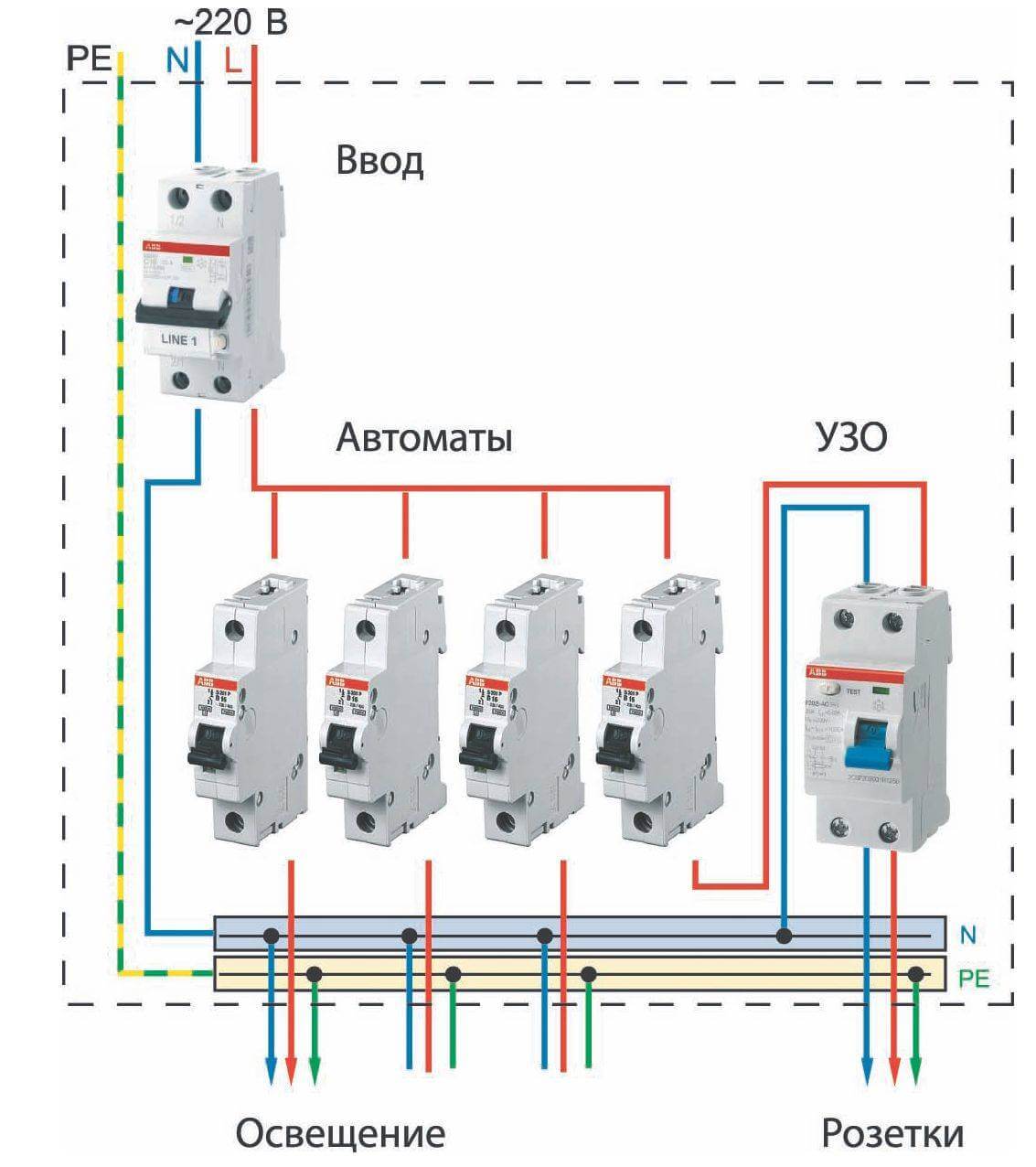
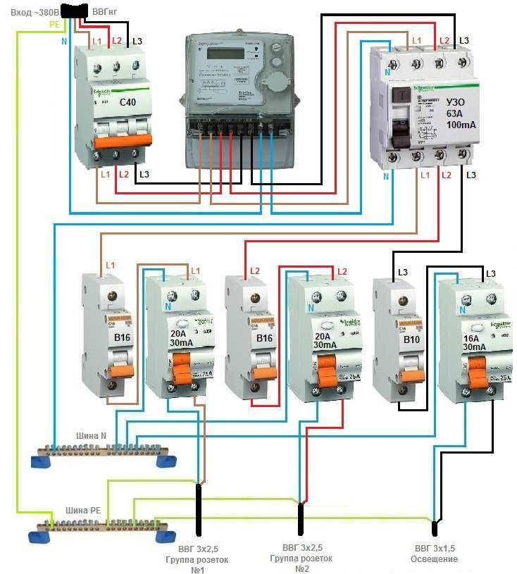
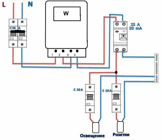
RCD connection diagram
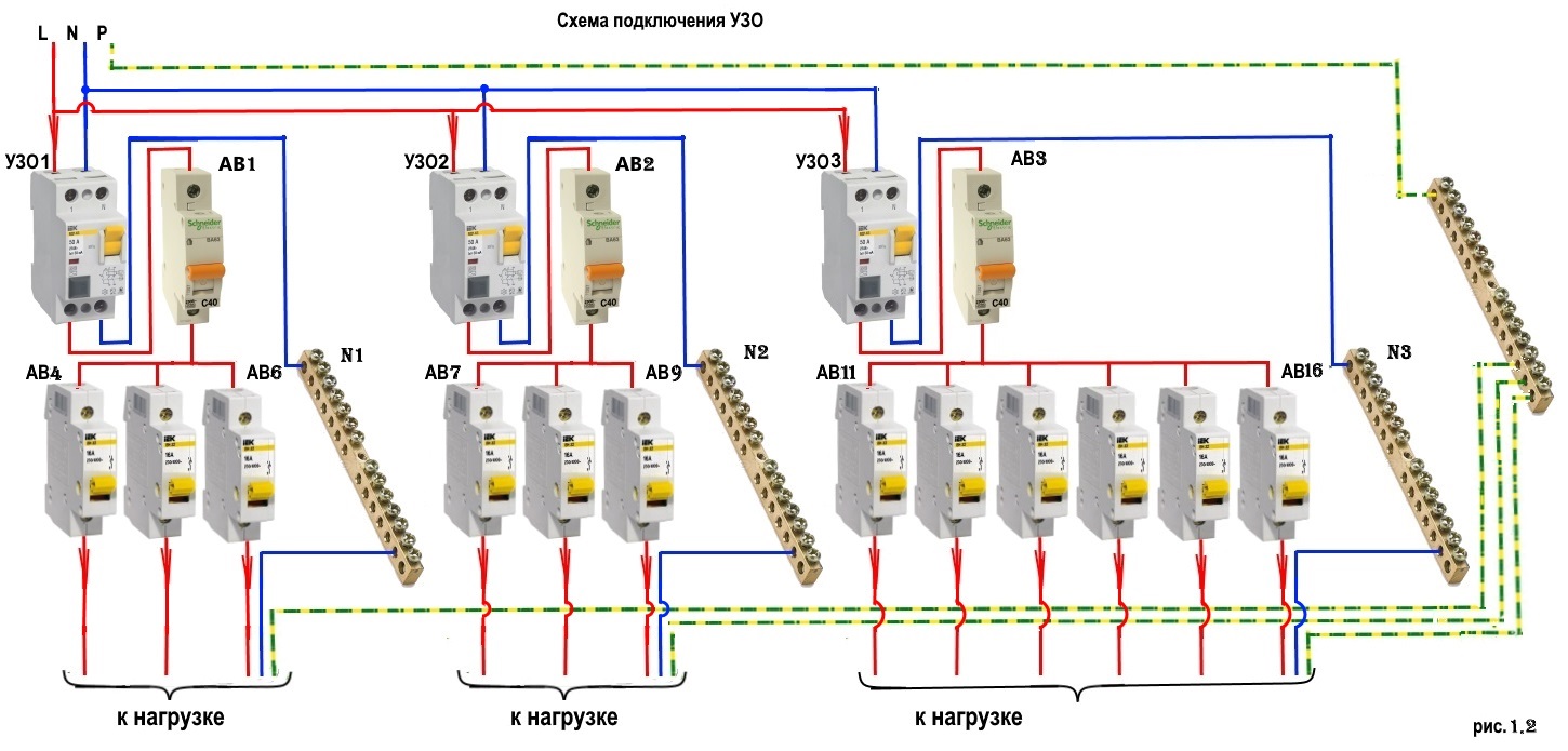
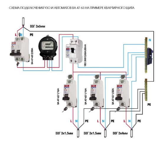
The beginning of the distribution of the electrical network is the introductory circuit breaker. A bipolar 40 Amp VA is being installed with a maximum load of 8.8 kW.Further, the phase and zero contacts are sent to the electric meter. This scheme provides electric meter installation at 5-60 amps. The remaining contacts are output to the load. When planning the installation of a fire protection RCD, we select a rating of 300 mA / 50Amps. Thus, the magnitude of the current flow through the fire must be one step higher than the rating that the introductory circuit breaker has.
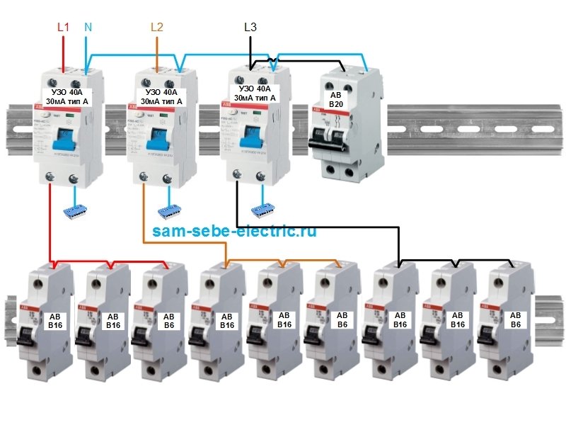
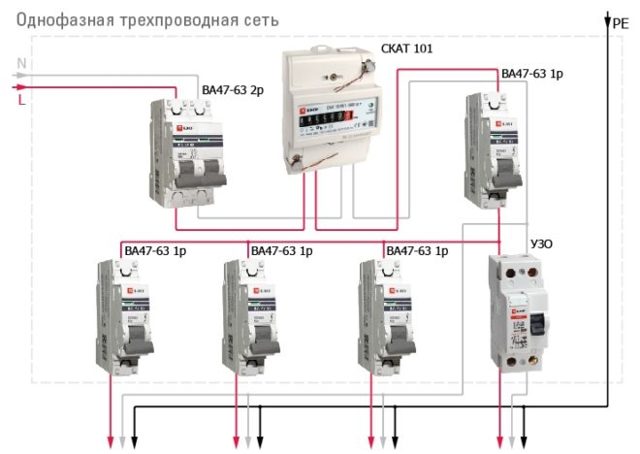
Pay attention to the connection diagram of a three-phase ouzo:
It should be noted that fire fighting is not able to protect a person from electric shock. However, it protects the wiring of a building with a leakage current sensitivity of 300mA, which implies a coarse cutoff. As a result, a short circuit and possible fire will be prevented by de-energizing the entire object until the current leakage is eliminated.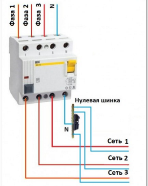
Installation and connection of elements
All modern machines and RCDs have a unified mount for a standard mounting rail (DIN rail). On the back side they have a plastic stop that snaps onto the bar. Put the device on the rail, hooking it with a notch on the back wall, press the bottom part with your finger. After clicking, the element is set. It remains to connect it. They do it according to the plan. The corresponding wires are inserted into the terminals and the contact is pressed with a screwdriver, tightening the screw. It is not necessary to tighten it strongly - you can transfer the wire.
They work when the power is off, all switches are switched to the “off” position. Try not to grab the wires with both hands.Having connected several elements, turn on the power (input switch), then turn on the installed elements in turn, checking them for the absence of a short circuit (short circuit).
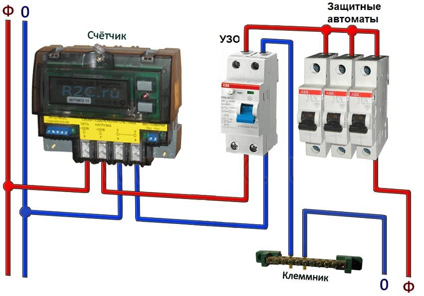
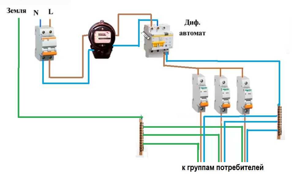
Connection of the input machine and RCD
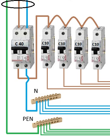
The phase from the input is fed to the input machine, from its output it goes to the corresponding input of the RCD (put a jumper with a copper wire of the selected section). In some circuits, the neutral wire from the water is fed directly to the corresponding input of the RCD, and from its output it goes to the bus. The phase wire from the output of the protective device is connected to the connecting comb of the machines.
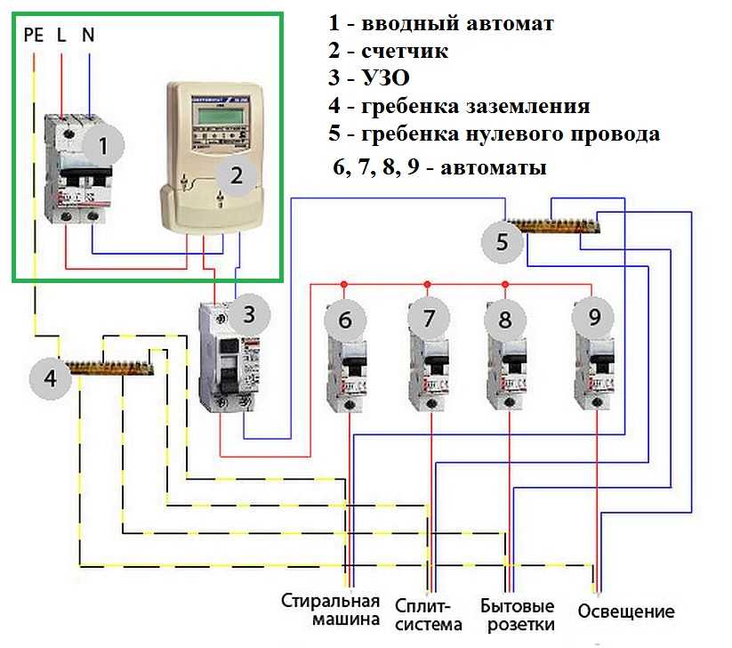
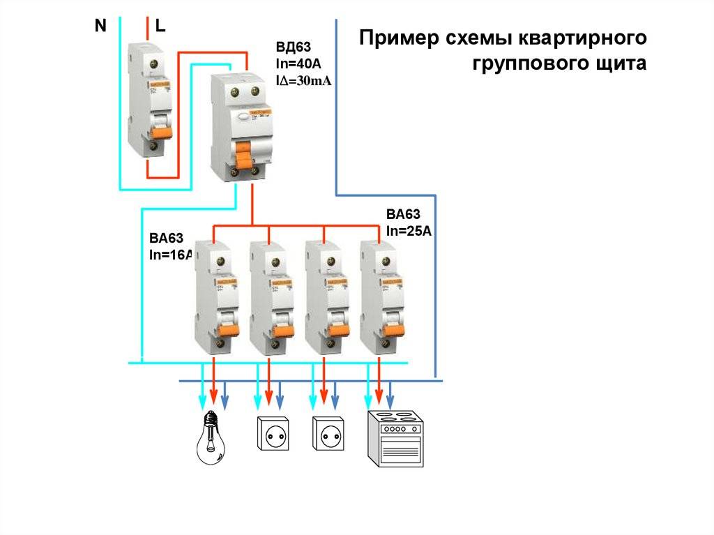
In modern circuits, the input automaton is set to two-pole: it must simultaneously turn off both wires (phase and zero) in order to completely de-energize the network in the event of a malfunction: it is safer and these are the latest electrical safety requirements. Then the RCD switching circuit looks like in the photo below.
When using a two-pole input breaker
See the video for installing an RCD on a DIN rail.
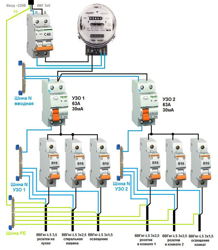
In any scheme, the protective ground wire is connected to its own bus, where similar conductors from electrical appliances are connected.
The presence of grounding is a sign of a safe network and it is vital to do it. Literally
For information on how to properly connect the RCD, see the video tutorial.
When assembling the shield yourself, please note that the input machine and the meter will be sealed by the energy supply organization. If the meter has a special screw on which a seal is attached, then the input machine does not have such devices. If it is not possible to seal it, you will either be denied launch, or the entire shield will be sealed.Therefore, inside the common shield they put a box in one or two places (depending on the size and type of the machine), and an input machine is attached to it. This box is sealed upon acceptance.
Individual machines are installed on rails exactly like RCDs: they are pressed against the rail until they click. Depending on the type of machine (one or two poles - wires), the corresponding wires are connected to them. What are the machines, and how do devices for a single and three-phase network differ, see the video, the choice of the rating of the circuit breaker is described here.
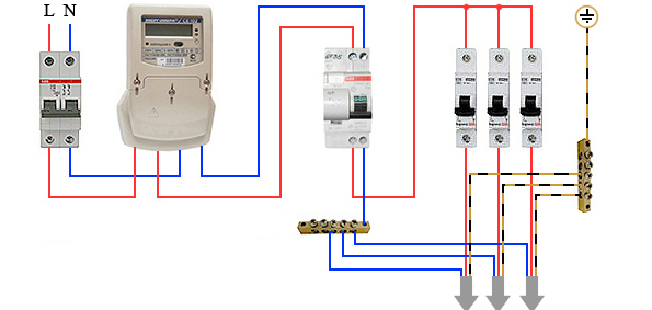
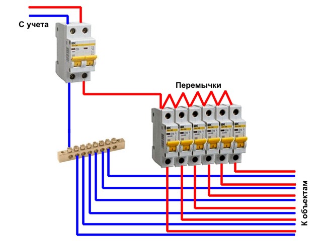
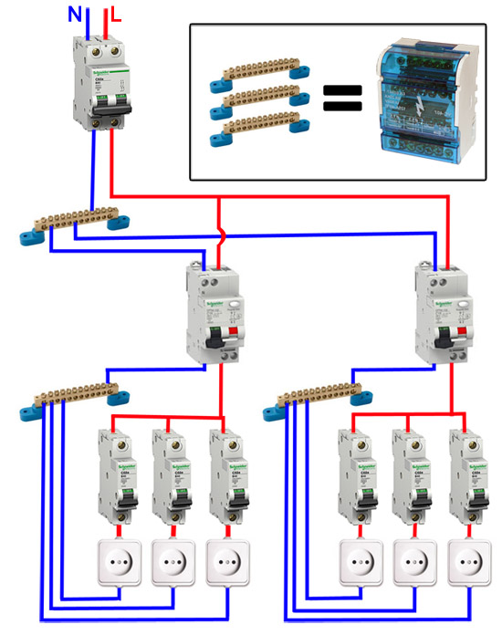
After the required number of devices are installed on the mounting rail, their inputs are connected. As mentioned earlier, this can be done with wire jumpers or a special connecting comb. How the wire connection looks like, see the photo.
Automata in one group are connected by jumpers: the phase comes in common
There are two ways to make jumpers:
- Cut the conductors of the desired segments, expose their edges and bend with an arc. Insert two conductors into one terminal, then tighten.
- Take a sufficiently long conductor, after 4-5 cm, strip 1-1.5 cm of insulation. Take the round-nose pliers and bend the bare conductors so that you get interconnected arcs. Insert these exposed areas into the appropriate sockets and tighten.
They do this, but electricians talk about the poor quality of the connection. It is safer to use special tires. Under them on the case there are special connectors (narrow slots, closer to the front edge), into which the bus contacts are inserted. These tires are sold by the meter, cut into pieces of the required length with ordinary wire cutters. After inserting it and installing the supply conductor in the first of the machines, twist the contacts on all connected devices.See the video on how to connect the machines in the shield using a bus.
A phase wire is connected to the output of the machines, which goes to the load: to household appliances, to sockets, switches, etc. Actually, the assembly of the shield is completed.
The difference between an electromechanical RCD with 2 and 4 windings from an electronic one
Look at the picture of the block diagrams of two types of RCDs - electromechanical and electronic. They are similar to each other, but in the electronic device circuit there is an additional element - a triangle with the letter "A" - an amplifier. As the name implies, the difference between these devices is in the design. In electromechanical devices, there are relays and a transformer with two, and in three-phase devices - four windings. With good insulation, the total current and voltage in the output winding are equal to 0. In case of damage, a voltage appears on it sufficient to trigger the protection.
In electronic devices, there is an electronic circuit with an amplifier inside. Such devices are cheaper and have higher sensitivity. The disadvantage of this design is the need to provide power to this circuit, which it receives from the network. When the neutral wire breaks, there is no voltage to power electrical appliances, but there is in the phase wire relative to grounded structures. When you touch it, a person is exposed to high voltage, and the RCD will not work due to the lack of power to the electronic circuit.
Therefore, an electromechanical relay provides more reliable protection.
RCD without power supply, and with power supply
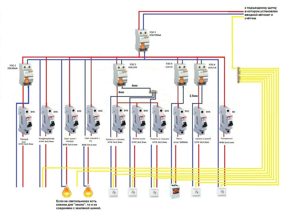
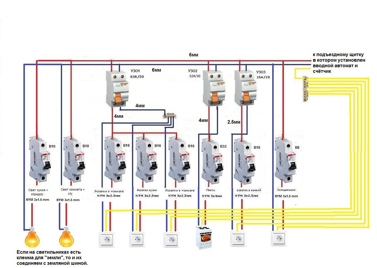
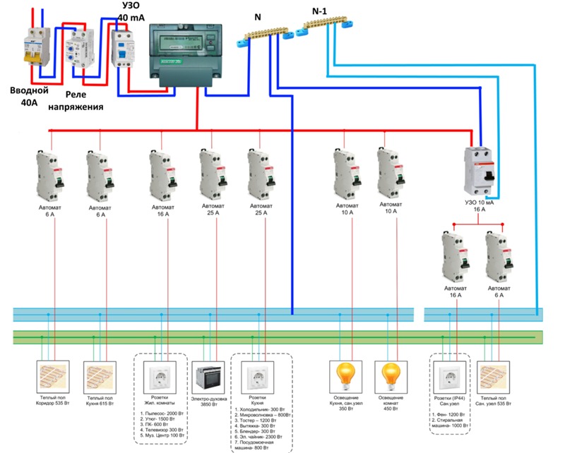
Step by step wiring diagram
Let's take a closer look at how to make electrical wiring in an apartment with your own hands. Proper design and well-thought-out wiring diagram is the key to the safety of the inhabitants of the apartment. In the process of developing a circuit, you can optimize the location of the elements of the internal network, correctly calculate the required amount of materials, and select the type of wire. Having a diagram and wiring plan will also secure in the event of a future repair, eliminating the risk of accidental damage during repairs.
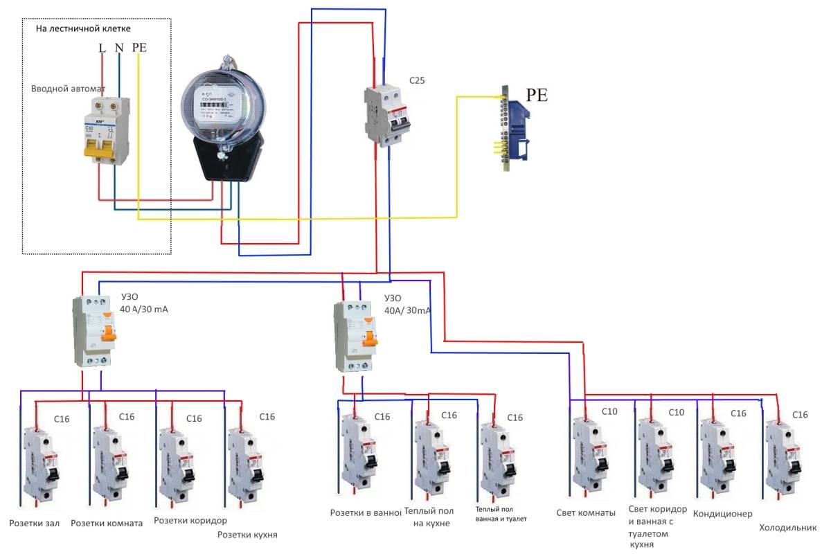
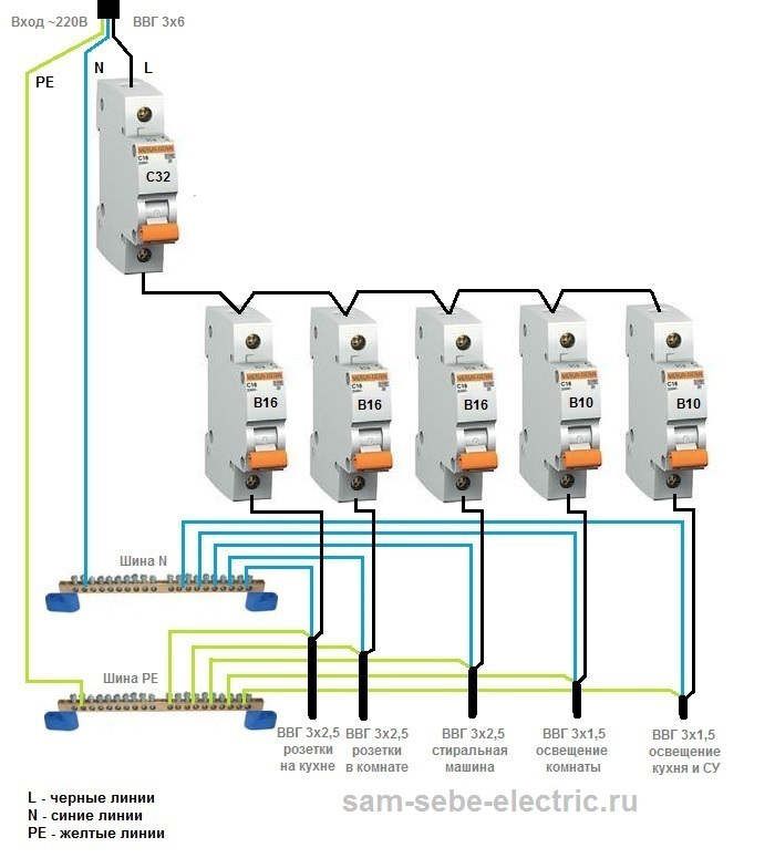
An example of a wiring diagram in an apartment with your own hands, see the photo:
With a lack of experience at this stage, it is better to turn to qualified electricians, but it is quite possible to draw up a connection diagram on your own. The plan and calculation of the internal electrical network is subject to approval by the energy inspectorate, therefore, if there are gross errors, it will have to be redone.
How to properly organize the wiring in the apartment with your own hands from scratch, see the video:
To prepare the scheme, you will need a drawing and a plan of the apartment. The plan should indicate the proposed location of furniture and large household appliances. Guided by the requirements of the PUE, lighting points, sockets and switches are marked on the drawing.
In modern practice, the connection is made by groups of points. In each room (with the exception of the kitchen) there are two such groups: lighting and socket. There may be more connection groups in the kitchen, since it is recommended to connect the electric stove and some other powerful electrical appliances as a separate group.
In order to save materials, connection groups may look different:
- Lighting group of rooms, corridor and kitchen;
- Lighting group of the bathroom;
- Outlet group of the corridor and rooms;
- Outlet group of the kitchen;
- Electric stove.
If there is a floor heating system or other stationary heating appliances, a separate connection group is provided for each of them.
At the wiring design stage, the power consumption and the estimated current strength in the network are calculated. This is necessary for the correct selection of the RCD and the cross section of the wires. When calculating the total power, absolutely all electrical appliances available in the apartment are taken into account, up to the hair dryer and electric razor. The wiring must withstand the simultaneous switching on of all current consumers. To determine the calculated current strength, the result is divided by 220.

A residual current device must be installed on the trunk for each connection group.
Types of RCD
RCDs are different - three-phase and single-phase ... But the division of RCDs into subclasses does not end there. At the moment, there are 2 fundamentally different categories of RCDs on the market:
- electromechanical (network independent),
- electronic (depending on the network).
Consider separately the principle of operation of each of the categories.
Electromechanical RCDs
The ancestors of RCDs are electromechanical. Based on the principle of precision mechanics i.e. looking inside such an RCD, you will not see op-amp comparators, logic, and the like.
- Consists of several main components:
- The so-called zero-sequence current transformer, its purpose is to track the leakage current and transfer it with a certain Ktr to the secondary winding (I 2), I ut \u003d I 2 * Ktr (a very idealized formula, but reflecting the essence of the process).
- A sensitive magnetoelectric element (which is locked, i.e., when triggered without external intervention, cannot return to its original state - a latch) - plays the role of a threshold element.
- Relay - provides tripping in case the latch is triggered.
This type of RCD requires high-precision mechanics for a sensitive magnetoelectric element. At the moment, only a few global companies sell electromechanical RCDs. Their cost is much higher than the price of electronic RCDs.
Why, then, in most countries of the world, it was electromechanical RCDs that became widespread? Everything is very simple - this type of RCD will work if a leakage current is detected at any voltage level in the network.
Why is this factor (independence of the mains voltage level) so important?
This is due to the fact that when using a working (serviceable) electromechanical RCD, we guarantee that in 100% of cases the relay will operate and, accordingly, turn off the power supply to the consumer.
In electronic RCDs, this parameter is also large, but not equal to 100% (as will be shown below, this is due to the fact that at a certain level of mains voltage, the electronic RCD circuit will not work), and in our case, every percent is possibly human lives (whether a direct threat to human life when they touch the wires, or indirect, in the event of a fire from burning the insulation).
In most of the so-called “developed” countries, electromechanical RCDs are a standard and a mandatory device for widespread use. In our country, there are gradual moves towards the mandatory use of RCDs, however, in most cases, the consumer is not given information about the type of RCD, which entails the use of cheap electronic RCDs.
Electronic RCDs
Any construction market is flooded with such RCDs. The cost for electronic RCDs is sometimes lower than for electromechanical ones up to 10 times.
The disadvantage of such RCDs, as already mentioned above, is not a 100% guarantee with a good RCD to get it tripped as a result of the appearance of a leakage current. Advantage - cheapness and availability.
In principle, an electronic RCD is built according to the same scheme as an electromechanical one (Fig. 1). The difference lies in the fact that the place of a sensitive magnetoelectric element is occupied by a comparison element (comparator, zener diode). For the performance of such a circuit, you will need a rectifier, a small filter, (perhaps even ROLL).
Because the zero-sequence current transformer is step-down (tens of times), then a signal amplification circuit is also needed, which, in addition to the useful signal, will also amplify the interference (or the unbalance signal present at zero leakage current). From the foregoing, it is obvious that the moment the relay operates in this type of RCD is determined not only by the leakage current, but also by the mains voltage.
If you cannot afford an electromechanical RCD, then it is still worth taking an electronic RCD, because. it will work in most cases.
There are also cases when it does not make sense to buy an expensive electromechanical RCD. One of such cases is the use of a stabilizer or an uninterruptible power supply (UPS) when powering an apartment / house. In this case, it makes no sense to take an electromechanical RCD.
I note right away that I am talking about RCD categories, their pros and cons, and not about specific models. You can buy low-quality RCDs of both electromechanical and electronic types. When buying, ask for a certificate of conformity, because.many electronic RCDs on our market are not certified.
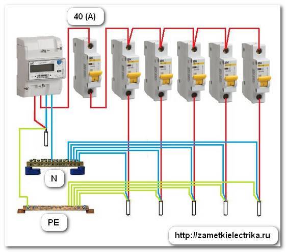
Step-by-step instructions for implementing protection
For complete information regarding the connection of devices that provide a protective cutoff, we will consider step by step the process of creating a communication circuit with the introduction of a protection device:
- Bring a power cable to the electrical panel from the centralized interface for entering energy into the house.
- Mount a circuit breaker inside the shield (this device is pre-calculated for cutoff according to the total network load).
- Mount the electric meter in a convenient place and connect the output of the machine to the input terminals of the meter.
- Install the RCD inside the shield and connect the input of the device (upper terminals) to the output terminals of the electric meter.
- Connect the phase conductor of the home electrical wiring to the output (phase) terminal of the RCD.
- Connect the neutral conductor of the home electrical wiring to the output (zero) terminal of the RCD.
- Connect the main cable to the input circuit breaker terminals.
When performing the marked operations, some nuances should be taken into account. For example, it is necessary to follow the rule of sequential connection of a circuit breaker with a protective cut-off device.
If it is not planned to introduce an automatic machine into the network, it is imperative to install fuses instead of the automatic machine.
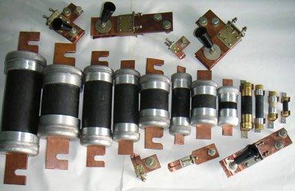
Fusible links that can be used to protect electrical circuits against short circuit currents. Fusible elements can sometimes be used for protection, replacing the functions of circuit breakers
As a rule, the value of the rated current of the protective module is recommended to be taken slightly higher than the value of the current of the circuit breaker.In some cases, this parameter can be chosen equal to the parameters of the machine.
When carrying out work on the inclusion of a protective device in the supply network, it is recommended to check all available circuits for possible defects. After installing the device, be sure to check the cut-off efficiency. For this operation, there is a special test key on the front panel of the device.
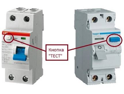
Keys for testing the correct operation of the protection. After installing and connecting the RCD, you should use these elements of the device to check the protective function
During installation, all connection work must be carried out carefully.
The supply of network lines should be made in strict accordance with the designations present on the device case. That is, the phase is connected to "phase" and, accordingly, zero is connected to "zero". From a change in the places of the “terms”, there is a high risk of failure of the protective device.
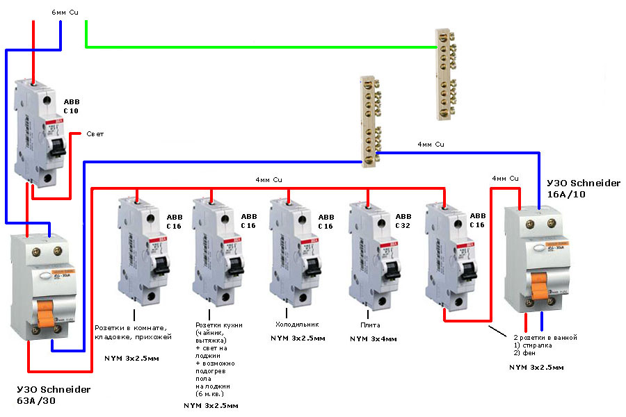
Wiring diagrams
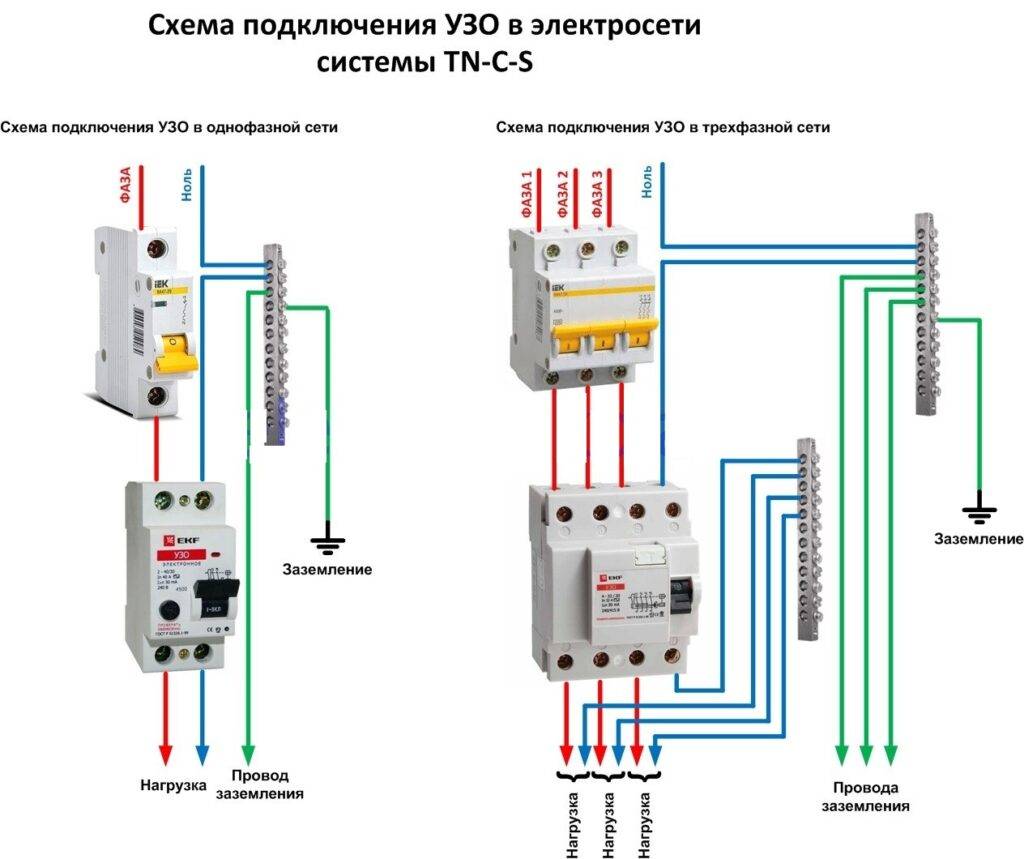
Here are the main schemes for connecting SPDs, depending on the design of grounding systems, using the models from Schneider Electric as an example. Wiring diagram of a single-phase SPD in a TT or TN-S system:
The most important thing here is not to confuse the connection point of the N-PE plug-in cartridge. If you plug it into a phase, you will create a short circuit.
Scheme of a three-phase SPD in a TT or TN-S system:
Wiring diagram for a 3-phase device in a TN-C system:
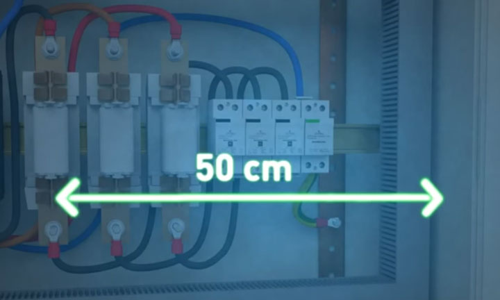
What do you need to pay attention to? In addition to the correct connection of the neutral and phase conductors, the length of these same wires plays an important role. From the connection point in the terminal of the device to the ground bar, the total length of the conductors must be no more than 50cm!.From the connection point in the terminal of the device to the ground bar, the total length of the conductors must be no more than 50cm!
From the connection point in the terminal of the device to the ground bar, the total length of the conductors must be no more than 50cm!
And here are similar schemes for SPDs from ABB OVR. Single phase option:
Three-phase circuit:
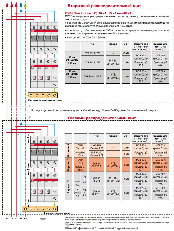
Let's go through some schematics separately. In the TN-C circuit, where we have combined protective and neutral conductors, the most common protection solution is to install an SPD between phase and ground.
Each phase is connected through an independent device and operates independently of the others.
In the variant of the TN-S network, where the neutral and protective conductors have already been separated, the circuit is similar, but here an additional module is mounted between zero and ground. In fact, the entire main blow falls on him.
That is why, when choosing and connecting the N-PE SPD, individual characteristics for impulse current are indicated. And they are usually larger than the phase values.
In addition, do not forget that lightning protection is not only a properly selected SPD. This is a whole range of activities.
They can be used both with and without lightning protection on the roof of the house.

Particular attention should be paid to a high-quality ground loop. One corner or pin hammered into the ground to a depth of 2 meters will obviously not be enough here. A good ground resistance should be 4 ohms
A good ground resistance should be 4 ohms.
Conclusions and useful video on the topic
This video concludes an article about devices used as protective systems for electrical networks, equipment and users of apartments and private houses.Review material with all the subtleties of use, which will certainly come in handy for practice.
Connecting an RCD without grounding in modern-style apartments is not only not recommended, but also prohibited. If there is a need to install equipment in the electrical panel, be sure to contact the master serving the house. All work regarding the filling of the general apartment shield must be carried out by a qualified specialist.
Tell us about how you connected a residual current device to interrupt the power supply in the event of a dangerous situation. It is possible that your advice will be very useful to site visitors. Please leave comments in the block below, post photos, ask questions.


