- Troubleshooting
- Repair of a replaced gas column heat exchanger
- Restoring the flanges of the gas column pipe by soldering
- Full disassembly service
- How to remove the heat exchanger and column burner
- Flushing procedure
- There is a spark, but no ignition
- Cleaning the heat exchanger, descaling
- Thermocouple for a gas boiler: principle of operation, characteristics, troubleshooting
- Why gas stove thermocouple?
- Types of temperature sensors
- Thermoelectric flame sensor device
Troubleshooting
If these methods do not bring the desired result, a detailed inspection and competent troubleshooting are necessary. You can contact us, we produce
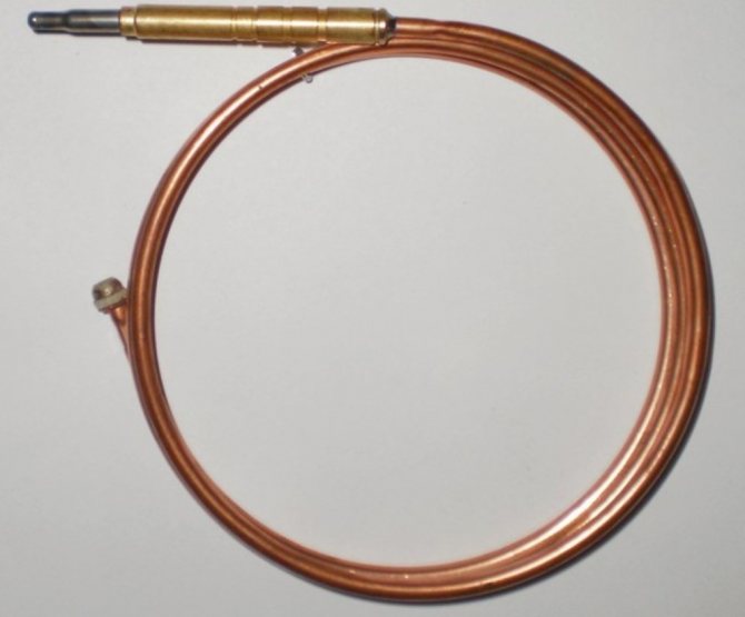
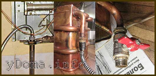
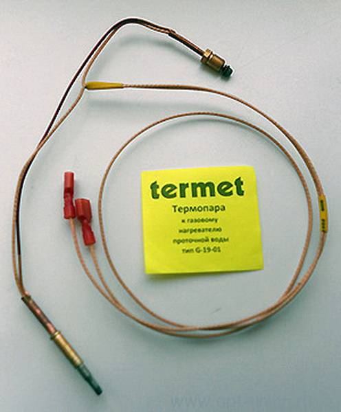
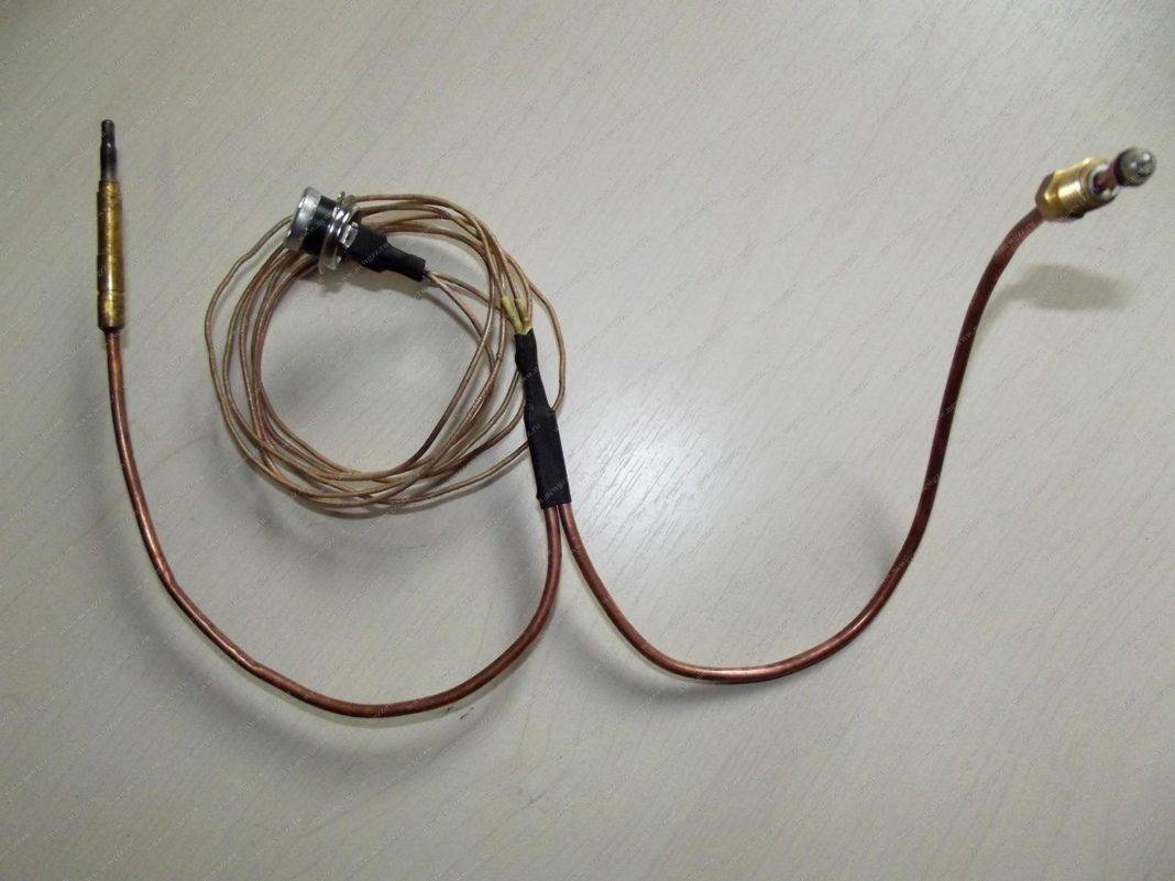
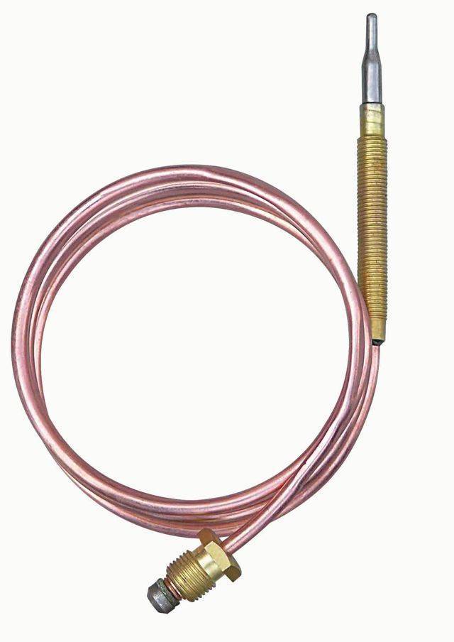
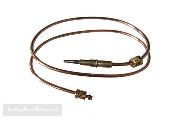
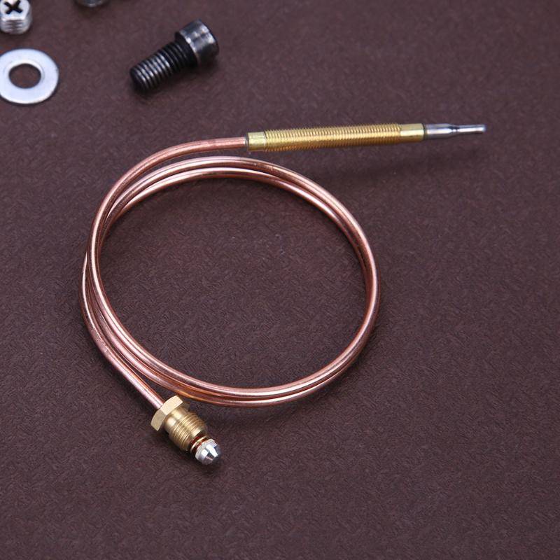
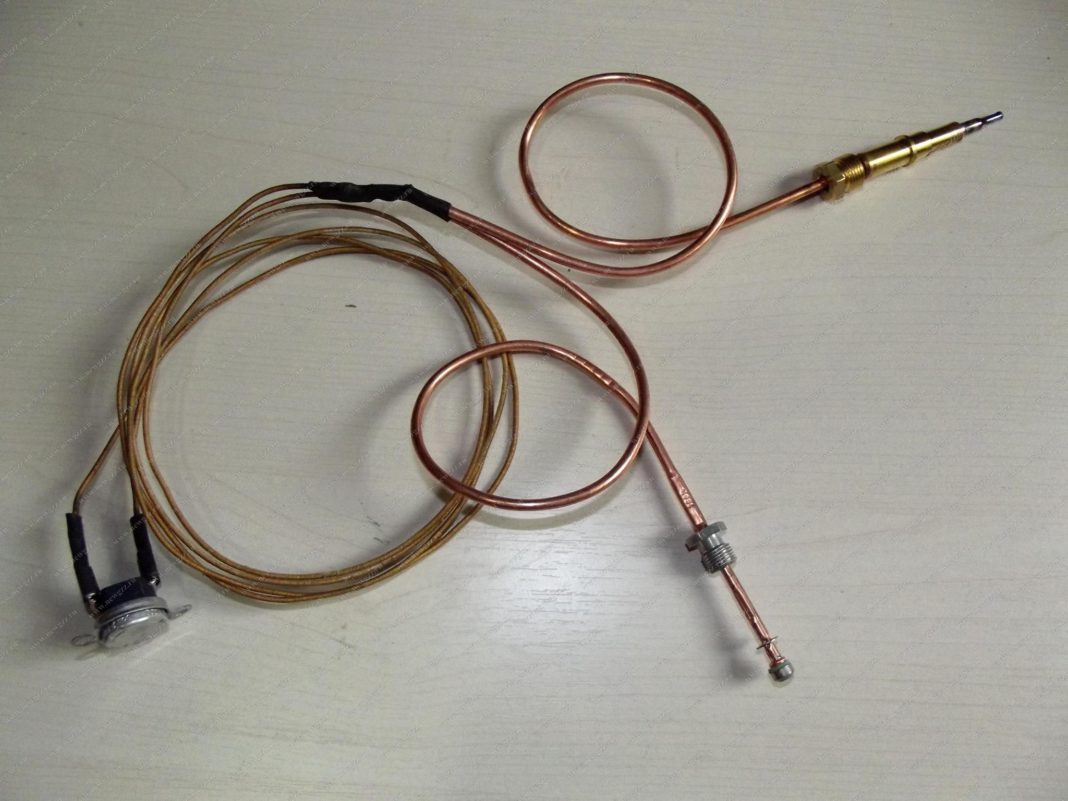
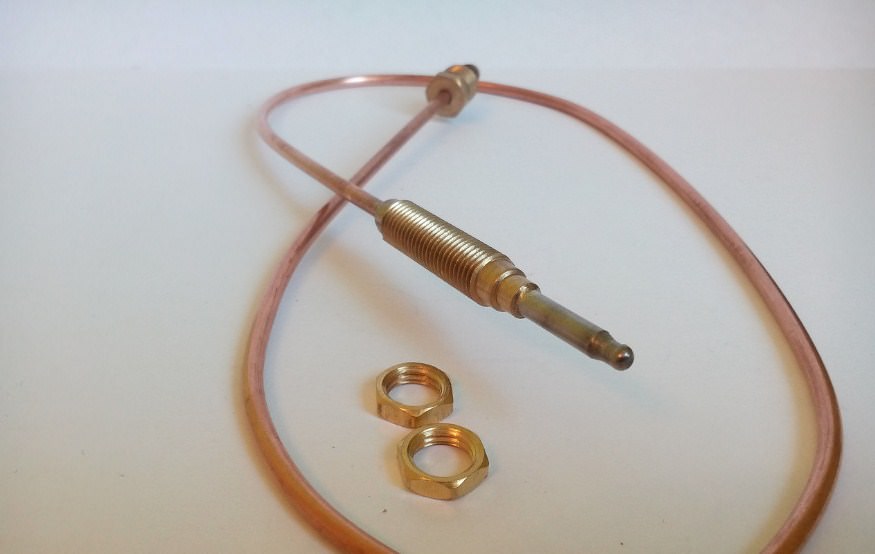
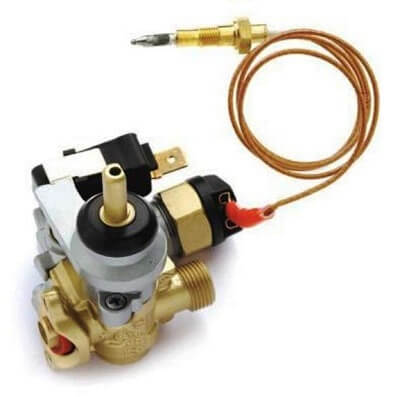
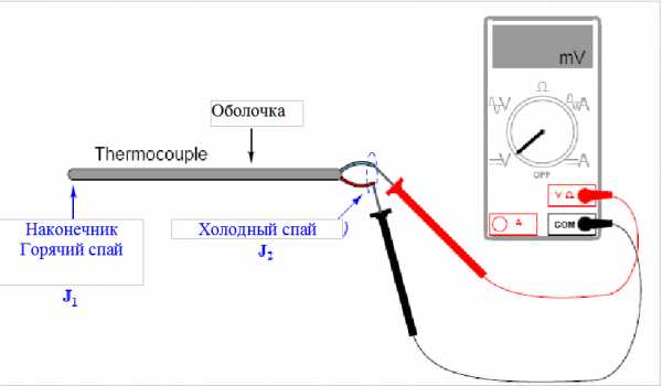
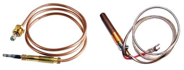
To ensure the safe operation of gas heaters with an open flame, electrical circuits are currently used, as a rule, in which a thermocouple serves as a temperature sensor. A thermocouple is a junction of two wires made of different conductors (metals). Due to the simplicity of the device, the thermocouple is a very reliable element of the protection circuit and has been working flawlessly in gas appliances for many years. The appearance of a thermocouple with wires for a gas column NEVA LUX-5013 is shown in the picture below.
The thermocouple appeared in 1821 thanks to the discovery of the German physicist Thomas Seebeck. He discovered the phenomenon of the occurrence of EMF (electromotive force) in a closed circuit when the contact point of two conductors from different metals is heated. If the thermocouple is placed in a flame of burning gas, then when it is strongly heated, the EMF generated by the thermocouple will be sufficient to open the solenoid valve for supplying gas to the burner and igniter. If the gas burning stops, the thermocouple will quickly cool down, as a result of which its EMF will decrease, and the current strength will not be enough to keep the solenoid valve open, the gas supply to the burner and the igniter will be shut off.
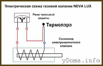
The photo shows a typical electrical circuit for protecting a geyser. As you can see, it consists of only three elements connected in series: a thermocouple, an electromagnetic valve and a thermal protection relay. When heated, the thermocouple generates an EMF, which is fed through the thermal protection relay to the solenoid (coil of copper wire). The coil creates an electromagnetic field that draws a steel anchor into it, which is mechanically connected to the gas supply valve to the burner. The thermal protection relay is usually installed in the upper part of the gas column next to the umbrella, and it serves to stop the gas supply in case of insufficient draft in the gas outlet channel. If any element of the gas column protection circuit fails, the gas supply to the burner and the igniter stops.
Depending on the model of the gas column, a manual or automatic method of igniting the gas in the igniter is used. When lighting the wick manually, matches, electric lighters (in older models of gas water heaters) or piezoelectric ignition, activated by pressing a button, are used.By the way, if the piezoelectric ignition has stopped working, then you can successfully ignite the gas in the igniter with a match.
In geysers with automatic ignition, the ignition of the gas in the burner occurs without human intervention, it is enough to open the hot water tap. For the operation of automation, an electronic unit with a battery is installed in the column. This is a disadvantage, since if the battery fails, it will be impossible to ignite the gas in the column.
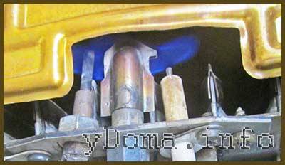
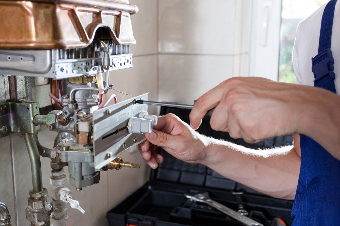
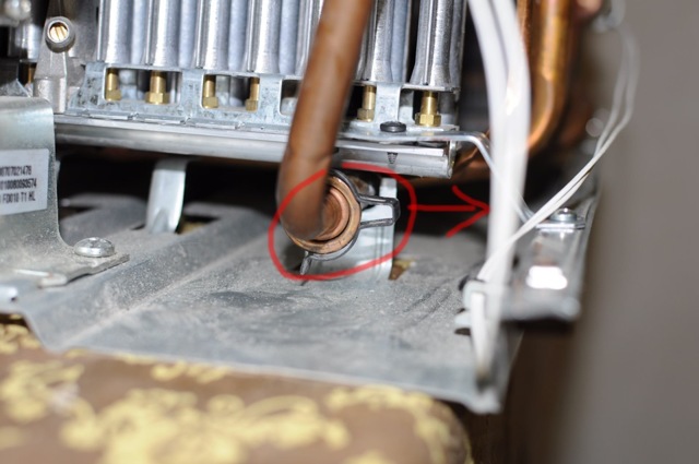
In order to ignite the gas in the igniter using a piezoelectric element, it is necessary to turn the knob on the gas stove open the gas supply to the igniter, actuate the piezoelectric element to create a spark in the arrester and after igniting the gas in the igniter, hold this knob pressed for about 20 seconds until the thermocouple heats up. This is very inconvenient, so many, including myself, do not extinguish the flame in the igniter for months. As a result, the thermocouple is always exposed to the high temperature of the flame (in the photo the thermocouple is located to the left of the igniter), which reduces its service life, which I had to deal with.
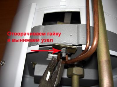
The gas column stopped igniting, the igniter went out. From a spark from a candle, the gas in the igniter ignited, but as soon as the gas supply adjustment knob was released, despite the length of time it was held down, the flame went out. Connecting the terminals of the thermal relay to each other did not help, which means that the matter is in the thermocouple or solenoid valve. When I removed the casing from the gas column and moved the central wire of the thermocouple, it fell apart, which can be clearly seen in the picture above.
Repair of a replaced gas column heat exchanger
For almost three years, the NEVA LUX-5013 gas water heater worked properly after replacing the heat exchanger, but happiness was not eternal, and suddenly water began to drip from it. I had to redo the repair.
Removing the casing confirmed my fears: a green spot appeared on the outside of the heat exchanger tube, but it was dry, and the fistula from which water oozed was on the side inaccessible for inspection and soldering. I had to remove the heat exchanger for repair.
When looking for a fistula on the back of the removed heat exchanger, a problem arose. The fistula was at the top of the heat exchanger tube and water oozed from it and flowed along all the tubes below. As a result, all the turns of the tube below the fistula turned green on top and were wet. Whether this was a single fistula or there were several, it was impossible to determine.
After the green coating had dried, it was removed from the surface of the heat exchanger using fine sandpaper. An external examination of the heat exchanger tube did not reveal blackened dots. To search for leaks, it was necessary to pressure test the heat exchanger under water pressure.
To supply water to the heat exchanger, the above-mentioned flexible hose from the shower head was used. One end of it was connected through a gasket to the water pipe for supplying water to the gas column (in the photo on the left), the second was screwed to one of the ends of the heat exchanger tube (in the photo in the center). The other end of the heat exchanger tube was plugged with a water tap.


As soon as it was opened water supply valve for gas column, immediately in the alleged places of the presence of fistulas, drops of water appeared. The rest of the tube surface remained dry.
Before soldering the fistulas, it is necessary to disconnect the flexible hose from the water supply network, open the plug valve and drain all the water from the heat exchanger by blowing it out.If this is not done, then the water will not allow the soldering place to be heated to the desired temperature, and the fistula will not be able to be soldered.
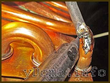
For soldering the fistula, which was located on the bend of the heat exchanger tube, I used two soldering irons. One, whose power is 40 W, led the tube under the bend for its additional heating, and the second, with a hundred-watt, performed soldering.
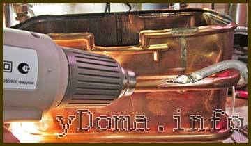
I recently purchased a construction hair dryer for the household, and soldered the fistula in a straight section, warming up the place of soldering them additionally. It turned out that soldering with a hairdryer is much more convenient, since copper warmed up faster and better. The soldering turned out to be more accurate. It’s a pity I didn’t try to solder the fistula without a soldering iron, using only a building hair dryer. The temperature of the air from the hair dryer is about 600 ° C, which should be enough to heat the heat exchanger tube to the melting temperature of the solder. I'll check it out next time I repair.
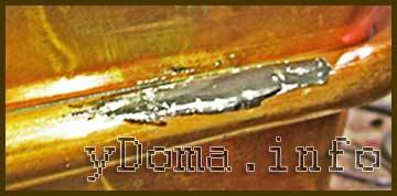
After repair, the place of the heat exchanger tube, where the fistula is located, is covered with a millimeter layer of solder, and the water path is reliably blocked. Repeated pressure testing of the heat exchanger showed the tightness of the tube. Now you can assemble the gas column. Water will no longer drip.
I bring to your attention a short video on how to solder a gas column radiator.
It should be noted that with the help of the presented technology, it is possible to successfully repair not only gas column heat exchangers, but also copper heat exchangers and radiators of any other types of water heating and cooling devices, including copper radiators installed in cars.
Restoring the flanges of the gas column pipe by soldering
Somehow, two pieces of copper tubes with flanges caught my eye, on which American union nuts were put on. These parts are designed for the installation of water pipes from copper pipes.
When soldering the gas column heat exchanger, I remembered them, and the idea arose to restore the previously cracked copper pipe connecting the heat exchanger outlet pipe to the hot water supply, soldering new flanges to them, which were idly gathering dust on the shelf. The task was somewhat more complicated, since the available parts had a copper tube bent at a right angle. I had to take up a hacksaw for metal.
First, a part of the tube with a flange was sawn off in the place where the bend begins. Further, an expanded part of the tube was sawn off from the opposite end for further use as a connecting ring. If the tube were straight, then there would be no need to cut. The result was two pieces of tube about a centimeter long.
The next step is sawing off the cracked flange from the pipe. The sawn off piece of pipe should be equal in length to the piece of pipe with the flange prepared for repair in the previous step.


As you can see in the photo, the sawn-off piece of the gas column pipe at the place where the flange was formed had many cracks.
The photo shows parts prepared for soldering. On the left - the end of the gas column pipe, on the right - a new flange with a union nut, in the middle - a connecting ring.
Before soldering, you need to check how the prepared parts fit together. The tubes of the branch pipe should enter the ring easily, with a small gap.
The mating surfaces of the tubes and the ring before soldering must first be cleaned with fine sandpaper to remove the oxide layer.It is convenient to clean the ring inside by wrapping a round rod with sandpaper, for example, the handle of a small screwdriver. Next, the cleaned surfaces must be tinned with a thin layer of POS-61 tin-lead solder using a soldering iron with a power of 60-100 watts. As a flux, it is best to use acidic zinc chloride flux, in other words, hydrochloric acid slaked with zinc. Since copper parts are soldered, rosin or aspirin is also suitable.
When soldering, it must be ensured that the pipe joint is inside the ring approximately in the middle. If, after tinning, the tubes do not want to enter the ring, then you need to heat them up with a soldering iron, the solder will melt and the tubes will enter. Do not forget to put a cap nut on the tube before soldering the pipe.
After the tubes are articulated, all that remains is to fill the gap with molten solder. As you can see in the photo, it turned out to be a completely hermetic and mechanically strong connection. The branch pipe is repaired, and you can install it in place in the gas water heater, it will serve no worse than a new one.
The check showed the tightness of the pipe at the place of soldering, but a leak occurred at its other end, for the same reason a microcrack appeared. I had to repair the other end of the pipe in the same way. The geyser has been working with a repaired pipe for more than a year. No water leaks were observed.
Using this technology, it is possible to restore the tightness of not only copper and brass tubes, but also stainless steel and iron tubes. The technology is applicable not only to repair of geysers, but also for the repair of other devices and machines, including cars.
Full disassembly service
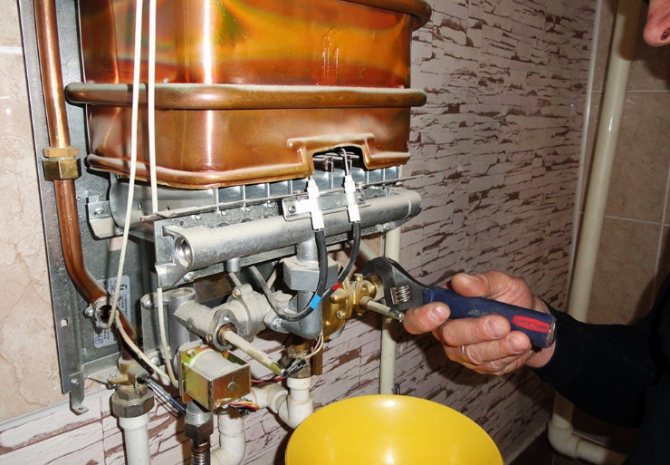
Do not be afraid to disassemble the water heater, the procedure is not so complicated.The tool will require the most common - screwdrivers, pliers, standard wrenches. What to do before starting work:
- Close the taps of the cold water, hot water and gas pipelines. Disconnect the turbocharged speaker from the outlet.
- Substituting the container, unscrew the union nuts (American) on the connection of the water pipes. Disconnect the hoses from the unit without losing the rubber seals.
- For convenience, it is recommended to remove the geyser from the wall. It is not easy to disassemble and clean the unit, suspended too high or installed in a narrow niche.
- To dismantle the water heater, turn off the gas line and the chimney pipe. Remove the unit from the hooks.
Lay the water heater on a horizontal surface and proceed to further work, whose procedure is described in our instructions.
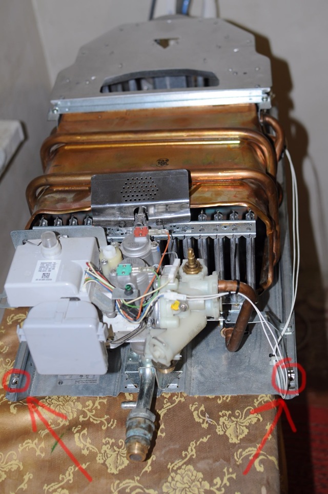
How to remove the heat exchanger and column burner
We will show the disassembly sequence using the example of a cheap Chinese Novatek water heater. We present step-by-step instructions with a photo:
- Remove the control handles mounted on the front panel. Turn out 2 self-tapping screws (or 2 plastic clips) and dismantle the casing of the device.
- The next step is to remove the smoke box. To do this, disconnect the wires from the draft sensor and unscrew the screws holding the diffuser box.
- Disconnect the heat exchanger tube from the water unit by disassembling the connection with the union nut. The second branch pipe must be released from the lock washer pressed with 2 self-tapping screws.
- Disconnect the burner from the gas valve by unscrewing the 2 screws on the flange. After moving the radiator upward, carefully remove the burner device (move towards yourself) and move it to the side.
- Remove all self-tapping screws connecting the heat exchanger to the rear panel of the boiler.
- Pull out the heat sink completely and remove the burner by disconnecting the wires together with the ignition electrodes.
Disassembly of gas water heaters from other manufacturers may differ, but not fundamentally. The order of work remains unchanged. Here are some important points:


- in a chimneyless turbocolumn, the fan will have to be dismantled;
- in units of the Italian brands Ariston (Ariston) and some others, the pipes are connected not with nuts, but with self-clamping clamps;
- if the water heater is equipped with an igniter, before removing the burner, disconnect the gas pipe connected to the wick.
The above process will be demonstrated in detail by our expert plumber in his video:
Watch this video on YouTube
Flushing procedure
This operation is very simple compared to disassembly - cleaning the gas column begins by immersing the heat exchanger in a container with washing liquid. The procedure is as follows:
- Take a bucket or deep basin, fill with water and prepare the cleaning solution according to the recipe on the package. The concentration of citric acid is 50-70 grams per 1 liter of liquid.
- Immerse the heat exchanger into the container with the radiator down and the nozzles up.
- Using a watering can, fill the coil with detergent. Flush it periodically with new solution.
- Flush the heat exchanger until a clear liquid without scale flakes comes out of the tubes. Then run tap water through the coil to remove any remaining product and impurities.
The removed burner can be cleaned from the outside and blown or washed with a solution of citric acid (no more than 50 grams per liter of water).At the end, rinse the element with running water, blow it with compressed air and dry thoroughly.
Do not ignore other parts of the geyser - a strainer, a smoke box and a combustion chamber, remove soot and other contaminants from them
After rinsing and drying, replace the heat exchanger, connect the burner and follow the rest of the steps to reassemble the water heater
It is important to achieve tight joints: when installing old gaskets, treat them with a high-temperature sealant. Check the joints for tightness with water pressure (4-6 bar). From the inside, it does not hurt to blow the burner with compressed air at a pressure of 4-6 bar
From the inside, it does not hurt to blow the burner with compressed air at a pressure of 4-6 bar
There is a spark, but no ignition
When this dilemma arises, the following factors appear:
- The valve responsible for the flow of gas is closed. Measure - turn it all the way.
- Low water pressure. It can be not only in the line, but also at the inlet to the boiler, where the filter may become clogged.
- The water is weakly fixed annuity interest rate warming up. Solution: cleaning the heat exchanger (TH). Mounts on which plaque has accumulated can be cleaned with VD-40, and the radiator can be placed in a basin with a composition based on citric acid. Then warm on the stove for half an hour, until the scale disappears completely.
- The burner is clogged. A lot of soot and soot sometimes appears in the jets. You can get rid of it with a thin copper wire.
If the piezo did not work in the Electrolux gas column or in other similar equipment, then it should be periodically checked for gas leakage using a soapy emulsion. If there are no bubbles, then everything is fine.
Cleaning the heat exchanger, descaling
One of the common malfunctions of geysers is insufficient water heating. As a rule, the reason for this is the formation of a layer of scale inside the heat exchanger tube, which prevents the water from heating up to the set temperature and reduces the water pressure at the outlet, which ultimately leads to increased gas consumption by the gas column. Scale is a poor conductor of heat and, having covered the heat exchanger tube from the inside, forms a kind of thermal insulation. The gas is open to its fullest, and the water does not warm up.
Scale is formed in case of higher hardness of tap water. What kind of water you have in the water supply is easy to find out by looking into the electric kettle. If the bottom of the electric kettle is covered with a white coating, it means that the water in the water supply is hard, and the heat exchanger is covered with scale from the inside in the same way. Therefore, it is periodically necessary to remove scale from the heat exchanger.
On sale there are special devices for removing scale and rust in hot water systems, for example, Cillit KalkEx Mobile and flushing fluids. But they are very expensive and not available for home use. The principle of operation of cleaners is simple. There is a container in which a pump is mounted, as in a washing machine for pumping water from the tank. Two tubes from the descaling device are connected to the tubes of the gas column heat exchanger. The flushing agent is heated and pumped through the heat exchanger tube, even without removing it. The scale dissolves in the reagent and the heat exchanger tubes are removed with it.


To clean the heat exchanger from scale without the use of automation tools, it is necessary to remove it and blow through the tube so that no water remains in it.Descaler, ordinary vinegar or citric acid (100 grams of citric acid powder is dissolved in 500 ml of hot water) can serve as a cleaning agent. The heat exchanger is placed in a container with water. It is enough that only a third of it is immersed in water. Completely fill the heat exchanger tube with reagent through a funnel or thin tube. It is necessary to pour into the heat exchanger tube from the end that leads to the lower coil so that the reagent displaces all the air.
Put the container on the gas stove and bring the water to a boil, boil for ten minutes, turn off the gas and let the water cool. Further, the heat exchanger is installed in the gas column and is connected only to the pipe supplying water. A hose is put on the outlet pipe of the heat exchanger, its second end is lowered into the sewer or any container. The valve for supplying water to the column opens, the water will displace the reagent with scale dissolved in it. If there is no large capacity for boiling, then you can simply pour the heated reagent into the heat exchanger and hold it for several hours. If there is a thick layer of scale, the cleaning operation may need to be repeated several times to completely remove the scale.
Thermocouple for a gas boiler: principle of operation, characteristics, troubleshooting
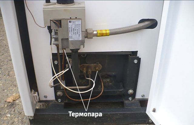
The use of gas for heating a private house or cottage is very convenient and cost-effective. However, this type of fuel is fraught with a serious threat. If, for any reason, the burner suddenly goes out and the gas supply is not shut off in time, a leak will form and this can turn into serious trouble and endanger the lives of people in the room.In order to immediately turn off the gas if the flame suddenly goes out and a thermocouple for a gas boiler is used.
In this article, we will talk about what a thermocouple is, why it is needed and how it works, consider the main types and most common malfunctions associated with these devices, as well as a method for eliminating them.
Why gas stove thermocouple?
The gas in the stove burner is ignited with matches, a manual piezo lighter or a built-in electric ignition. Then the flame should burn itself without human intervention, until the fuel is shut off by the valve.
However, fire is often gas hob or in the oven goes out as a result of a gust of wind or a splash of water from a boiled pan. And then, if there is no one nearby in the kitchen, methane (or propane) begins to flow into the room. As a result, when a certain concentration of gas is reached, cotton with fire and destruction occurs.
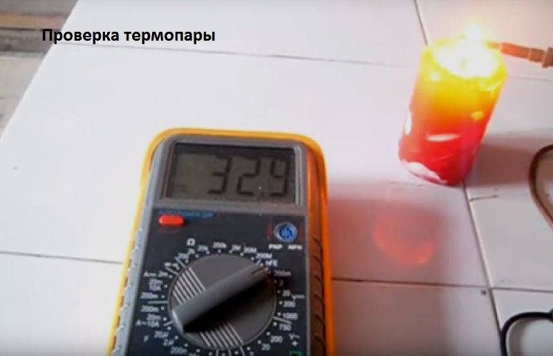
Thermocouple operating function - flame control. While the gas is burning, the temperature at the tip of the control device reaches 800–1000 0 C, and often even higher. As a result, an EMF occurs, which keeps the gas solenoid valve on the nozzle to the burner open. The burner is working.
However, when the open flame disappears, the thermocouple stops producing EMF to the electromagnet. The valve is closed and the fuel supply is turned off. As a result, the gas does not enter the kitchen without accumulating in it, which eliminates the occurrence of a fire from such an emergency situation.
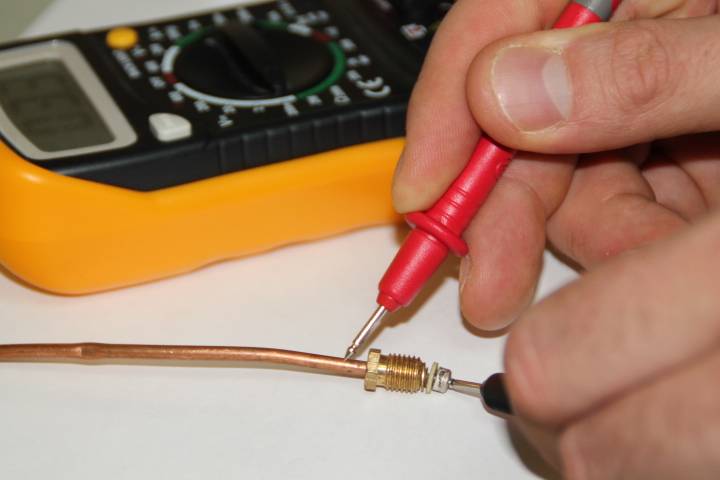
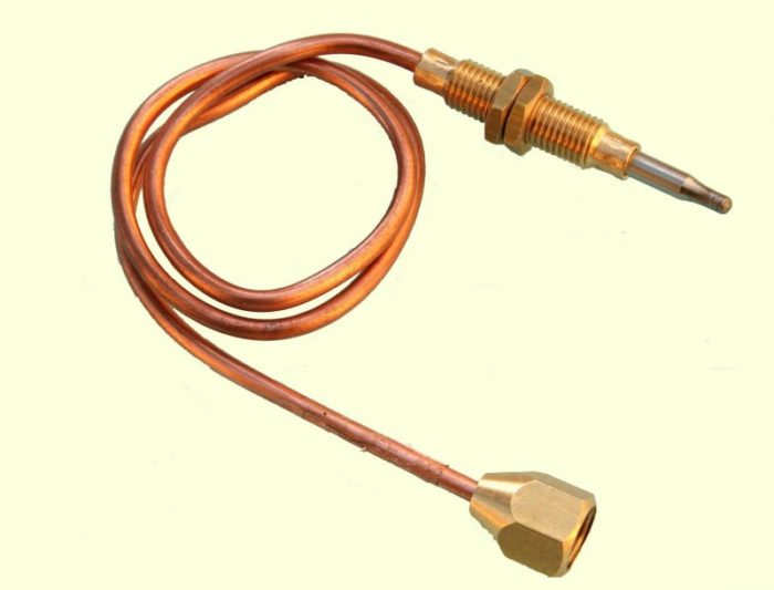
A thermocouple is the simplest temperature sensor without any electronic devices inside. There is nothing to break in it. It can only burn out from prolonged use.
The following article, which is fully devoted to this interesting issue, will acquaint you with a complete set of sensors designed to control and safety of the operation of the gas column.
Among the advantages of thermocouples:
- simplicity of the device and the absence of breaking mechanical or burning electrical elements;
- the cheapness of the device is about 800–1500 rubles, depending on the model of the gas stove;
- long service life;
- high efficiency flame temperature control;
- fast shutoff of gas;
- ease of replacement, which can be done by hand.
There is only one significant drawback of a thermocouple - the complexity of repairing the device. If the thermocouple sensor is defective, it is easier to replace it with a new one.
To repair such a device, it is necessary to weld or solder at a high temperature (about 1,300 0 C) two different metals. It is extremely difficult to achieve such conditions in everyday life at home. It is much easier to buy a new control unit for a gas stove for replacement.
Types of temperature sensors
In the production of thermoelectric sensors, various alloys of noble and common metals are used. For certain temperature ranges, specific categories of metal are used.
Based on the metal pairs used in production, thermocouples are divided into a number of types. For the operation of gas stoves, the following types of steam are most often used:
- Type E, production marking THKn, made of chromel and constantan, for operating temperatures from 0 to 600 C.
- Type J - an alloy of iron and constantan, brand TZHK, for operating temperatures from -100 to 1200 C.
- Type K, TXA brand, is produced on the basis of chromel and alumel plates, for operating temperatures from -200 to 1350 C.
- Type L, THK brand, is produced on the basis of chromel and kopel plates, for operating temperatures from -200 to 850 C.
In the protective systems of columns, stoves and boilers operating on gas fuel, as a rule, TXA temperature sensors of types K / L / J are used. Thermocouples made of noble metal alloys are produced for significant temperature conditions, which are achievable in metallurgical production and energy.


Thermoelectric flame sensor device
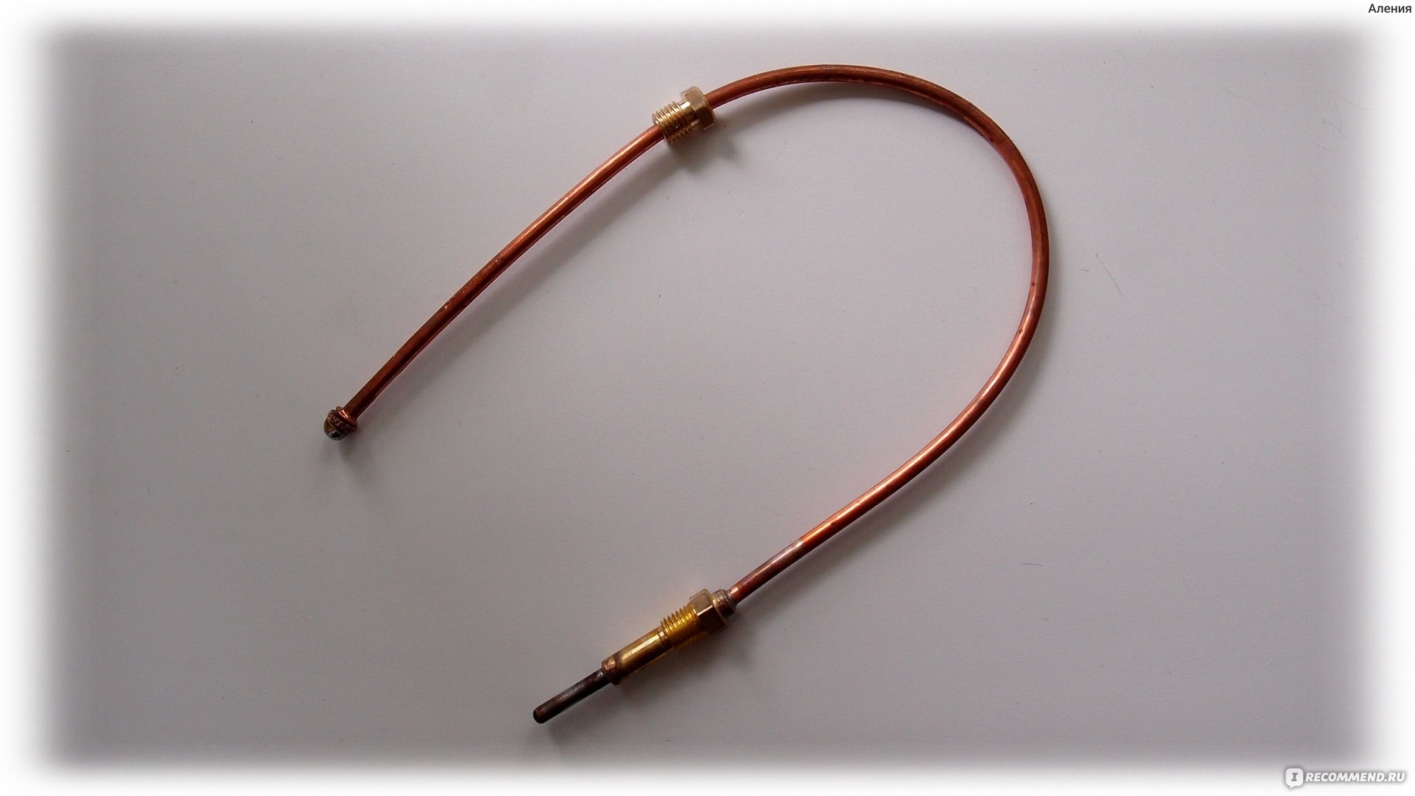
A thermocouple is a safety element of a gas boiler that generates voltage when heated and keeps the fuel supply valve open while the igniter is on. The sensor shown in the photo operates autonomously, without connecting an external power supply. The scope of thermocouples is gas-using energy-independent installations: stoves, kitchen stoves and water heaters.
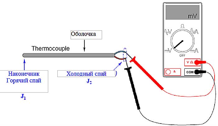
Let us explain the principle of operation of a thermocouple for a boiler, based on the Seebeck effect. If you solder or weld the ends of 2 conductors of different metals, then when this point is heated, an electromotive force (EMF) is generated in the circuit. The potential difference depends on the temperature of the junction and the material of the conductors, usually lies in the range of 20 ... 50 millivolts (for household appliances).
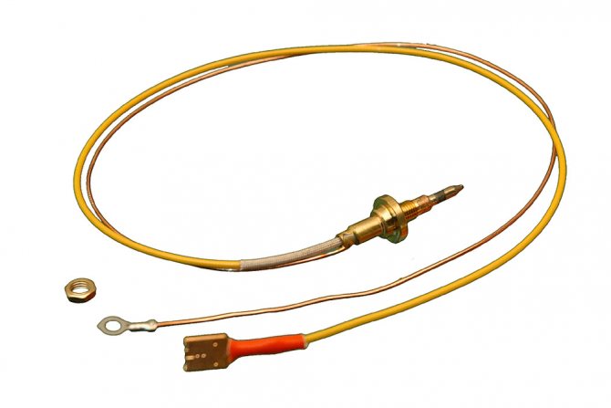
The sensor consists of the following parts (the device is shown in the diagram below):
- thermoelectrode with a "hot" junction made of two dissimilar alloys, screwed with a nut to the mounting plate next to the pilot burner of the boiler;
- extension cord - a conductor enclosed inside a copper tube, which simultaneously plays the role of a negative contact;
- positive terminal with a dielectric washer, inserted into the socket of the automatic gas valve and fixed with a nut;
- there are varieties of thermocouples that are connected to automation using conventional screw terminals.
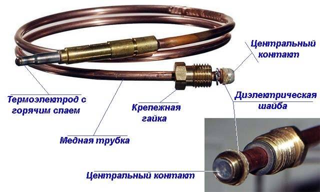
In this model, the heated electrode is attached to the boiler plate without a nut - it is inserted into a special groove
For the manufacture of electrodes that produce EMF, special metal alloys are used. The most common thermal couples:
- chromel - alumel (type K according to the European classification, designation - THA);
- chromel - kopel (type L, abbreviation - THC);
- chromel - constantan (type E, designated THKn).
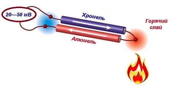
The principle of operation of a thermal couple from two different alloys
The use of alloys in the design of thermocouples is due to better current generation. If you make a thermal couple from pure metals, the output voltage will be too low. In most heat generators operated in private homes, TCA sensors (chromel - alumel) are installed. For more information about the device of thermocouples, see the video: