- Current relay device
- Connection process
- Purpose
- Connecting, adjusting and marking TP
- Device connection diagram
- Adjustment procedure
- Manual adjustment
- Device and principle of operation
- What is important to know?
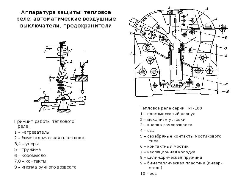
- The principle of operation of the thermal relay
- Connecting, adjusting and marking TP
- Device connection diagram
- Adjustment procedure
- Manual adjustment
- Choice of electrothermal relay
- What is a relay and where are they used?
- The device and operation of the electrothermal relay.
- Relay characteristics
Current relay device
First, let's look at the principle of a current relay and its device. At the moment, there are electromagnetic, induction and electronic relays.
We will disassemble the device of the most common electromagnetic relays. Moreover, they make it possible to most clearly understand their principle of work.
 Electromagnetic current relay device
- Let's start with the basic elements of any current relay. It must have a magnetic circuit. Moreover, this magnetic circuit has a section with an air gap. There can be 1, 2 or more such gaps, depending on the design of the magnetic circuit. There are two such gaps in our photo.
- There is a coil on the fixed part of the magnetic circuit.And the movable part of the magnetic circuit is fixed by a spring, which counteracts the connection of the two parts of the magnetic circuit.
 The principle of operation of the electromagnetic current relay
- When voltage appears on the coil, an EMF is induced in the magnetic circuit. Thanks to this, the movable and fixed parts of the magnetic circuit become like two magnets that want to connect. The spring prevents them from doing this.
- As the current in the coil increases, the EMF will increase. Accordingly, the attraction of the movable and fixed sections of the magnetic circuit will increase. When a certain value of the current strength is reached, the EMF will be so large that it will overcome the resistance of the spring.
- The air gap between the two sections of the magnetic circuit will begin to decrease. But as the instruction and logic say, the smaller the air gap, the greater the force of attraction becomes, and the faster the magnetic cores are connected. As a result, the switching process takes hundredths of a second.
 There are different types of current relays
Movable contacts are rigidly attached to the moving part of the magnetic circuit. They close with fixed contacts and signal that the current strength on the relay coil has reached the set value.
Current relay return current adjustment
To return to its original position, the current in the relay must decrease as in the video. How much it should decrease depends on the so-called relay return factor.
It depends on the design, and can also be adjusted individually for each relay by tensioning or loosening the spring. It is quite possible to do it yourself.
Connection process
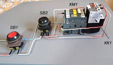
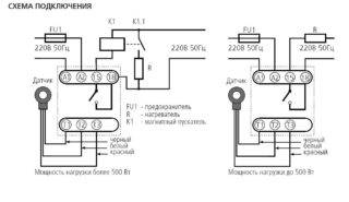
Below is a connection diagram of the TR with symbols. On it you can find the abbreviation KK1.1.It denotes a contact that is normally closed. The power contacts through which the current flows to the motor are indicated by the abbreviation KK1. The circuit breaker located in the TR is designated as QF1. When it is activated, power is supplied in phases. Phase 1 is controlled by a separate key, which is marked SB1. It performs an emergency manual stop in case of an unexpected situation. From it, the contact goes to the key, which provides a start and is indicated by the abbreviation SB2. The additional contact, which departs from the start key, is in the standby state. When starting is performed, then the current from the phase through the contact flows to magnetic starter via coil, which is denoted by KM1. The starter is triggered. In this case, those contacts that are normally open are closed and vice versa.
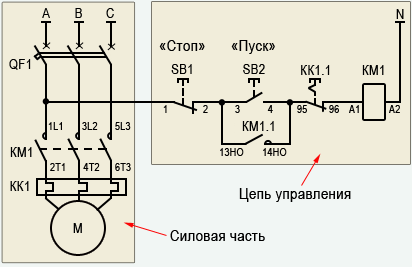
When the contacts are closed, which are abbreviated KM1 in the diagram, then three phases are turned on, which let current through the thermal relay to the motor windings, which is put into operation. If the current strength increases, then due to the influence of the contact pads TP under the abbreviation KK1, three phases will open and the starter will be de-energized, and the motor will stop accordingly. The usual stop of the consumer in forced mode occurs by acting on the SB1 key. It breaks the first phase, which will stop the voltage supply to the starter and its contacts will open. Below in the photo you can see an impromptu wiring diagram.
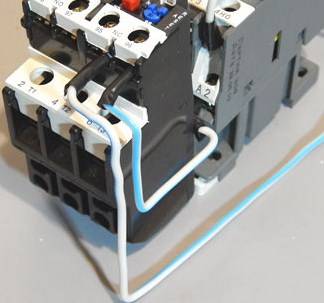
There is another possible connection scheme for this TR.The difference lies in the fact that the relay contact, which is normally closed when triggered, does not break the phase, but zero, which goes to the starter. It is used most often due to cost-effectiveness when performing installation work. In the process, the neutral contact is connected to the TR, and a jumper is mounted from the other contact to the coil, which starts the contactor. When the protection is triggered, the neutral wire opens, which leads to the disconnection of the contactor and the motor.
The relay can be mounted in a circuit where the reverse movement of the motor is provided. From the diagram that was given above, the difference is that there is an NC contact in the relay, which is designated KK1.1.
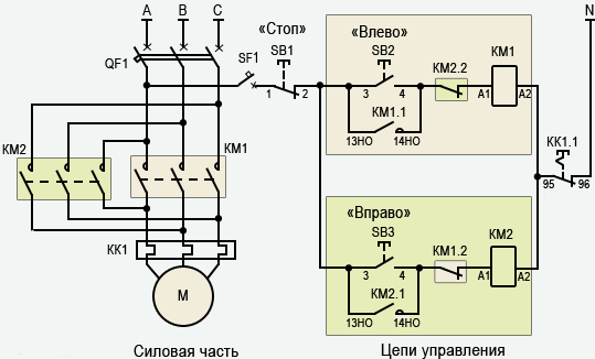
If the relay is activated, then the neutral wire breaks with contacts under the designation KK1.1. The starter de-energizes and stops powering the motor. In an emergency, the SB1 button will help you quickly break the power circuit to stop the engine. You can watch a video about connecting the TR below.


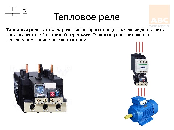
Purpose
Immediately I would like to say that there are different types and types of thermal relays and, accordingly, the scope of each classification has its own. Let's briefly talk about the purpose of the main types of devices.
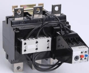
RTL - three-phase, designed to protect the electric motor from overloads, phase imbalance, prolonged start-up or rotor jamming. PML starters are mounted on contacts or as an independent device with KRL terminals.
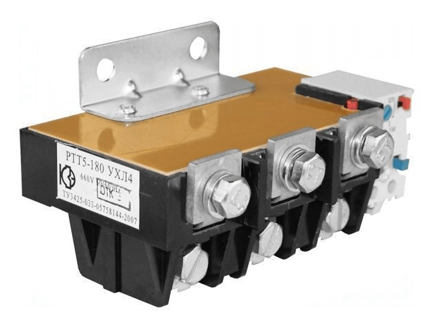
PTT - for three phases, designed to protect short-circuited motors from overload currents, phase imbalance, jamming of the motor rotor, prolonged start of the mechanism.It can be mounted on PMA and PME starters, as well as independently installed on the panel.
RTI - protect the electric motor from overload, phase asymmetry, long start-up and jamming of the machine. The three-phase thermal relay, fastens on starters of the KMT and KMI series.
TRN is a two-phase relay that controls the mode of operation and start-up, has only manual return of contacts, the operation of the device does not depend much on the ambient temperature.
Solid-state three-phase relays, do not have moving parts, do not depend on the state of the environment, are used in explosive areas. It monitors the load current, acceleration, phase failure, mechanism jamming.
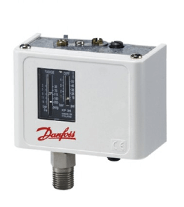
RTK - temperature control occurs with a probe located in the electrical installation housing. It is a thermal relay, and controls only one parameter.
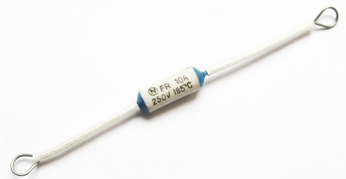
RTE - alloy melting relay, the electrically conductive conductor is made of a metal alloy, melts at a certain temperature and mechanically breaks the circuit. This thermal relay is built directly into the controlled device.
As can be seen from our article, there is a wide variety of control over the state of electrical installations that differ in type and appearance, but perform the same protection of electrical equipment. This is all that I wanted to tell you about the device, the principle of operation and the purpose of thermal relays. We hope the information was useful and interesting for you!
It will be interesting to read:
- How does a magnetic starter work
- How to choose a thermal relay
- What is the degree of IP protection
- What are time relays
Connecting, adjusting and marking TP
 It is necessary to install an electrothermal relay with a magnetic starter that connects and starts the engine. As an independent device, the device is placed on a DIN rail or mounting plate.


Device connection diagram
Connection diagrams for starters with thermal types of relays depend on the type of device:
- Series connection with motor winding or starter coil to a normally open contact (NC). The element works if it is connected to the stop key. The system is used when it is necessary to equip the engine with an alarm protection. The relay is placed after the starting contactors, but before the motor, then the NC contact is connected.
- Starter zero break by normally closed contact. The circuit is convenient and practical - zero can be connected to the TR contact, a jumper is thrown from the second contact to the starter coil. At the moment the relay is activated, there is a break in zero and a de-energization of the starter.
- Reverse scheme. The control circuit contains a normally closed and three power contacts. The electric motor is powered through the latter. When the protective mode is activated, the starter is de-energized and the motor stops.
Adjustment procedure
SAMSUNG CSC
The device is set up on specialized stands with a low-power load transformer. Heating nodes are connected to its secondary mechanisms, and the voltage is controlled using an autotransformer. The current limit of the load is adjusted by an ammeter connected through the secondary circuit.
The check is done like this:
- Turning the transformer handle to zero position with voltage applied. Then the load current is selected with the knob and the relay operation time is checked from the moment the lamp goes out with a stopwatch.The norm is 140-150 seconds at a current of 1.5 A.
- Setting the current rating. Produced when the current rating of the heater does not match the rating of the motor. Adjustment limit - 0.75 - 1.25 of the heater rating.
- Current setting setting.
For the last step, you need to calculate:
- determine the correction for the rated current without temperature compensation using the formula ±E1 = (Inom-Io)/СIo. Io - zero setting current, C - division value of the eccentric (C \u003d 0.05 for open models and C \u003d 0.055 - for closed ones);
- calculate the correction taking into account the ambient temperature E2=(t - 30)/10, where t is the temperature;
- calculate the total correction by adding the obtained values;
- round the result up or down, translate the eccentric.
Manual adjustment
You can manually adjust the thermal relay. The value of the trip current can be set in the range from 20 to 30% of the nominal value. The user will need to smoothly move the lever to change the bending of the bimetal plate. The trip current is also adjustable after replacement of the thermal assembly.
Modern switches are equipped with a test button to search for a breakdown without using the stand. Using the reset key, you can reset the settings in automatic or manual mode. An indicator is used to track the status of the device.
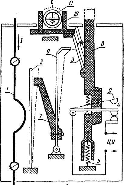
Device and principle of operation
Thermal relay (TR) is designed to protect electric motors from overheating and premature failure. During a long-term start, the electric motor is subject to current overloads, because. during start-up, seven times the current is consumed, leading to heating of the windings. Rated current (In) - the current consumed by the motor during operation.In addition, TR increases the life of electrical equipment.
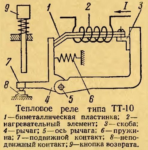
Thermal relay, the device of which consists of the simplest elements:
- thermosensitive element.
- Contact with self-return.
- Contacts.
- Spring.
- Bimetallic conductor in the form of a plate.
- Button.
- Setpoint current regulator.
The temperature sensitive element is a temperature sensor used to transfer heat to a bimetallic plate or other thermal protection element. Contact with self-return allows, when heated, to instantly open the power supply circuit of an electrical consumer to avoid overheating.
The plate consists of two types of metal (bimetal), and one of them has a high thermal expansion coefficient (Kp). They are fastened together by welding or rolling at high temperatures. When heated, the thermal protection plate bends towards the material with a lower Kp, and after cooling, the plate takes its original position. Basically, the plates are made of invar (lower value of Kp) and non-magnetic or chromium-nickel steel (higher Kp).
The button turns on the TR, the setting current regulator is necessary to set the optimal value of I for the consumer, and its excess will lead to the operation of the TR.
The operating principle of TR is based on the Joule-Lenz law. The current is the directed movement of charged particles that collide with the atoms of the crystal lattice of the conductor (this value is the resistance and is denoted by R). This interaction causes the appearance of thermal energy obtained from electrical energy. The dependence of the duration of the flow on the temperature of the conductor is determined by the Joule-Lenz law.
The formulation of this law is as follows: when I passes through the conductor, the amount of heat Q generated by the current, when interacting with the atoms of the crystal lattice of the conductor, is directly proportional to the square of I, the value of R of the conductor and the time the current acts on the conductor. Mathematically, it can be written as follows: Q = a * I * I * R * t, where a is the conversion factor, I is the current flowing through the desired conductor, R is the resistance value and t is the flow time of I.
When the coefficient a = 1, the calculation result is measured in joules, and provided that a = 0.24, the result is measured in calories.
Bimetallic material is heated in two ways. In the first case, I passes through the bimetal, and in the second, through the winding. Winding insulation slows down the flow of thermal energy. The thermal switch heats up more at high values of I than when it comes into contact with the temperature sensing element. The contact actuation signal is delayed. Both principles are used in modern TR models.
The heating of the bimetal plate of the thermal protection device is carried out when the load is connected. Combined heating allows you to get a device with optimal characteristics. The plate is heated by the heat generated by I when passing through it, and by a special heater when I is loaded. During heating, the bimetallic strip deforms and acts on the contact with self-return.
 Watch this video on YouTube
What is important to know?
In order not to be repeated, and not to pile up unnecessary text, I will briefly outline the meaning. The current relay is an obligatory attribute of the electric drive control system.This device responds to the current that passes through it to the motor. It does not protect the electric motor from a short circuit, but only protects it from working with increased current that occurs during overload or abnormal operation of the mechanism (for example, a wedge, jamming, rubbing, and other unforeseen moments).


When choosing a thermal relay, they are guided by the passport data of the electric motor, which can be taken from the plate on its body, as in the photo below:
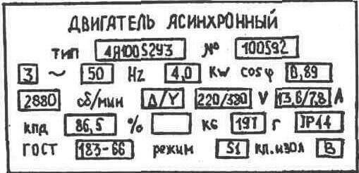 As you can see on the tag, the rated current of the electric motor is 13.6 / 7.8 Amps, for voltages of 220 and 380 Volts. According to the operating rules, the thermal relay must be selected 10-20% more than the nominal parameter. The ability of the heating unit to work in time and prevent damage to the electric drive depends on the correct choice of this criterion. When calculating the installation current for the nominal value given on the tag at 7.8 A, we got the result of 9.4 Amperes for the current setting of the device.
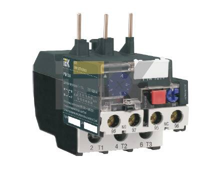
When choosing in the product catalog, you need to take into account that this value was not the extreme one on the setpoint adjustment scale, so it is advisable to choose a value closer to the center of the adjustable parameters. For example, as on the RTI-1314 relay:
The principle of operation of the thermal relay
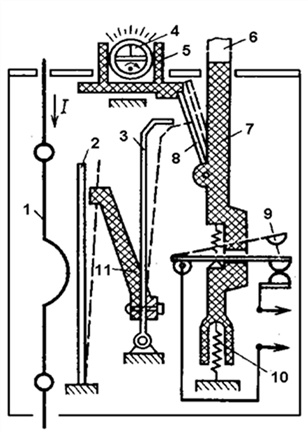
To date, thermal relays have become the most popular, whose action is based on the use of the properties of bimetallic plates. For the manufacture of bimetallic plates in such relays, as a rule, Invar and chromium-nickel steel are used. The plates themselves are firmly connected to each other by welding or rolling.Since one of the plates has a large coefficient of expansion when heated, and the other has a smaller one, if they are exposed to high temperature (for example, when current passes through a metal), the plate bends in the direction where the material with a lower coefficient of expansion is located.
Thus, at a certain level of heating, the bimetallic plate bends and affects the system of relay contacts, which leads to its operation and opening of the electrical circuit. It should also be noted that as a result of the low rate of the plate deflection process, it cannot effectively extinguish the arc that occurs in the event of an electrical circuit opening. In order to solve this problem, it is necessary to accelerate the impact of the plate on the contact. That is why most modern relays also have accelerating devices that allow you to effectively break the circuit in the shortest possible time.
Connecting, adjusting and marking TP
It is necessary to install an electrothermal relay with a magnetic starter that connects and starts the engine. As an independent device, the device is placed on a DIN rail or mounting plate.
Device connection diagram
Connection diagrams for starters with thermal types of relays depend on the type of device:
- Series connection with motor winding or starter coil to a normally open contact (NC). The element works if it is connected to the stop key. The system is used when it is necessary to equip the engine with an alarm protection. The relay is placed after the starting contactors, but before the motor, then the NC contact is connected.
- Starter zero break by normally closed contact.The circuit is convenient and practical - zero can be connected to the TR contact, a jumper is thrown from the second contact to the starter coil. At the moment the relay is activated, there is a break in zero and a de-energization of the starter.
- Reverse scheme. The control circuit contains a normally closed and three power contacts. The electric motor is powered through the latter. When the protective mode is activated, the starter is de-energized and the motor stops.
Adjustment procedure
The device is set up on specialized stands with a low-power load transformer. Heating nodes are connected to its secondary mechanisms, and the voltage is controlled using an autotransformer. The current limit of the load is adjusted by an ammeter connected through the secondary circuit.
The check is done like this:
- Turning the transformer handle to zero position with voltage applied. Then the load current is selected with the knob and the relay operation time is checked from the moment the lamp goes out with a stopwatch. The norm is 140-150 seconds at a current of 1.5 A.
- Setting the current rating. Produced when the current rating of the heater does not match the rating of the motor. Adjustment limit - 0.75 - 1.25 of the heater rating.
- Current setting setting.
For the last step, you need to calculate:
- determine the correction for the rated current without temperature compensation using the formula ±E1 = (Inom-Io)/СIo. Io - zero setting current, C - division value of the eccentric (C \u003d 0.05 for open models and C \u003d 0.055 - for closed ones);
- calculate the correction taking into account the ambient temperature E2=(t - 30)/10, where t is the temperature;
- calculate the total correction by adding the obtained values;
- round the result up or down, translate the eccentric.
Manual adjustment
You can manually adjust the thermal relay. The value of the trip current can be set in the range from 20 to 30% of the nominal value. The user will need to smoothly move the lever to change the bending of the bimetal plate. The trip current is also adjustable after replacement of the thermal assembly.
Modern switches are equipped with a test button to search for a breakdown without using the stand. Using the reset key, you can reset the settings in automatic or manual mode. An indicator is used to track the status of the device.
Choice of electrothermal relay
The choice of a thermal relay depends on many factors of its operation: ambient temperature; where it is installed; power of the connected equipment; necessary means of emergency notification and so on. Most often, the consumer makes a choice based on the following technical characteristics of the device.
- For single-phase networks, you should choose a thermal relay with the function of auto-reset and return contacts to their original state after a certain period of time. Such a device will re-trigger if the alarm situation persists and the current overload of the equipment continues to be present.
- For hot climates and hot workshops, thermal relays with an air temperature compensator should be used. These include models with the designation TRV. They are able to function normally in a wide range of external temperatures.
- For equipment critical to phase failure, appropriate thermal protection should be used. Almost all thermal relay models are able to turn off electrical installations in the event of such a situation, since a break in one phase sharply increases the load current on the remaining two.
- Thermal relays with light indication are most often used in industry, where it is necessary to quickly respond to an emergency. Device status LEDs allow the operator to visually monitor the workflow.
The price of a thermal protection relay can fluctuate over a very wide range. The cost of the device depends on many factors: general technical characteristics, the presence of additional functions used in the production of materials, as well as the popularity of the device manufacturer. The minimum price of a thermal relay is about 500 rubles, and the maximum can reach several thousand. Relays from well-known manufacturers, without fail, are completed with a passport with a detailed description of technical characteristics, as well as complete instructions for connecting the device to electrical installations.
What is a relay and where are they used?
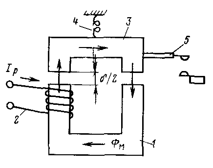
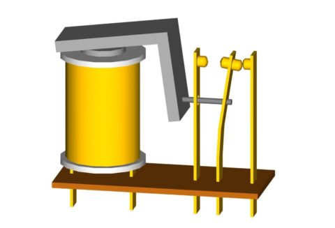
An electromagnetic relay is a high-precision and reliable switching device, the principle of which is based on the influence of an electromagnetic field. It has a simple structure, represented by the following elements:
- coil;
- anchor;
- fixed contacts.
The electromagnetic coil is fixed motionless on the base, inside it is a ferromagnetic core, a spring-loaded armature is attached to the yoke to return to its normal position when the relay is de-energized.
Simply put, the relay provides opening and closing of the electrical circuit in accordance with incoming commands.
Electromagnetic relays are reliable in operation, which is why they are used in various industrial and household electrical appliances and equipment.
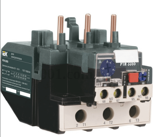
The device and operation of the electrothermal relay.
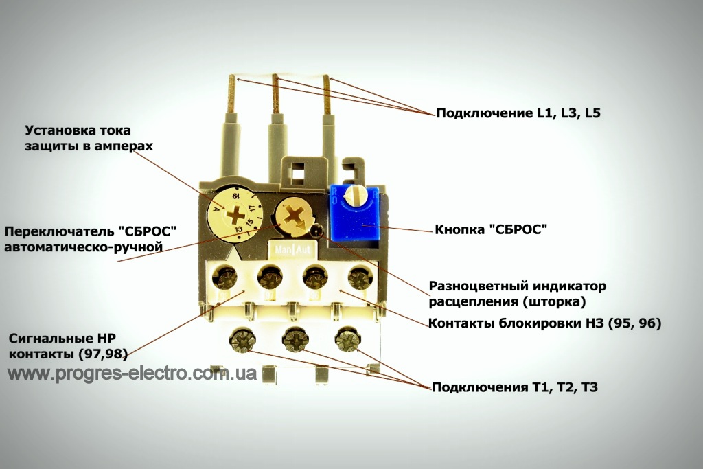
The electrothermal relay works complete with a magnetic starter. With its copper pin contacts, the relay is connected to the output power contacts of the starter. The electric motor, respectively, is connected to the output contacts of the electrothermal relay.

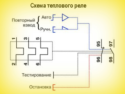
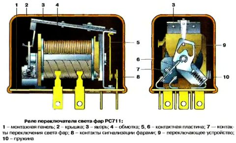
Inside the thermal relay there are three bimetallic plates, each of which is welded from two metals with a different coefficient of thermal expansion. The plates through a common "rocker" interact with the mechanism of the mobile system, which is connected with additional contacts involved in the motor protection circuit:
1. Normally closed NC (95 - 96) are used in starter control circuits;
2. Normally open NO (97 - 98) are used in signaling circuits.
The principle of operation of the thermal relay is based on deformations bimetallic plate when it is heated by a passing current.
Under the influence of the flowing current, the bimetallic plate heats up and bends towards the metal, which has a lower coefficient of thermal expansion. The more current flows through the plate, the more it will heat up and bend, the faster the protection will work and turn off the load.
Assume that the motor is connected via a thermal relay and is operating normally. At the first moment of operation of the electric motor, the rated load current flows through the plates and they heat up to the operating temperature, which does not cause them to bend.
For some reason, the load current of the electric motor began to increase and a current flowing through the plates exceeded the nominal one. The plates will begin to heat up and bend more strongly, which will set in motion the mobile system and it, acting on the additional relay contacts (95 – 96), will de-energize the magnetic starter. As the plates cool down, they will return to their original position and the relay contacts (95 – 96) will close. The magnetic starter will again be ready to start the electric motor.
Depending on the amount of current flowing in the relay, a current trip setting is provided, which affects the plate bending force and is regulated by a rotary knob located on the relay control panel.
In addition to the rotary control on the control panel there is a button "TEST”, designed to simulate the operation of the relay protection and check its performance before being included in the circuit.
«Indicator» informs about the current state of the relay.
Button "STOP» the magnetic starter is de-energized, but as in the case of the «TEST» button, the contacts (97 – 98) do not close, but remain in the open state. And when you use these contacts in the signaling circuit, then consider this moment.
The electrothermal relay can work in manual or automatic mode (default is automatic).
To switch to manual mode, turn the rotary button "RESET» counterclockwise, while the button is slightly raised.
Suppose that the relay has worked and de-energized the starter with its contacts.
When operating in automatic mode, after the bimetallic plates have cooled down, the contacts (95 — 96) and (97 — 98) will automatically go to the initial position, while in manual mode, the transfer of contacts to the initial position is carried out by pressing the button "RESET».
In addition to email protection. motor from overcurrent, the relay provides protection in the event of a power phase failure. For example.If one of the phases breaks, the electric motor, working on the remaining two phases, will consume more current, which will cause the bimetallic plates to heat up and the relay will work.
However, the electrothermal relay is not able to protect the motor from short-circuit currents and itself needs to be protected from such currents. Therefore, when installing thermal relays, it is necessary to install automatic switches in the power supply circuit of the electric motor that protect them from short circuit currents.
When choosing a relay, pay attention to the rated load current of the motor, which will protect the relay. In the instruction manual that comes in the box, there is a table according to which a thermal relay is selected for a specific load: For example, the RTI-1302 relay has a setting current adjustment limit from 0.16 to 0.25 Amperes
This means that the load for the relay should be selected with a rated current of about 0.2 A or 200 mA
For example, the RTI-1302 relay has a setting current adjustment limit from 0.16 to 0.25 Amperes. This means that the load for the relay should be selected with a rated current of about 0.2 A or 200 mA.


Relay characteristics

When choosing a TR, it is necessary to be guided by its characteristics. Claims may include:
- rated current;
- operating current adjustment spread;
- network voltage;
- type and number of contacts;
- rated power of the connected device;
- minimum threshold;
- device class;
- phase shift response.
The rated current of the TP must correspond to that indicated on the motor to which the connection will be made. You can find out the value for the motor on the nameplate, which is located on the cover or on the housing. The mains voltage must strictly correspond to the one where it will be used. It can be 220 or 380/400 volts.The number and type of contacts also matter, as different contactors have different connections. The TR must be able to withstand the power of the motor so that false tripping does not occur. For three-phase motors, it is better to take TR, which provide additional protection in case of phase imbalance.


