- Design of thermal relays
- Principle of operation
- What to do if the passport details are not known?
- Nuances when installing the device
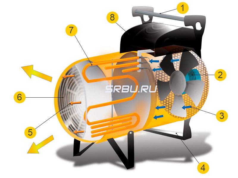
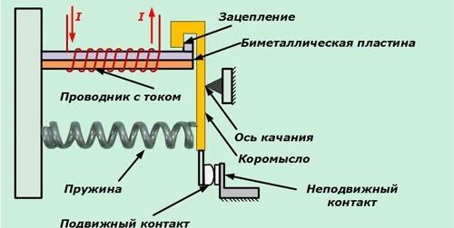
- The device and operation of the electrothermal relay.
- The principle of operation of the thermal relay
- How to choose an electric motor: conditions
- Choosing a thermostat for underfloor heating
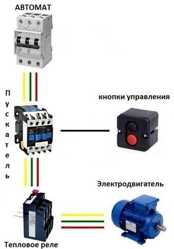
- Installation scheme
- Manufacturers overview
- What causes an electric motor to fail?
- Thermal protection of a weak motor
- Main characteristics
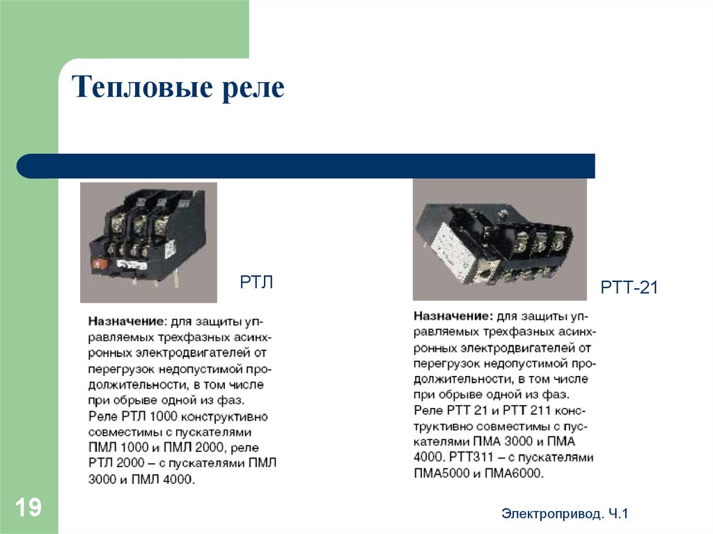
Design of thermal relays
Thermal relays of all types have a similar device. The most important element of any of them is a sensitive bimetallic plate.
The value of the tripping current is influenced by the temperature indicators of the environment in which the relay operates. An increase in temperature reduces the response time.
In order to minimize this influence, device developers choose the highest bimetal temperature possible. For the same purpose, some relays are equipped with an additional compensation plate.
The device consists of a body (1), a bimetallic plate (2), a pusher (3), an actuating plate (4), a spring (5), an adjusting screw (6), a compensator plate (7), contacts (8), an eccentric (9 ), back buttons (10)
If nichrome heaters are included in the relay design, they are connected in parallel, series or parallel-series circuit with a plate.
The value of the current in the bimetal is regulated using shunts. All parts are built into the body. The bimetallic U-shaped element is fixed on the axis.
The coil spring rests against one end of the plate. At the other end, it is based on a balanced insulating block. It rotates around an axis and is a support for a contact bridge equipped with silver contacts.
To coordinate the setting current, the bimetallic plate is connected to its mechanism with its left end. Adjustment occurs due to the influence on the primary deformation of the plate.
If the magnitude of the overload currents becomes equal to or greater than the settings, the insulating block turns under the influence of the plate. During its tipping over, the opening contact of the device is switched off.
TRT fixture in section. Here the main elements are: housing (1), setting mechanism (2), button (3), axle (4), silver contacts (5), contact bridge (6), insulating block (7), spring (8), plate bimetallic (9), axle (10)
The relay automatically returns to its original position. The self-return process takes no more than 3 minutes from the moment the protection is turned on. Manual reset is also possible, for this a special Reset key is provided.
When using it, the device takes its original position in 1 minute. To activate the button, it is turned counterclockwise until it rises above the body. The setting current is usually indicated on the label.
Principle of operation
You learned what a thermal relay looks like, now let's go ahead and tell you how this device works. As we said earlier, RT protects the motor from prolonged overload.
Each motor has a rating plate with the rated operating current. There are mechanisms in the operation of which it is possible to exceed the operating current, both during start-up and during the work process. With prolonged exposure to such overloads, the windings overheat, the insulation is destroyed, and the motor itself fails.
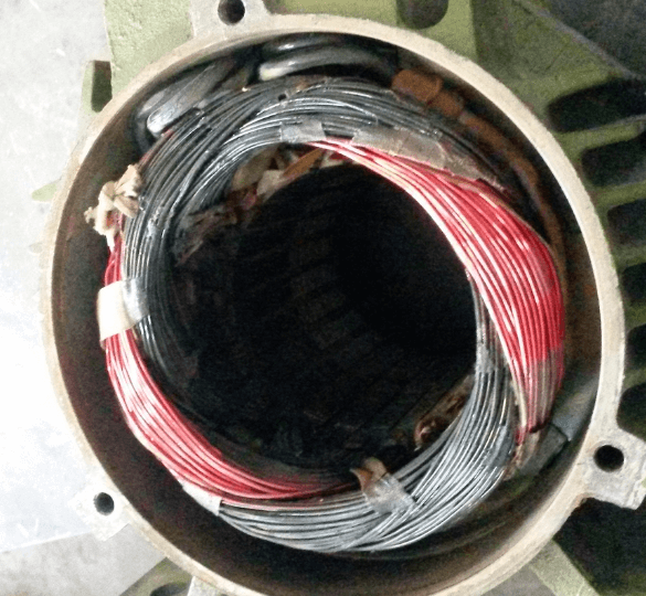
This thermal protection relay is designed to act on control circuits by shutting down the circuit, opening contacts, or giving a warning signal to duty personnel by closing contacts. The device is installed after the starting contactor in the power circuit before the electric motor in order to control the passing current.
The parameters are set up from the rated current of the motor, by 10-20%, according to the passport data. The machine does not turn off immediately, but after a certain time. It all depends on the ambient temperature and the overload current, and can vary from 5 to 20 minutes. An incorrectly selected parameter will lead to false operation or ignoring of overload and failure of the equipment.
Graphic designation of the device on the diagram according to GOST:
You can learn more about how a thermal relay works and how it works by watching this video:
The device and principle of operation of the PTT
What to do if the passport details are not known?
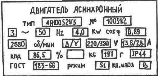
For this case, we recommend using a current clamp or a C266 multimeter, the design of which also includes a current clamp.Using these devices, you need to determine the motor current in operation by measuring it in phases.
In the case when data is partially read on the table, we place a table with passport data of asynchronous motors widely used in the national economy (AIR type). With it, it is possible to determine In.

By the way, we recently examined the principle of operation and the device of thermal relays, which we strongly recommend that you familiarize yourself with!
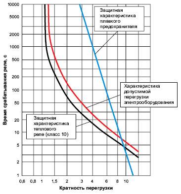
Depending on the current load, the protection response time will also differ, at 125% it should be about 20 minutes. The diagram below shows the vector curve of the current ratio versus In and the operating time.
Finally, we recommend watching a useful video on the topic:


We hope that after reading our article, it became clear to you how to choose a thermal relay for the motor according to the rated current, as well as the power of the electric motor itself. As you can see, the conditions for choosing a device are not difficult, because. without formulas and complex calculations, you can choose the appropriate denomination using the table!
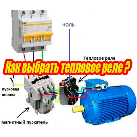
In a circuit with a thermal relay, a normally-closed relay contact is used. QC1.1 in the starter control circuit, and three power contacts KK1through which power is supplied to the motor.
When the circuit breaker is turned on QF1 phase "BUT”, feeding the control circuits, through the button SB1 "Stop" goes to contact No. 3 of the button SB2 Start, auxiliary contact 13NO starter KM1, and remains on duty at these contacts. The circuit is ready to go.
By pressing the button SB2 phase via normally closed contact QC1.1 enters the coil of the magnetic starter KM1, the starter operates and its normally open contacts are closed, and normally closed contacts are opened.
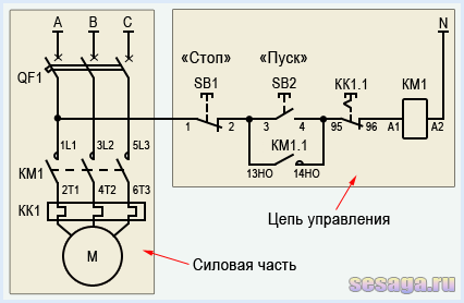
When the contact is closed KM1.1 the starter gets up on self-pickup. When closing power contacts KM1 phase "BUT», «AT», «FROM» through thermal relay contacts KK1 enter the motor windings and the motor starts rotating.
With an increase in the load current through the power contacts of the thermal relay KK1, the relay will operate, contact QC1.1 open and starter KM1 de-energized.
If it becomes necessary to simply stop the engine, it will be enough to press the button "Stop". The button contacts will break, the phase will be interrupted and the starter will be de-energized.
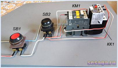
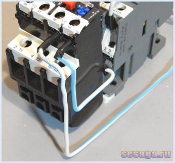
The photographs below show part of the wiring diagram of the control circuits:
The following circuit diagram is similar to the first one and differs only in that the normally closed contact of the thermal relay (95 – 96) breaks the zero of the starter. It is this scheme that has become most widespread due to the convenience and economy of installation: zero is immediately brought to the contact of the thermal relay, and a jumper is thrown from the second contact of the relay to the starter coil.

When the thermostat is triggered, the contact QC1.1 opens, "zero" breaks and the starter is de-energized.
And in conclusion, consider the connection of an electrothermal relay in a reversible starter control circuit.
It, like the circuit with one starter, differs from the typical circuit only in the presence of a normally-closed relay contact QC1.1 in the control circuit, and three power contacts KK1through which the motor is powered.
When the protection is triggered, the contacts QC1.1 break and turn off "zero". A running starter is de-energized and the motor stops. If it becomes necessary to simply stop the engine, just press the button "Stop».
So the story about the magnetic starter came to its logical conclusion.
It is clear that theoretical knowledge alone is not enough. But if you practice, you can assemble any circuit using a magnetic starter.
And already, according to the established tradition, a short video about the use of an electrothermal relay.
Nuances when installing the device
The response speed of the thermal module can be affected not only by current overloads, but also by external temperature indicators. Protection will work even in the absence of overloads.
It also happens that under the influence of forced ventilation, the motor is subject to thermal overload, but the protection does not work.
To avoid such phenomena, you need to follow the recommendations of experts:
- When choosing a relay, focus on the maximum allowable response temperature.
- Mount the protection in the same room as the object to be protected.
- For installation, choose a place where there are no heat sources or ventilation devices.
- It is necessary to adjust the thermal module, focusing on the actual ambient temperature.
- The best option is the presence of built-in thermal compensation in the design of the relay.
An additional option of the thermal relay is protection in the event of a phase failure or a full supply network. For three-phase motors, this moment is especially relevant.
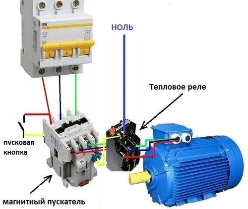
 The current in the thermal relay moves in series through its heating module and on to the motor. The device is connected to the starter winding by additional contacts (+)
In the event of a failure in one phase, the other two take on a larger current. As a result, overheating occurs quickly, and then shutdown. If the relay is inefficient, both the motor and the wiring can fail.
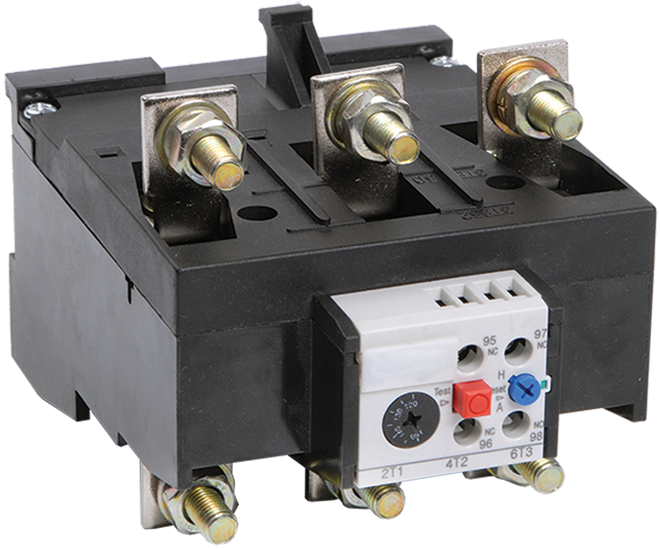
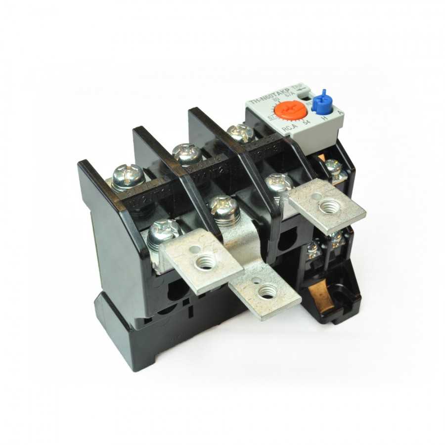
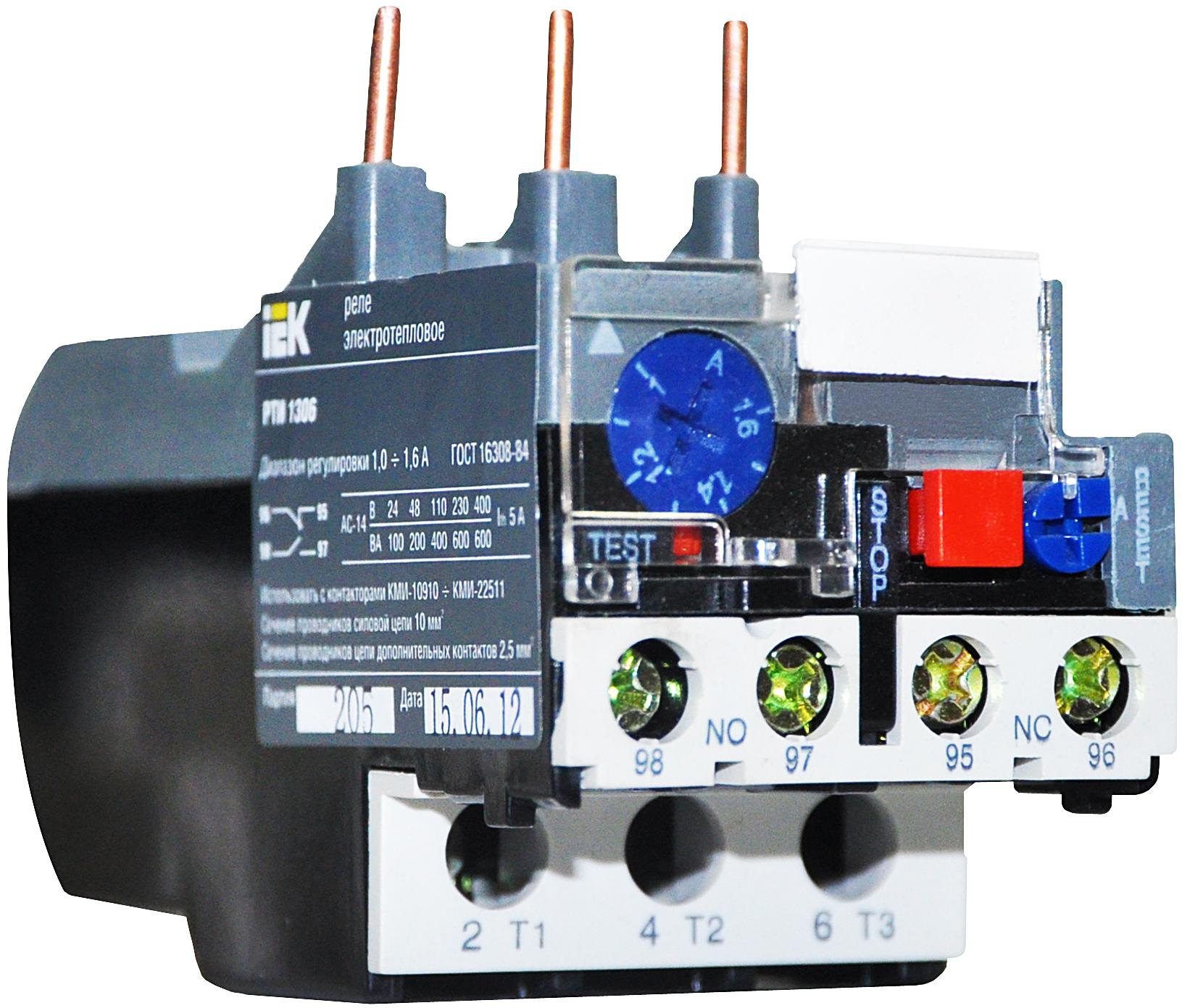
The device and operation of the electrothermal relay.
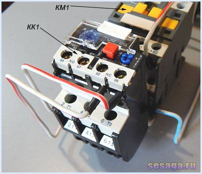
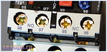
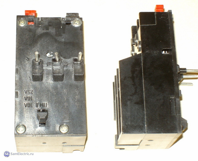
The electrothermal relay works complete with a magnetic starter. With its copper pin contacts, the relay is connected to the output power contacts of the starter. The electric motor, respectively, is connected to the output contacts of the electrothermal relay.


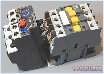
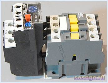
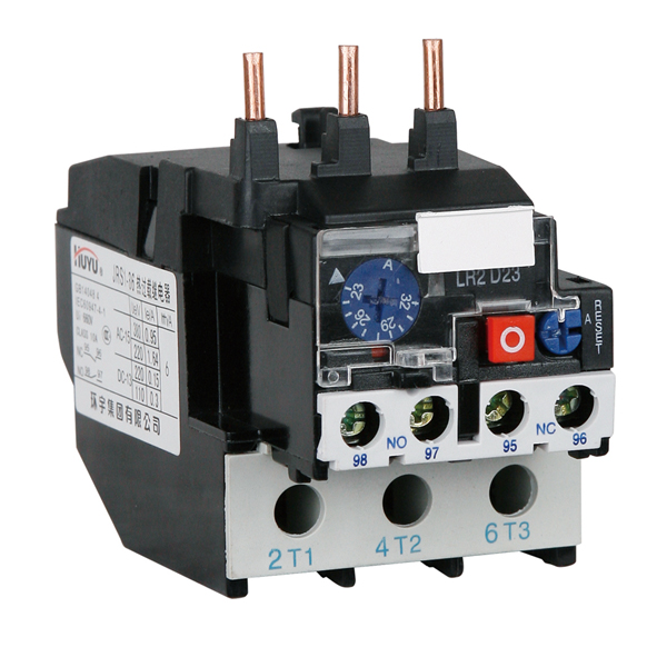
Inside the thermal relay there are three bimetallic plates, each of which is welded from two metals with a different coefficient of thermal expansion. The plates through a common "rocker" interact with the mechanism of the mobile system, which is connected with additional contacts involved in the motor protection circuit:
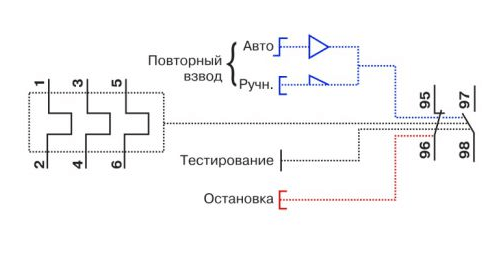
1. Normally closed NC (95 - 96) are used in starter control circuits;
2. Normally open NO (97 - 98) are used in signaling circuits.
The principle of operation of the thermal relay is based on deformations bimetallic plate when it is heated by a passing current.
Under the influence of the flowing current, the bimetallic plate heats up and bends towards the metal, which has a lower coefficient of thermal expansion. The more current flows through the plate, the more it will heat up and bend, the faster the protection will work and turn off the load.
Assume that the motor is connected via a thermal relay and is operating normally. At the first moment of operation of the electric motor, the rated load current flows through the plates and they heat up to the operating temperature, which does not cause them to bend.
For some reason, the load current of the electric motor began to increase and a current flowing through the plates exceeded the nominal one. The plates will begin to heat up and bend more strongly, which will set in motion the mobile system and it, acting on the additional relay contacts (95 – 96), will de-energize the magnetic starter.As the plates cool down, they will return to their original position and the relay contacts (95 – 96) will close. The magnetic starter will again be ready to start the electric motor.
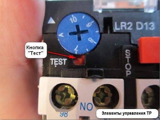
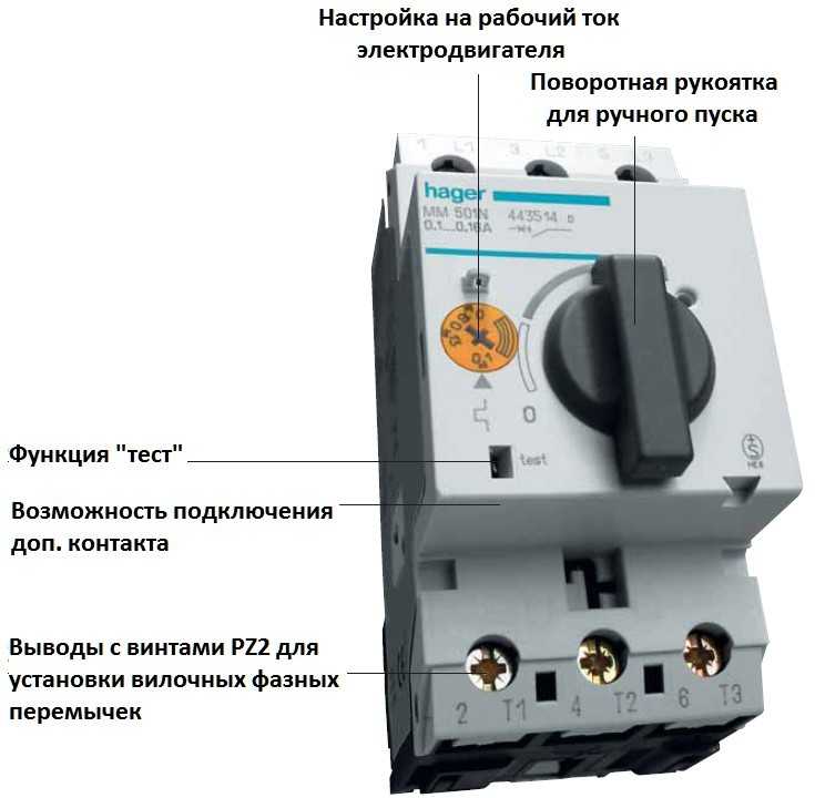
Depending on the amount of current flowing in the relay, a current trip setting is provided, which affects the plate bending force and is regulated by a rotary knob located on the relay control panel.
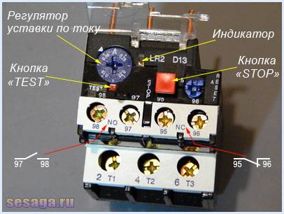
In addition to the rotary control on the control panel there is a button "TEST”, designed to simulate the operation of the relay protection and check its performance before being included in the circuit.
«Indicator» informs about the current state of the relay.
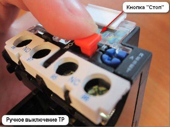
Button "STOP» the magnetic starter is de-energized, but as in the case of the «TEST» button, the contacts (97 – 98) do not close, but remain in the open state. And when you use these contacts in the signaling circuit, then consider this moment.
The electrothermal relay can work in manual or automatic mode (default is automatic).
To switch to manual mode, turn the rotary button "RESET» counterclockwise, while the button is slightly raised.
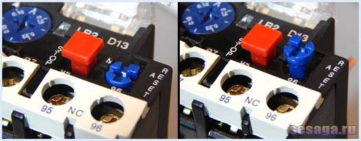
Suppose that the relay has worked and de-energized the starter with its contacts.
When operating in automatic mode, after the bimetallic plates have cooled down, the contacts (95 — 96) and (97 — 98) will automatically go to the initial position, while in manual mode, the transfer of contacts to the initial position is carried out by pressing the button "RESET».
In addition to email protection. motor from overcurrent, the relay provides protection in the event of a power phase failure. For example.If one of the phases breaks, the electric motor, working on the remaining two phases, will consume more current, which will cause the bimetallic plates to heat up and the relay will work.
However, the electrothermal relay is not able to protect the motor from short-circuit currents and itself needs to be protected from such currents. Therefore, when installing thermal relays, it is necessary to install automatic switches in the power supply circuit of the electric motor that protect them from short circuit currents.
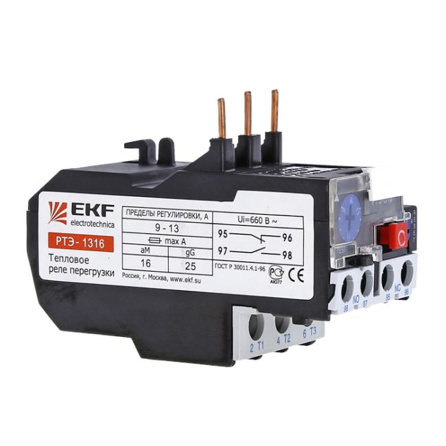
When choosing a relay, pay attention to the rated load current of the motor, which will protect the relay. In the instruction manual that comes in the box, there is a table according to which a thermal relay is selected for a specific load:
For example, the RTI-1302 relay has a setting current adjustment limit from 0.16 to 0.25 Amperes. This means that the load for the relay should be selected with a rated current of about 0.2 A or 200 mA.
The principle of operation of the thermal relay
In some cases, a thermal relay may be built into the motor windings. But most often it is used in tandem with a magnetic starter. This makes it possible to extend the life of the thermal relay. The entire starting load falls on the contactor. In this case, the thermal module has copper contacts that are connected directly to the starter's power inputs. Conductors from the engine are brought to the thermal relay. Simply put, it is an intermediate link that analyzes the current passing through it from the starter to the motor.
The thermal module is based on bimetallic plates. This means that they are made from two different metals. Each of them has its own coefficient of expansion when exposed to temperature.The plates through the adapter act on the movable mechanism, which is connected to the contacts that go to the electric motor. In this case, the contacts can be in two positions:
- normally closed;
- normally open.
The first type is suitable for motor starter control, and the second type is used for alarm systems. The thermal relay is built on the principle of thermal deformation of bimetallic plates. As soon as current begins to flow through them, their temperature begins to rise. The more current flows, the higher the temperature of the plates of the thermal module rises. In this case, the plates of the thermal module are shifted towards the metal with a lower coefficient of thermal expansion. In this case, the contacts close or open and the engine stops.
It is important to understand that the thermal relay plates are designed for a certain rated current. This means that heating to a certain temperature will not cause deformation of the plates.
If, due to an increase in the load on the engine, the thermal module tripped and turned off, then after a certain period of time, the plates return to their natural position and the contacts close or open again, giving a signal to the starter or other device. In some types of relays, an adjustment is available for the amount of current that must flow through it. To do this, a separate lever is taken out, with which you can select the value on the scale.


In addition to the current regulator, there may also be a button labeled Test on the surface. It allows you to check the thermal relay for operability. It must be pressed while the engine is running.If this stops, then everything is connected and functioning correctly. Under a small Plexiglas plate, there is a status indicator for the thermal relay. If this is a mechanical option, then you can see a strip of two colors in it, depending on the ongoing processes. On the body next to the current regulator is the Stop button. It, unlike the Test button, turns off the magnetic starter, but contacts 97 and 98 remain open, which means that the alarm does not work.
Note! The description is given for the thermal relay LR2 D1314. Other options have a similar structure and connection scheme.
The thermal relay can operate in manual and automatic mode.
A second one is installed from the factory, which is important to consider when connecting. To switch to manual control, you must use the Reset button
It must be turned counterclockwise so that it rises above the body. The difference between the modes is that in the automatic mode, after the protection is triggered, the relay will return to its normal state after the contacts have completely cooled down. In manual mode, this can be done using the Reset key. It almost instantly returns the pads to their normal position.
The thermal relay also has additional functionality that protects the motor not only from current overloads, but also when the mains or phase is disconnected or broken. This is especially true for three-phase motors. It happens that one phase burns out or other problems occur with it. In this case, the metal plates of the relay, to which the other two phases enter, begin to pass more current through themselves, which leads to overheating and shutdown.This is necessary to protect the two remaining phases as well as the motor. In the worst case scenario, such a scenario can lead to the failure of the engine, as well as the lead wires.
Note! The thermal relay is not designed to protect the motor from a short circuit. This is due to the high breakdown rate
The plates just don't have time to react. For these purposes, it is necessary to provide special circuit breakers, which are also included in the power circuit.
How to choose an electric motor: conditions
At present, the use of electric motors is quite widespread. These devices are used in various equipment (ventilation systems, pumping stations or electric vehicles). For each type of machine, you need the right choice and tuning of engines.
Criterias of choice:
- Type of current;
- Device power;
- Job.
According to the type of electric current, electric motors are divided into devices operating on alternating and direct current.
It is worth noting that DC motors have proven themselves from the best side, but due to the need to install additional equipment to ensure their operation, additional financial costs are also required.
AC motors are widely used. They are divided into two types (synchronous and asynchronous).
Synchronous devices are used for equipment in which constant rotation is important (generators and compressors). Different characteristics of synchronous motors also differ
For example, the rotation speed varies from 120 to 1000 rpm. The power of the devices reaches 10 kW.
In industry, the use of asynchronous motors is common.It is worth noting that these devices have higher rotation rates. For their manufacture, aluminum is mainly used, which makes it possible to manufacture lightweight rotors.
Based on the fact that during operation the engine produces a constant rotation of various devices, it is necessary to correctly select its power. It is worth noting that for various devices, there is a special formula according to which the choice is made.
The determining factor in the load on the engines is the mode of operation. Therefore, the choice of device is made according to this characteristic. There are several modes of operation that are marked (S1 - S9). Each of the nine modes is suitable for a specific engine operation.
Choosing a thermostat for underfloor heating
For the normal operation of underfloor heating, the installation of a thermal relay is required - a thermostat, with which you can significantly reduce heating costs. The device here is required only to turn the heating on and off at a certain time interval or after a signal from a thermometer.
When choosing a thermostat, first of all, its power should be taken into account, which should be identical to the power of the warm field.
Also, for certain types of underfloor heating, it is necessary to select the type of thermal relay, which are divided into several groups:
- devices designed only to provide an economical mode, allowing to reduce energy consumption;
- devices with a customizable timer, with the help of which time periods are set during which the room will be heated with a certain intensity;
- devices that can be programmed for complex operating procedures, alternating periods of operation in economy mode and maximum heating;
- relay, which has a built-in limiter that prevents excessive heating of the floor covering and the heating element.
The selection of a thermostat for a particular room is carried out depending on its area. For a small room, an ordinary device without complex settings and programming is more suitable. Installation of more complex devices is necessary for spacious rooms. In such rooms, electronic relays are most often installed, equipped with temperature sensors installed in the thickness of the floor.
Installation scheme
When arranging underfloor heating, it is recommended to mount a thermal relay in the immediate vicinity of sockets at a distance of 0.6-1.0 m from the floor. Before starting work, the home electrical network should be turned off.


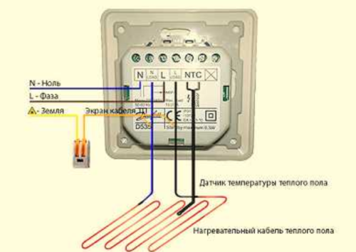 circuit diagram thermal relay connection when laying underfloor heating
The installation of the thermal regulator should begin with connecting the power wires to the mounting box. Then, between the relay and the heater, you need to install and connect a temperature sensor that fits into the corrugated pipe.
The relay itself is located in the mounting box. If there are interferences in the form of corrugations, they should be eliminated. The thermostat must be placed strictly horizontally in level. The control panel is placed in its permanent place and fastened with screws.
Manufacturers overview
For underfloor heating, many models of thermostats are available. Some of the most popular models are presented in the table.
| Model | Manufacturer | Characteristics | Approximate cost, rub. |
| TR 721 | "Special Systems and Technologies" Russia | Maximum load current 16 A Power consumption 450 mW | 4800 |
| AT10F | Salus Poland | Temperature range 30-90 Setting accuracy 1 Voltage 230 VAC 10(5) A | 1750 |
| BMT-1 | Ballu | Temperature range 10 - 30 °C Maximum current 16 A | 1150 |
What causes an electric motor to fail?
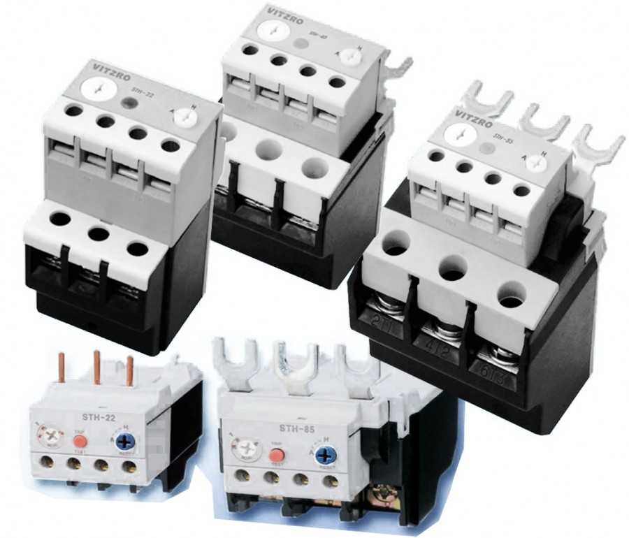
You can see the photo of various types of motor protection to get an idea of how it looks.
Consider cases of failure of electric motors in which serious damage can be avoided with the help of protection:
- Insufficient level of electrical supply;
- High level of voltage supply;
- Rapid change in the frequency of current supply;
- Improper installation of the electric motor or storage of its main elements;
- Increase in temperature and exceeding the permissible value;
- Insufficient cooling supply;
- Elevated ambient temperature;
- Reduced barometric pressure if the engine is operated at elevated altitude based on sea level;
- Increased temperature of the working fluid;
- Unacceptable viscosity of the working fluid;
- The engine often turns off and on;
- Rotor blocking;
- Unexpected phase break.


A fusible version of the fuse is often used for this, as it is simple and capable of many functions:
The fuse-switch version is represented by an emergency switch and a fuse connected on the basis of a common housing. The switch allows you to open or close the network using a mechanical method, and the fuse creates high-quality motor protection based on the effects of electric current.However, the switch is used mainly for the service process, when it is necessary to stop the transfer of current.

Fused versions of fuses based on fast acting are considered excellent short circuit protectors. But short overloads can lead to breakage of fuses of this type. Because of this, it is recommended to use them on the basis of the effect of a negligible transient voltage.

Fuses based on delay trip are able to protect against overload or various short circuits. Typically, they are able to withstand a 5-fold increase in voltage for 10-15 seconds.
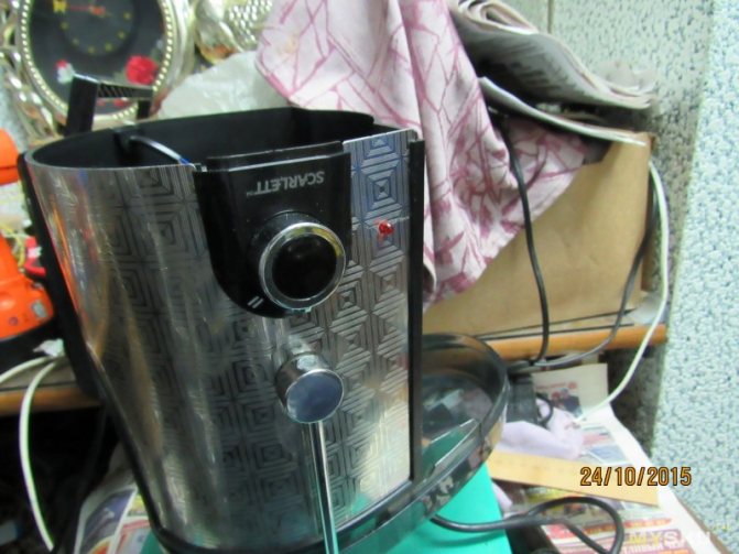
Thermal protection of a weak motor
Background of the issue. My recently bought juicer was almost on the verge of death, due to the pulp of the pear, it only slowed down a little. How much I listened to my address. But am I to blame? The manufacturer, reducing the cost of products, does not do any protection for the weak electric motor of the product. To prevent this situation from happening again, you need to protect this engine. As an option, there are 2 types of protection: - current (when a current sensor is connected to the circuit and the flowing current is controlled through it), in critical modes the current increases; -thermal (temperature is controlled). Additional Information
The principle of operation of thermal relays is based on the thermal effect of a current heating a bimetallic plate consisting of two metal strips connected by flat surfaces with different coefficients of linear expansion. When the temperature changes, due to the different linear expansion of the parts, the plate bends.When heated to a certain temperature, the plate presses on the release latch and, under the action of the spring, a quick electrical disconnection of the contacts occurs.
Decided to go with thermal protection. Fumbling on Aliexpress, I found the following products: 1. thermal switch
link
/item/AC-125V-250V-5A-Air-Compressor-Circuit-Breaker-Overload-Protector-Protection-DC-12V-24V-32V-50V/32295157899.html
2.thermal switch
link
/item/5Pcs-lot-40C-Degree-Celsius-104F-NO-Normal-Open-Thermostat-Thermal-Protector-Thermostat-temperature-control-switch/32369022941.html


3.thermal switch
link
According to point 1, friends from China sent as many as 10A instead of 5A. But it was decided to try it anyway.
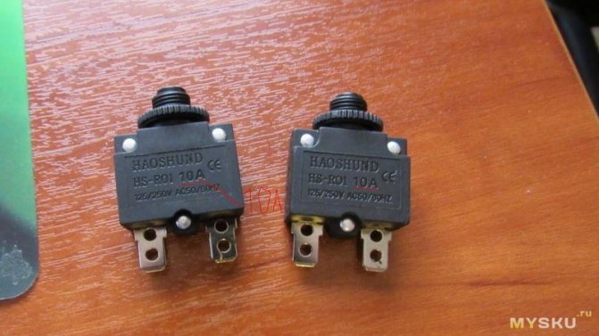
Having loaded the Chinese product with a 17A load, we waited for the protection to finally work, but the laboratory circuit breaker almost worked and after 20 seconds the experiment was completed. After winning the dispute, the thing was dismantled. Well, what can I say 2 bimetallic plates, probably everything is quite efficient, it only took enough time.
Let's move on to points 2 and 3.
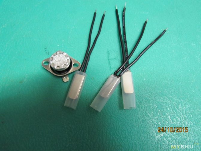
A test with a megger at 1000v showed that the insulation is excellent over 2000MΩ. To check for drawdown, I stock up pots of water. Water boils at normal pressure at 100 degrees. We need to check 95.85 and 80. Thermal switches 2 work fine, work at close temperatures and open after 3 degrees. Here is such a hysteresis. They also work quickly 3s and you're done. Thermal switch 3 must be heated for at least 10 s longer, but it also works at close temperatures, cools down longer, releases when it cools down by 3 degrees, but cools down longer.
Refinement I decided to put the thermal switch 2 at 80 degrees.This is probably the best option, given the thermal inertia and poor heat transfer through the varnish. We put on the stator winding of the motor. We disassemble the juicer and see
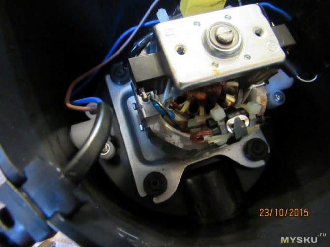
miracles of Chinese technology, a whole sandwich of contacts and a 105-degree plastic thermal fuse. Understanding this good
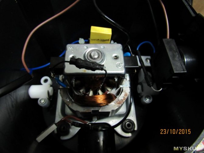
We make our sandwich, already with our additional sensor wrapped in thermal rubber.
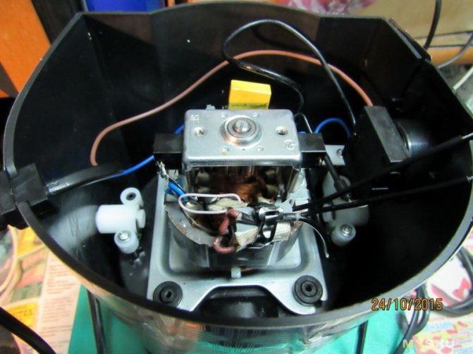
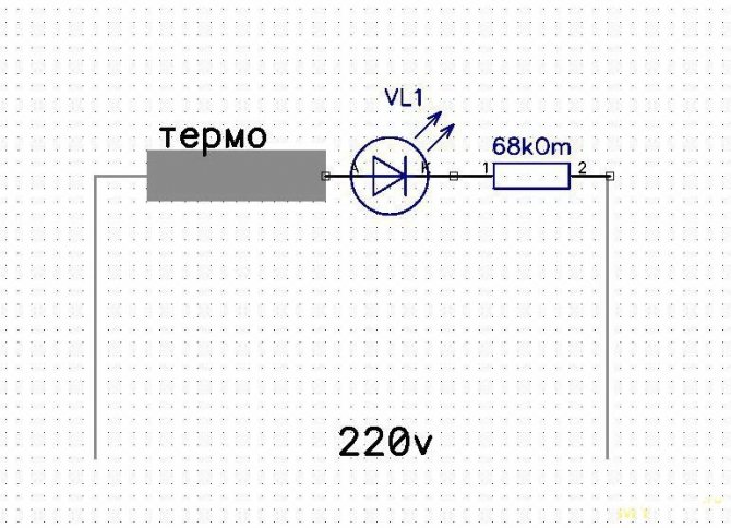
While I put the overheat warning LED
Wiring diagram
Happened
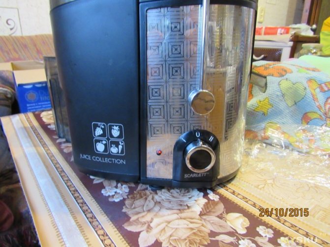
So far so, but in the future, after acquiring the necessary, I will do a protective shutdown. Scheme
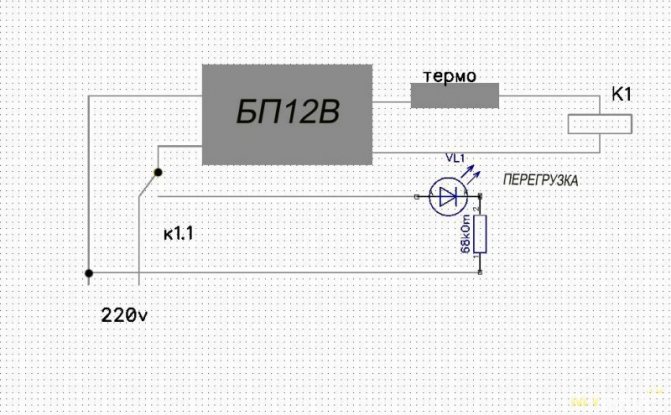
So you can modify any weak electric motor that can burn out due to increased load.
All. I listen to your comments.
Main characteristics
Each TR has individual technical characteristics (TX). The relay must be selected according to the characteristics of the load and the conditions of use when operating an electric motor or other consumer of electricity:
- The value of In.
- Adjustment range of I actuation.
- Voltage.
- Additional management of TR operation.
- Power.
- Operation limit.
- Sensitivity to phase imbalance.
- Trip class.
The rated current value is the value of I for which the TR is designed. It is selected according to the value of In of the consumer to which it is directly connected. In addition, you need to choose with a margin of In and be guided by the following formula: Inr \u003d 1.5 * Ind, where Inr - In TR, which should be 1.5 times more than the rated motor current (Ind).
The I operation adjustment limit is one of the important parameters of the thermal protection device. The designation of this parameter is the adjustment range of the In value.Voltage - the value of the power voltage for which the relay contacts are designed; if the permissible value is exceeded, the device will fail.
Some types of relays are equipped with separate contacts for controlling the operation of the device and the consumer. Power is one of the main parameters of the TR, which determines the output power of the connected consumer or consumer group.
The trip limit or trip threshold is a factor that depends on the rated current. Basically, its value is in the range from 1.1 to 1.5.
Sensitivity to phase imbalance (phase asymmetry) shows the percentage ratio of the phase with imbalance to the phase through which the rated current of the required magnitude flows.
Trip class is a parameter that represents the average tripping time of the TR depending on the multiplicity of the setting current.
The main characteristic by which you need to choose TR is the dependence of the operation time on the load current.