- Adjusting the flow of the working fluid. What to look for when buying?
- Arrangement of the pumping and mixing unit
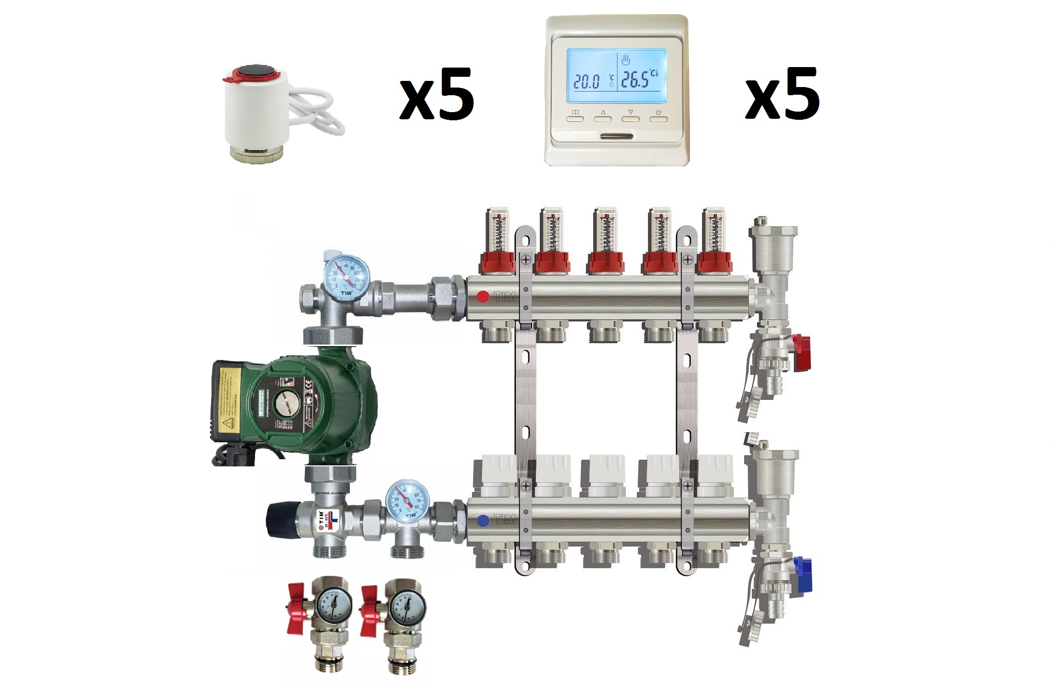
- Elements for Assembly
- Types of mixing units
- With fittings for connecting circuits
- With integrated taps
- with control valves
- Materials and tools
- How to choose a three-way valve
- Why you need to use a mixing unit
- The general concept of the mixing unit
- Why is this design important?
- How the mixing unit works
- Schemes of mixing units
Adjusting the flow of the working fluid. What to look for when buying?
Manual adjustment is made by means of a conventional ball valve. Visually, it is very similar to a simple valve, but has an additional outlet. Armature of this kind is used for forced manual control.
As for automatic adjustment, a special three-way valve is used here, equipped with an electromechanical device for changing the position of the stem. It should be connected to a thermostat in order to be able to adjust the temperature in the room.
Remember that when buying a valve, it is imperative to take into account the technical parameters of the device, which include the following
- Diameter of connection to the heating main.Often this indicator varies from 2 to 4 centimeters, although much depends on the characteristics of the system itself. If the device of a suitable diameter could not be found, then you will have to use special adapters.
- The possibility of installing a servo drive on a three-way valve, the principle of operation is considered at the beginning of the article. Thanks to this, the device will be able to work automatically. This moment is very important if the device is selected for operation in "warm floors" of the water type.
- Finally, this is the throughput of the pipeline. This concept refers to the volume of liquid that can pass through it in a certain time.
Arrangement of the pumping and mixing unit
Each manufacturer offers its own design solutions for mixers for underfloor heating. However, ready-made units, especially imported ones, are quite expensive, while such a device can be assembled independently from individual elements. How to make such a budget option, we will describe further, based on the option with a three-way valve.
Elements for Assembly
Purchase all the components needed to assemble the node.
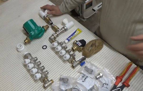
What is required to assemble the mixing unit
The main details for the contour in a room of 20 square meters:
- circulation pump with a capacity of 15/4;
- two temperature-controlled collectors;
- mixing valve;
- two check valves;
- fittings with a union nut (usually 16x2);
- couplings with the transition to the outer and inner radius;
- plumbing linen for sealing joints;
- Unipak silicone sealant.
Underfloor heating manifold
The dimensions of the connecting fittings are selected in accordance with the power of the system and the diameter of the pipeline.
Table. Step by step assembly instructions.


Steps, photo
Description of actions
Step 1
There is an arrow on the mixing valve that shows the direction of movement of the coolant. On the side where it is red, there should be an inlet of a pipe with hot water.
Step 2
At the bottom is the return entry.
Step 3
Take an adapter, separate a small strand of flax and wind it dry on the thread. The shape of the winding does not matter; it is not necessary to hit the thread pitch.
Step 4
Then squeeze a little sealant over the flax and distribute it with your finger along the entire circumference of the thread. Try to do this carefully so that the sealant does not get inside the coupling.
Step 5
Screw the adapter to the mixing valve on the side where the water for the floor circuit will come out.
Step 6
To tighten the connection, you can use the pliers inserted inside the sleeve. The excess sealant squeezed out at the same time should be removed with a napkin.
Step 7
Similarly, on the opposite side (where hot water will come from), a check valve is connected to the mixing tee using an adapter with a double-sided thread. Tighten the connection well with an adjustable wrench and wipe dry again.
Step 8
After the sleeve is well tightened, screw the valve itself
It is very important to set it up correctly. Focus on the arrow on the body, which shows the direction of water movement.
Step 9
The check valve will be located at the bottom of the mixer - where the cooled water from the return pipeline will enter it.
Step 10
A tee with a valve is connected to the check valve, through which the manifold will communicate with the mixer.
Step 11
The mixing unit itself is already assembled
Now we need to attach the rest to it.First, the pump, having previously installed a rubber gasket on the connection.
Step 12
The pump will be on the left, at the outlet of the mixer.
Step 13
From below, a manifold is attached to the tee through an angle adapter.
Step 14
A fitting is screwed onto the outlet of the pump. In this case, it is polypropylene, but it can be any other. The main thing is to make a good connection.
Step 15
In order to later be able to fix the assembly on the wall and provide the collector with an indent for the return pipe to pass under it, use a plumbing clamp. Usually it is attached to a hairpin, but in this case, the master cut off 2 cm from the propylene pipe to use it as a stand.
Step 16
The clamp nut just fits perfectly into the hole in the tube.
Step 17
Install clamps. In this case, there will be three of them: under the return manifold, under the polypropylene fitting to the left of the pump and to the right, under the valve at the hot water inlet.
Step 18
When you buy a complete assembly from the manufacturer, a special screen is included in the kit on which it is installed. Since we assemble it ourselves, a piece of OSB sheet cut to the desired size can be used as a screen. Put the assembled unit on it, put the clamps with stands in the right places and outline their contours so that you can see where to fasten them.
Step 19
Now the collector needs to be removed and fastened with clamps to the panel.
Step 20
To do this, they need to drill thin holes in the center, and screw them to the plate with screws.
Step 21
When the mixing unit is installed in its regular place and fixed with clamps, all that remains is to attach the underfloor heating collector to it from the pump side. Note! In this case, the master assembles this part of the structure from polypropylene, but since you probably do not have a special soldering iron for it, you can use brass fittings.
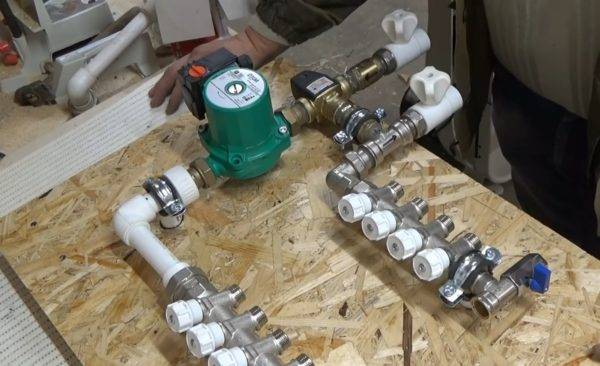
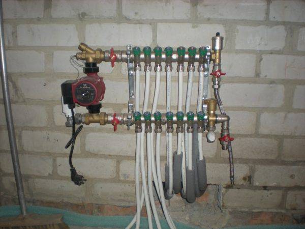
What does the assembled mixing unit look like?
In the end, the hand-assembled mixing unit will look like the one shown in the photo, and we really hope that everything worked out for you.
Types of mixing units
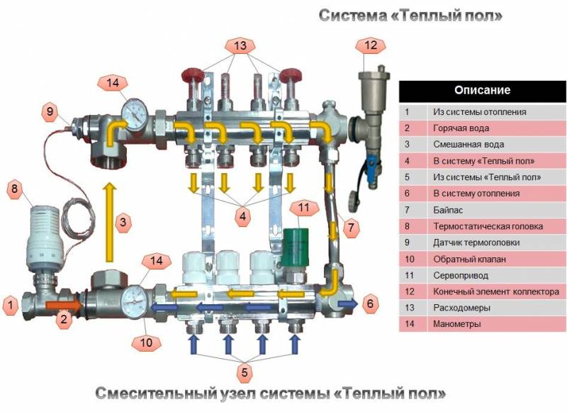
The scheme of operation of the collector for a warm floor is quite simple. The heat carrier from the heating boiler enters the supply distributor. It is recommended to place it on top (above the return comb), however, depending on local installation features, as well as the type of connected mixing unit, it can also be installed below. The collector housing has two or more branches equipped with appropriate shut-off and control valves. For each of the branches, the coolant is redirected to certain TP pipelines. The outlet end of the pipe loop closes on the return manifold, which directs the collected total flow to the heating boiler.
Obviously, in the simplest case, a collector for a water-heated floor is a piece of pipe with a certain number of threaded outlets. However, depending on what final configuration it will receive, the complexity of its assembly, settings and cost can vary significantly. Let us first consider the most popular basic models of distributors for water TS.
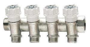
With fittings for connecting circuits
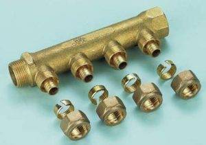
One of the most budgetary, but completely ready-to-use, is a comb with inlet / outlet threads and fittings for connecting metal-plastic or XLPE pipes.
One of these models is shown in the photo.
With integrated taps
In the minimum configuration, you can also find a collector for underfloor heating equipped with two-way ball valves. Such devices do not provide for contour adjustment - they are designed only to turn on or off individual heating branches.
Given that the underfloor heating system is purchased and installed to increase the comfort of residents, which is ensured by fine tuning of the system, the expediency of using such combs is purely selective.
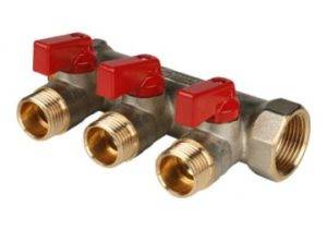 Three-circuit manifold with integrated two-way ball valves
When purchasing these budget options for distributors, it should be borne in mind that their use requires fundamental knowledge, as well as extensive experience in installing heating systems.
In addition, the procurement savings are rather conditional, since all additional equipment will have to be purchased separately. Practically simplified collectors for a warm water floor without modification are only suitable for auxiliary systems for one or two small loops. They are also suitable for several circuits, but having identical thermal and hydraulic characteristics. After all, the design of such combs does not provide the technical possibility of installing control and regulation equipment directly on each branch.


with control valves
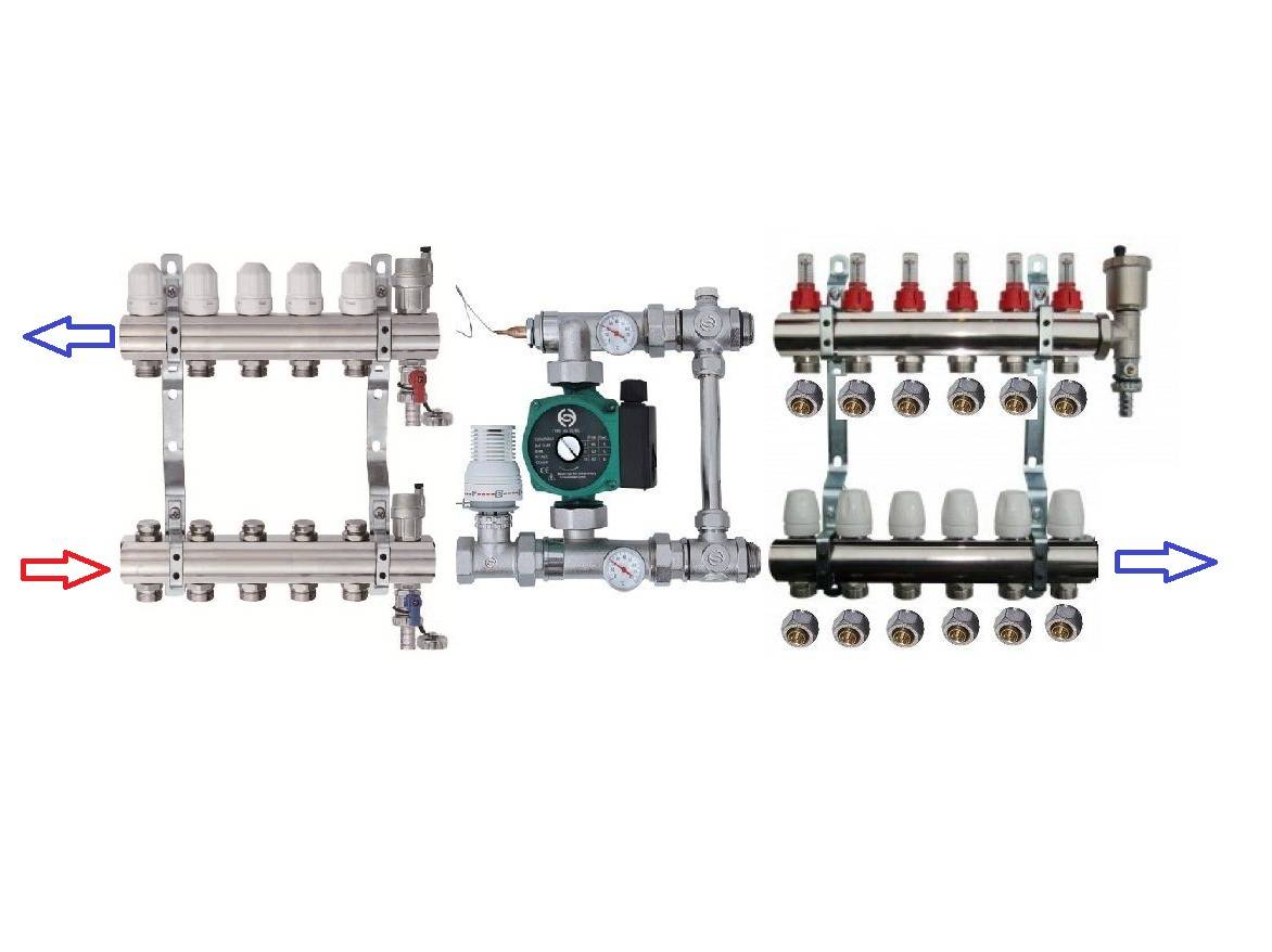
 Example of a manifold with control valves
The next level, both in terms of cost and functionality, is a distribution manifold for underfloor heating with control valves. Such devices, operated in manual mode, can already provide adjustment of the intensity of the coolant supply for individual heating circuits. For them, in most cases, it is technically possible to install actuators with servo drives instead of manual valves.
The actuators can be connected either directly to electronic temperature sensors installed in the premises or to a central programmable control unit.
Materials and tools
The work will require tools and materials. You should also calculate the required amount of materials, and in addition, take care of purchasing the necessary system components.
- boiler;
- collector;
- pump;
- valve for adjustment;
- air outlet;
- valves;
- fitting;
- screws;
- screwdriver;
- cement;
- sand.
In addition to them, the main components of the system should be purchased before installation. The heating boiler is the main element of the heating system. When performing installation work, you can not do without a pressure pump, which can be connected directly to the boiler.
Valves are installed at the inlet of the device. You should also prepare the pipes that will be used to create the wiring. After that, the collector is prepared. This device contains elements used to set the temperature of the system and regulate it.
Also, the owner must purchase pipes for laying on the floor surface. In addition to them, fittings are bought, which during operation are used to lay the main line.Also, these elements are also used to connect laid pipes to the underfloor heating system.
Pipes intended for underfloor heating can be made of polypropylene. The best choice is products with a fiberglass reinforcing layer. Their advantage is that at high temperatures they expand less. In addition to them, polyethylene pipes can be used, since they expand to a minimum when heated.
When installing surface heating systems, polyethylene pipes are most often used. You should choose products with a diameter of 18 to 22 mm. The pipe must be designed for a working pressure of up to 10 bar and a temperature of up to 90 degrees Celsius. Some pipe models are equipped with oxygen protection and have additional layers in their structure. However, most often, owners opt for polyethylene pipes, since their cost is quite low. If for the owner, when installing a warm floor, the most important thing is to reduce the cost of installing the system, then polyethylene pipes are usually chosen.
By its appearance, the collector is a device that has taps. In another way, it is called a splitter. It is mainly used to connect different circuits of the system.
The main line connects different circuits that provide delivery heated water and outlet cold.
When installing a "warm" floor, two collectors are arranged. The first acts as a splitter and is designed to distribute heated water. The second is used to collect the cooled coolant.
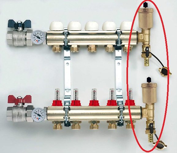
The devices used to configure the system are located in the design of the splitter:
- valves;
- drain adjustment device;
- spare drain;
- air from water.
How to choose a three-way valve
An important point is the choice of a suitable three-way valve. In order to immediately choose it correctly, without wasting time on a subsequent exchange, you must be guided by the following tips:
1. Find out in advance the flow rate of the coolant in your system. This can be taken from the documentation supplied with the heating boiler. Then you can choose the valve by capacity.


2. Valve control method. It can be operated manually or automatically. If it is more convenient for you to control the operation of the valve manually, then choose an inexpensive three-way manual type valve. If you prefer automation, then decide on the type of automatic control. For example, the valve will respond to the temperature of the coolant or to the temperature of the room air.
3. Range of changeable temperatures. Knowing the temperature of the coolant that will circulate in the heating system, choose a device with the appropriate temperature characteristics.
4. Housing material. Such taps are most often made of brass, which has good anti-corrosion properties. It is this material that is recommended for purchase. Cast iron taps are produced only in large diameters, so their use is very specific.
5. Diameter of nozzles. It must correspond to the diameter of the heating pipelines available in the house. Then you do not have to buy additional adapters.
By choosing and installing a three-way thermostatic faucet correctly, you will provide your home with a reliable heating system, depending on your needs.Thus, not only will the maximum level of comfort in the house be achieved, but energy resources will also be saved. Such an approach in the modern world is the only true one in all respects.
A three-way thermostatic mixing valve is a product whose purpose is to provide the ability to control and maintain the set temperature of the coolant in the heating system. A feature of the device is that it is equipped with one input and two outputs or two inputs and one output. This design allows you to install a three-way valve for the boiler at branch points or where it is necessary to ensure the mixing of the coolant, for example, hot and cold water.
Why you need to use a mixing unit
So for radiators, water temperature is used from 60 to 90 degrees, which directly exits the boiler. But for a warm floor, the recommended liquid temperature is about 30-40 degrees.
The principle of operation is similar to the operation of an ordinary mixer.
If we connect the circuits to the collector along with the batteries, then the warm floor will receive a large amount of heat, and this is not acceptable for a number of reasons.
- Since the screed layer above the pipes is approximately 3-6 cm, a high temperature will lead to cracking and deformation of the layer.
- Pipes that are inside the screed will experience a greater load, which will lead to local stresses, since at high temperatures the linear expansion is much greater, and the pipes are limited by a layer of concrete screed. All this will lead to a rapid failure of the pipes.
- Floor coverings do not like hot surfaces, they begin to delaminate and crack (laminate, parquet, parquet).In the case of ceramic tiles, delamination is possible. Linoleum loses its shape, dries out and deforms.
- An overheated floor surface disturbs the microclimate of the premises.
- If we accept that the floor surface will warm up to 50 degrees, then it will be impossible to walk on it barefoot.
From the above, it follows that the mixing unit is simply not replaceable. Since it is simply stupid and unprofitable to hang a separate boiler on the “warm floor” system.
And it is not difficult to make minor changes to the heating system scheme (if the heating has already been installed). And if you mount the circuit from scratch, then this device should be provided in advance.
It should be said that there are boilers on sale that immediately provide for the technology of heating and outputting two liquid carriers of different temperatures at once. This equipment is very expensive and not popular.


This is interesting: Decorative stone effect panels for outdoor decoration
The general concept of the mixing unit
In order for the task to be carried out easily, the performer must understand the purpose, the principles of functioning of the completed structure. This rule also applies to the installation of the mixing unit.
Why is this design important?
Consider what kind of work does the mixing unit of the underfloor heating.
First of all, it is necessary to clarify that the temperature of the liquid circulating through the contours of the warm floor is two times lower than standard heating systems with radiators and convectors.
In the usual, high-temperature system, water heated to 70-80 degrees and above is used. For the specified operating modes, they were made before and are now being created heat mains, heating boilers are being produced.
The fluid temperature allowed in a classic heating system is not suitable for underfloor heating. This is due to such factors:
- Based on the area of active heat exchange (this is almost the entire floor) and the impressive heat capacity of the screed with laid pipes for underfloor heating, it can be assumed that +35 degrees of water temperature is enough to heat the room.
- The comfortable perception of surface heating with bare feet has a characteristic framework - it is optimal for the foot to stand on the floor heated to a maximum of 30 degrees. If the floor is hot, the feet are unpleasant and uncomfortable.
- Standard floor finishes are not suitable for high heat from below. High temperature provokes deformation of the floor, the appearance of cracks between parts, breakage of the interlock, waves and humps on the surface of the coating, etc.
- High temperatures can greatly damage the concrete screed in which the underfloor heating pipes are mounted.
- Strong heating negatively affects the pipes of the laid circuits. During installation, these elements are rigidly fixed and do not expand under the influence of thermal effects. If hot water is constantly in the pipes, tension will begin to rise in them. Over a period of time, this phenomenon will quickly ruin the pipes and cause leaks.
Due to the growing popularity of underfloor heating, manufacturers began to offer boilers with a similar principle of operation. But many experts note the pointlessness of buying a special water heater. Firstly, a "clean" warm floor is often used in certain areas and combined with a standard floor.Secondly, instead of two boilers, it is better to clearly define the placement of a warm and classic floor and put a mixing unit on the border.
Another factor explaining the feasibility of using a mixing unit. When installing a warm floor, it is necessary to ensure the correct circulation of fluid in each floor circuit, and in fact they are sometimes more than 8 meters in length, bend several times, turn sharply.
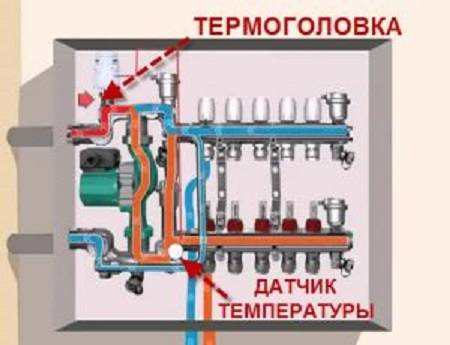
How the mixing unit works
The heated liquid, when it enters the underfloor heating manifold, immediately enters the valve in which the thermostat is stored. If the water for the pipes is very hot, the valve opens and lets cold water into the heated liquid, mixing them to the optimum temperature.
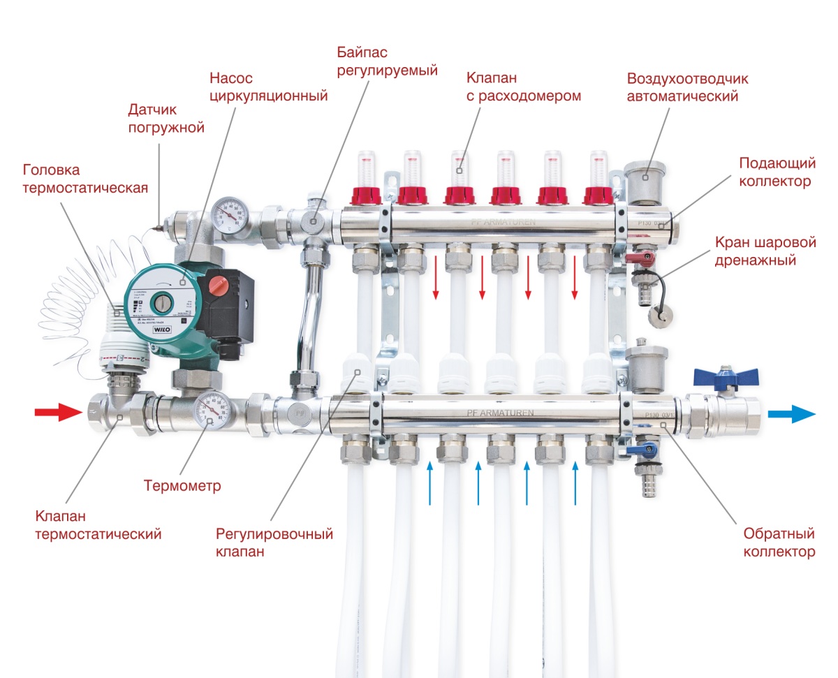
The manifold of the system is equipped with two main functions. In addition to mixing water in order to obtain the required temperature, it makes the liquid circulate. For this, the system is equipped with special circulation equipment. When water is constantly moving through the pipes, it evenly heats the entire floor. For better functionality, the collector is equipped with:
- shut-off valves;
- drainage valves;
- air vents.
If a warm floor is installed in only one room, a pump must also be installed here. So that the box does not take up much space, a niche is first made for it in the wall. If the underfloor heating will spread in all rooms, it is more rational to create a common collector cabinet.
Schemes of mixing units
- Connectors (No. 6) are connected to the pipes.
- The supply of hot coolant from the boiler is connected to output No. 10, and the return is connected to No. 11.
- The scheme can be supplemented with an automatic air vent.
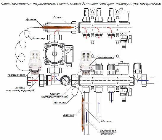
The second version of the node is also suitable for heating 15-20 sq.m., but unlike the previous version, it has automatic adjustment, due to the installed thermal head with a remote sensor.
- To connect it, the mixing valve (No. 1) is mounted with a “+” sign in the direction of the American tap from the supply.
- The supply and return are connected to American women through connectors with external threads (No. 4 - inlet, No. 7 water outlet).
- The operation of the circulation pump (No. 18) is directed towards the mixing valve (No. 1).
- The underfloor heating circuits are connected to outputs numbered 12 and 22.
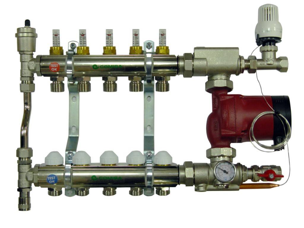
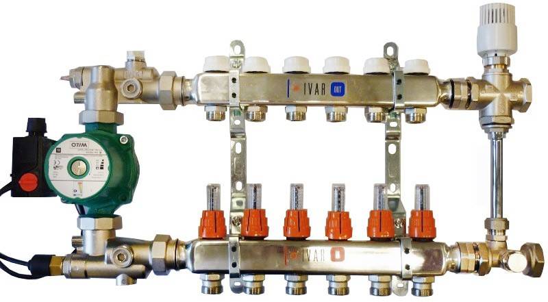
 Pumping and mixing unit from Valtec
The third version of the collector unit is already suitable for 2-4 heating circuits with an area of 20-60 square meters. m. The diagram shows an example with manual control.


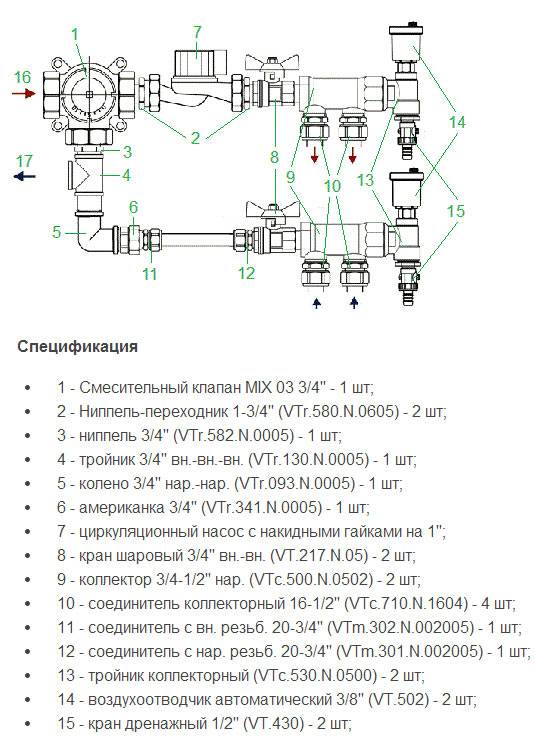
- To connect, the supply from the boiler is connected to terminal No. 16, and the return to terminal No. 17.
- For the system to work well, the length of the loops should be approximately the same.
- The diagram shows an option for two circuits, but if three or four pieces are to be connected, then the manifolds (9) are replaced with one adjustable manifold and one with ball valves (VTc.560n and VTc.580n).
The following scheme is also suitable for heating rooms up to 60 square meters. m., for 2-4 circuits, but it has automatic temperature control.
- The supply is connected through the upper American tap No. 3, and the return is connected to the lower tap.
- The pump must work towards mixing valve number 2.
- The valve itself is installed with a plus sign in the direction of supply from the boiler.
- The contours for the warm floor are attached to the collectors (12).
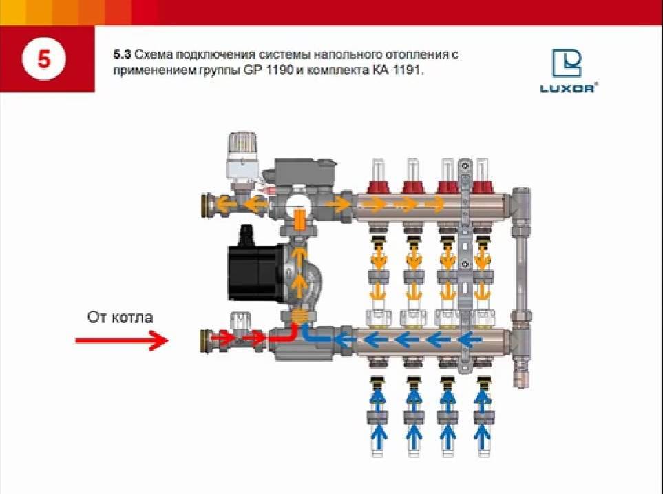
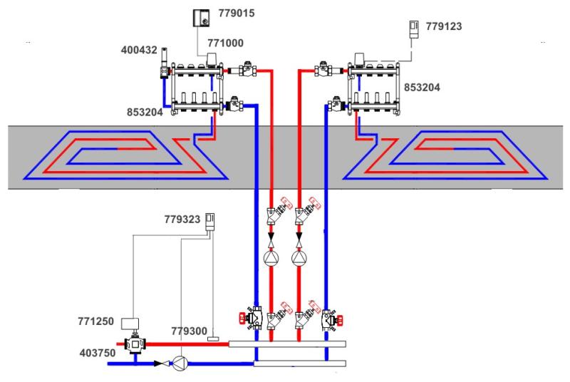
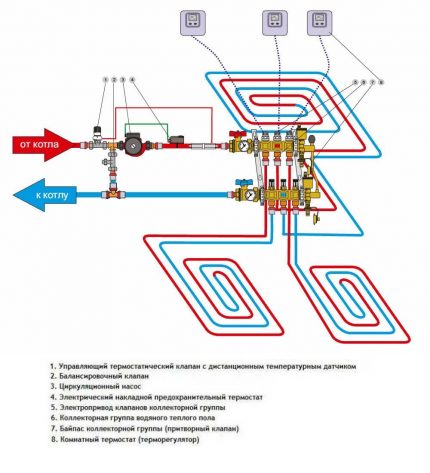
 And the last scheme with auto-adjustment is suitable for a floor heating system for 3-12 circuits, up to 150 sq. m.
Specification:
- 1 manifold assembly for the required number of outlets (VTc.594/VTc.596);
- circular pump 180 mm;
- 2 fittings (for each circuit) VT.4420.NE.16 of the Eurocone standard for connecting metal-plastic pipes.
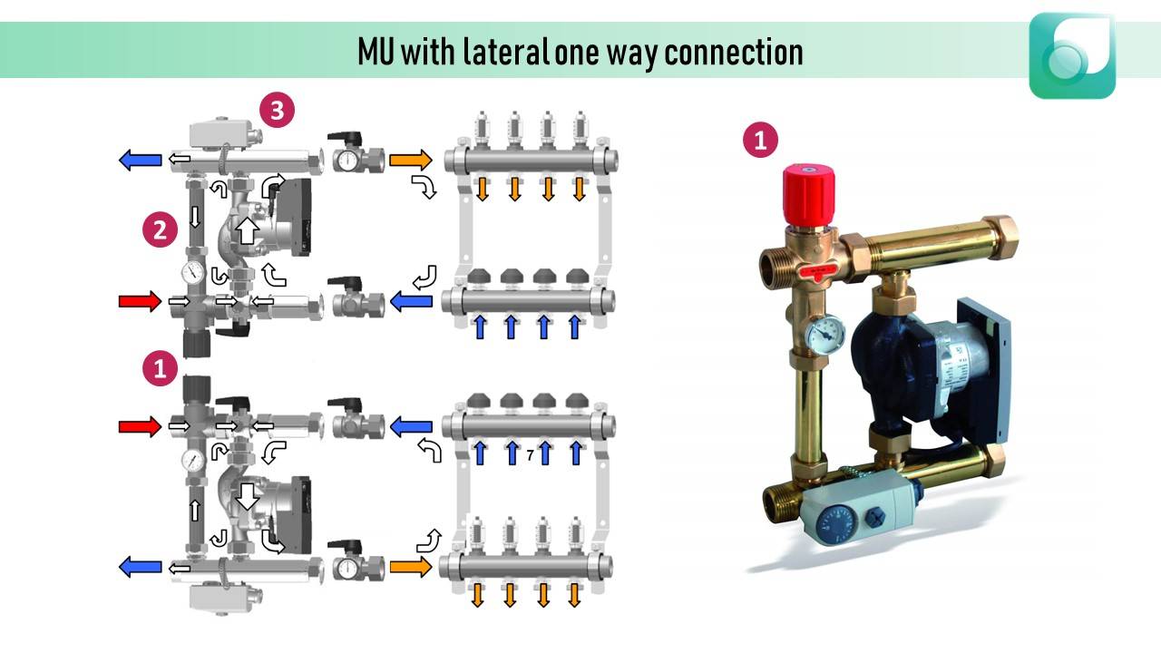
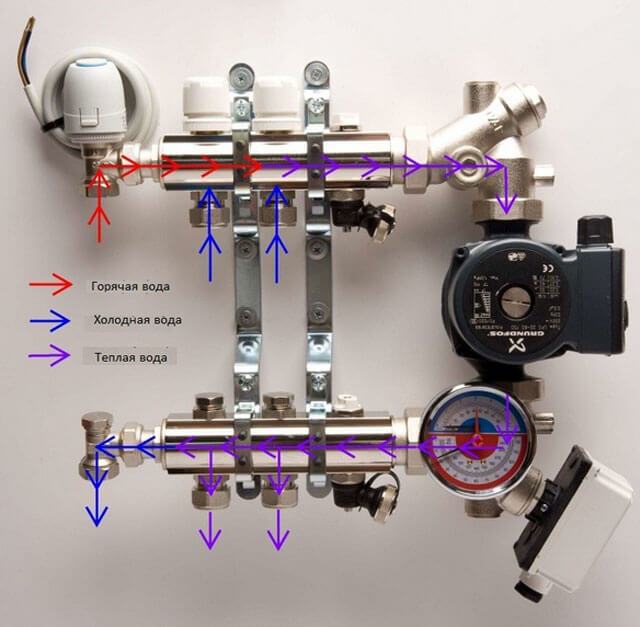
The circulation of the coolant in such a collector is shown in the figure. The supply is connected to the upper outlet, the return to the lower. The operation of the pump is directed downward, so the lower manifold becomes the supply for the underfloor heating circuits (orange in the photo), and the upper one goes to the return line (blue).
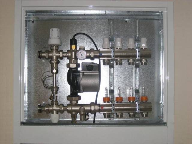 manifold cabinet
A collector for a water-heated floor is usually installed in a manifold cabinet. They are both internal and external. Their standard depth is 12 cm, so not every node can fit, especially if large thermal sensors are installed. In this case, it is better to choose an internal cabinet, the depth of which is increased by deepening the back wall.


