- Variety of ventilation systems
- Do I need to focus on SNiP?
- General principles of calculation
- Rules for determining air speed
- No. 1 - sanitary noise level standards
- No. 2 - vibration level
- No. 3 - air exchange rate
- Initial data for calculations
- Frontal section
- 3 Power calculation
- Air Velocity Calculation Algorithm
- Calculation of air velocity in a duct by section: tables, formulas
- General principles of calculation
- Formulas for calculation
- Some useful tips and notes
- The importance of air exchange
- We start designing
- Calculation algorithm
- Calculation of cross-sectional area and diameter
- Calculation of pressure loss on resistance
- The need for good ventilation
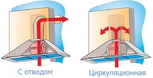
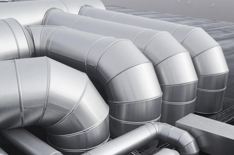
Variety of ventilation systems
The supply system has a complicated mechanism: before the air enters the room, it passes through the air intake grille and valve and ends up in the filter element. After it is sent to the heater, and then to the fan. And only after this stage reaches the finish line. This type of ventilation system is suitable for rooms with a small area.
Combined supply and exhaust systems is considered the most efficient way of ventilation. This is due to the fact that polluted air does not linger in the room for a long time, and at the same time fresh air constantly enters.It is worth noting that the diameter of the duct and its thickness directly depend on the desired type of ventilation system, as well as the choice of its design (normal or flexible).
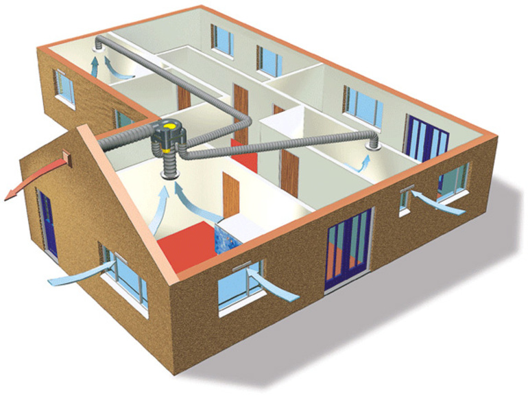
According to the method of movement of air masses in the room, experts distinguish between natural and mechanical ventilation systems. If the building does not use mechanical equipment to supply and clean air, then this type is called natural. In this case, there are often no air ducts. The best option is a mechanical ventilation system, especially when the weather is calm outside. Such a system allows air to enter and leave the room through the use of various fans and filters. Also, using the remote control, you can adjust the comfortable indicators of temperature and pressure inside the room.
In addition to the above classifications, there are ventilation systems of general and local type. In production, where there is no way to eliminate air from places-sources of pollution, general ventilation is used. In this way, harmful air masses are constantly replaced by clean ones. If the polluted air can be eliminated near the source of its occurrence, then local ventilation is used, which is most often used in domestic conditions.
Do I need to focus on SNiP?
In all calculations that we carried out, the recommendations of SNiP and MGSN were used. This regulatory documentation allows you to determine the minimum allowable ventilation performance that ensures a comfortable stay of people in the room.In other words, the requirements of SNiP are primarily aimed at minimizing the cost of the ventilation system and the cost of its operation, which is relevant when designing ventilation systems for administrative and public buildings.
In apartments and cottages, the situation is different, because you are designing ventilation for yourself, and not for the average resident, and no one forces you to adhere to the recommendations of SNiP. For this reason, the performance of the system can be either higher than the calculated value (for greater comfort) or lower (to reduce energy consumption and system cost). In addition, the subjective feeling of comfort is different for everyone: 30–40 m³ / h per person is enough for someone, and 60 m³ / h will not be enough for someone.
However, if you do not know what kind of air exchange you need to feel comfortable, it is better to follow the recommendations of SNiP. Since modern air handling units allow you to adjust the performance from the control panel, you can find a compromise between comfort and economy already during the operation of the ventilation system.
General principles of calculation
Air ducts can be made of various materials (plastic, metal) and have different shapes (round, rectangular). SNiP regulates only the dimensions of exhaust devices, but does not standardize the amount of intake air, since its consumption, depending on the type and purpose of the room, can vary greatly. This parameter is calculated by special formulas, which are selected separately. The norms are set only for social facilities: hospitals, schools, preschool institutions. They are prescribed in SNiPs for such buildings. At the same time, there are no clear rules for the speed of air movement in the duct.There are only recommended values and norms for forced and natural ventilation, depending on its type and purpose, they can be found in the relevant SNiPs. This is reflected in the table below. The speed of air movement is measured in m/s.
Recommended air speeds
You can supplement the data in the table as follows: with natural ventilation, the air velocity cannot exceed 2 m/s, regardless of its purpose, the minimum allowable is 0.2 m/s. Otherwise, the renewal of the gas mixture in the room will be insufficient. With forced exhaust, the maximum allowable value is 8 -11 m / s for main air ducts. These norms should not be exceeded, because this will create too much pressure and resistance in the system.
Rules for determining air speed
The speed of air movement is closely related to such concepts as noise level and vibration level in the ventilation system. The air passing through the channels creates a certain noise and pressure, which increases with the number of turns and bends.
The greater the resistance in the pipes, the lower the air speed and the higher the fan performance. Consider the norms of concomitant factors.
No. 1 - sanitary noise level standards
The standards specified in the SNiP relate to residential (private and multi-apartment buildings), public and industrial type premises.
In the table below, you can compare the norms for different types of premises, as well as areas adjacent to buildings.
Part of the table from No. 1 SNiP-2-77 from the paragraph "Protection from noise".The maximum allowable norms related to night time are lower than daytime values, and the norms for adjacent territories are higher than for residential premises
One of the reasons for the increase in accepted standards may just be an improperly designed duct system.
Sound pressure levels are presented in another table:
When commissioning ventilation or other equipment related to ensuring a favorable, healthy microclimate in the room, only a short-term excess of the indicated noise parameters is allowed.
No. 2 - vibration level
The power of the fans is directly related to the level of vibration.
The maximum vibration threshold depends on several factors:
- duct dimensions;
- the quality of gaskets that reduce the level of vibration;
- pipe material;
- the speed of air flow through the channels.
The norms that should be followed when choosing ventilation devices and when calculating air ducts are presented in the following table:
Maximum permissible values of local vibration. If during the test the actual values are higher than the norm, then the duct system is designed with technical flaws that need to be corrected, or the fan power is too high
The air speed in shafts and channels should not affect the increase in vibration indicators, as well as the associated sound vibration parameters.
No. 3 - air exchange rate
Air purification occurs due to the process of air exchange, which is divided into natural or forced.
In the first case, it is carried out when opening doors, transoms, vents, windows (and is called aeration) or simply by infiltration through cracks at the junctions of walls, doors and windows, in the second - with the help of air conditioners and ventilation equipment.
The change of air in a room, utility room or workshop should occur several times per hour so that the degree of pollution of the air masses is acceptable. The number of shifts is a multiplicity, a value that is also necessary to determine the air velocity in the ventilation ducts.


The multiplicity is calculated according to the following formula:
N=V/W,
where:
- N is the frequency of air exchange, once per hour;
- V is the volume of clean air that fills the room in 1 hour, m³/h;
- W is the volume of the room, m³.
In order not to perform additional calculations, the average multiplicity indicators are collected in tables.
For example, the following table of air exchange rates is suitable for residential premises:
Judging by the table, a frequent change of air masses in a room is necessary if it is characterized by high humidity or air temperature - for example, in a kitchen or bathroom. Accordingly, in case of insufficient natural ventilation, forced circulation devices are installed in these rooms.
What happens if the air exchange rate standards are not met or will be, but not enough?
One of two things will happen:
The multiplicity is below the norm. Fresh air stops replacing polluted air, as a result of which the concentration of harmful substances in the room increases: bacteria, pathogens, hazardous gases
The amount of oxygen, which is important for the human respiratory system, decreases, while carbon dioxide, on the contrary, increases.Humidity rises to a maximum, which is fraught with the appearance of mold.
Multiplicity above the norm
Occurs if the speed of air movement in the channels exceeds the norm. This negatively affects the temperature regime: the room simply does not have time to heat up. Excessively dry air provokes diseases of the skin and respiratory apparatus.
In order for the air exchange rate to comply with sanitary standards, it is necessary to install, remove or adjust ventilation devices, and, if necessary, replace air ducts.
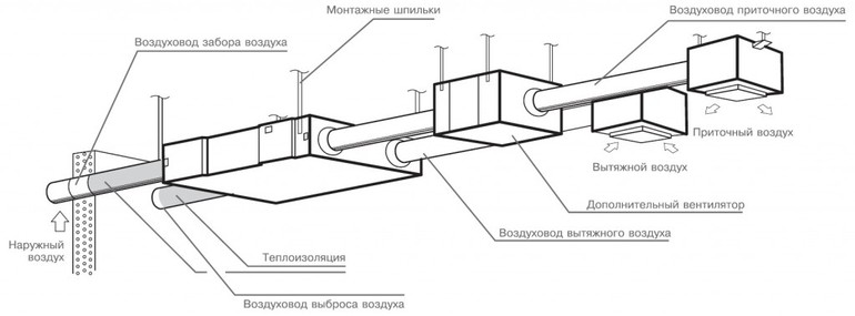
Initial data for calculations
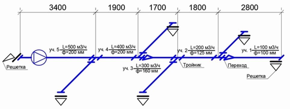
When the scheme of the ventilation system is known, the dimensions of all air ducts are selected and additional equipment is determined, the scheme is depicted in a frontal isometric projection, that is, axonometry. If it is performed in accordance with current standards, then all the information necessary for the calculation will be visible on the drawings (or sketches).
- With the help of floor plans, you can determine the length of the horizontal sections of air ducts. If on the axonometric diagram there are marks of the heights at which the channels pass, then the length of the horizontal sections will also become known. Otherwise, sections of the building with laid air duct routes will be required. And in the extreme case, when there is not enough information, these lengths will have to be determined using measurements at the installation site.
- The diagram should show with the help of symbols all additional equipment installed in the channels. These can be diaphragms, motorized dampers, fire dampers, as well as devices for distributing or extracting air (grilles, panels, umbrellas, diffusers).Each unit of this equipment creates resistance in the path of the air flow, which must be taken into account in the calculation.
- In accordance with the regulations on the diagram, near the conditional images of the air ducts, the air flow rates and the dimensions of the channels should be affixed. These are the defining parameters for calculations.
- All shaped and branching elements must also be reflected in the diagram.
If such a scheme does not exist on paper or in electronic form, then you will have to draw it at least in a draft version, you cannot do without it in calculations.
Frontal section
2. Selection and calculation of heaters - stage two. Having decided on the required thermal power of the water heater
supply unit for heating the required volume, we find the frontal section for the passage of air. Frontal
section - working internal section with heat-releasing tubes through which flows directly pass
cold air blown. G is the mass air flow, kg/hour; v - mass air velocity - for finned heaters is taken in
range 3 - 5 (kg/m²•s). Permissible values - up to 7 - 8 kg / m² • s.
Below is a table with the data of two, three and four-row air heaters of the KSK-02-KhL3 type manufactured by T.S.T.
The table shows the main technical specifications for calculation and selection of all models heat exchanger data: area
heating surfaces and frontal section, connecting pipes, collector and free section for the passage of water, length
heating tubes, number of strokes and rows, weight. Ready-made calculations for various volumes of heated air, temperature
of incoming air and coolant graphs can be viewed by clicking on the model of the ventilation heater you have chosen from the table.
Ksk2 heaters Ksk3 heaters Ksk4 heaters
| Name of heater | Area, m² | Length of the heat-releasing element (in the light), m | Number of strokes on the internal coolant | Number of rows | Weight, kg | ||||
|---|---|---|---|---|---|---|---|---|---|
| heating surfaces | front section | collector section | branch pipe section | open section (medium) for the passage of the coolant | |||||
| Ksk 2-1 | 6.7 | 0.197 | 0.00152 | 0.00101 | 0.00056 | 0.530 | 4 | 2 | 22 |
| Ksk 2-2 | 8.2 | 0.244 | 0.655 | 25 | |||||
| Ksk 2-3 | 9.8 | 0.290 | 0.780 | 28 | |||||
| Ksk 2-4 | 11.3 | 0.337 | 0.905 | 31 | |||||
| Ksk 2-5 | 14.4 | 0.430 | 1.155 | 36 | |||||
| Ksk 2-6 | 9.0 | 0.267 | 0.00076 | 0.530 | 27 | ||||
| Ksk 2-7 | 11.1 | 0.329 | 0.655 | 30 | |||||
| Ksk 2-8 | 13.2 | 0.392 | 0.780 | 35 | |||||
| Ksk 2-9 | 15.3 | 0.455 | 0.905 | 39 | |||||
| Ksk 2-10 | 19.5 | 0.581 | 1.155 | 46 | |||||
| Ksk 2-11 | 57.1 | 1.660 | 0.00221 | 0.00156 | 1.655 | 120 | |||
| Ksk 2-12 | 86.2 | 2.488 | 0.00236 | 174 |
| Name of heater | Area, m² | Length of the heat-releasing element (in the light), m | Number of strokes on the internal coolant | Number of rows | Weight, kg | ||||
|---|---|---|---|---|---|---|---|---|---|
| heating surfaces | front section | collector section | branch pipe section | open section (medium) for the passage of the coolant | |||||
| KSK 3-1 | 10.2 | 0.197 | 0.00164 | 0.00101 | 0.00086 | 0.530 | 4 | 3 | 28 |
| KSK 3-2 | 12.5 | 0.244 | 0.655 | 32 | |||||
| Ksk 3-3 | 14.9 | 0.290 | 0.780 | 36 | |||||
| Ksk 3-4 | 17.3 | 0.337 | 0.905 | 41 | |||||
| Ksk 3-5 | 22.1 | 0.430 | 1.155 | 48 | |||||
| Ksk 3-6 | 13.7 | 0.267 | 0.00116 (0.00077) | 0.530 | 4 (6) | 37 | |||
| Ksk 3-7 | 16.9 | 0.329 | 0.655 | 43 | |||||
| Ksk 3-8 | 20.1 | 0.392 | 0.780 | 49 | |||||
| Ksk 3-9 | 23.3 | 0.455 | 0.905 | 54 | |||||
| Ksk 3-10 | 29.7 | 0.581 | 1.155 | 65 | |||||
| KSK 3-11 | 86.2 | 1.660 | 0.00221 | 0.00235 | 1.655 | 4 | 163 | ||
| Ksk 3-12 | 129.9 | 2.488 | 0.00355 | 242 |
| Name of heater | Area, m² | Length of the heat-releasing element (in the light), m | Number of strokes on the internal coolant | Number of rows | Weight, kg | ||||
|---|---|---|---|---|---|---|---|---|---|
| heating surfaces | front section | collector section | branch pipe section | open section (medium) for the passage of the coolant | |||||
| Ksk 4-1 | 13.3 | 0.197 | 0.00224 | 0.00101 | 0.00113 | 0.530 | 4 | 4 | 34 |
| KSK 4-2 | 16.4 | 0.244 | 0.655 | 38 | |||||
| Ksk 4-3 | 19.5 | 0.290 | 0.780 | 44 | |||||
| Ksk 4-4 | 22.6 | 0.337 | 0.905 | 48 | |||||
| Ksk 4-5 | 28.8 | 0.430 | 1.155 | 59 | |||||
| Ksk 4-6 | 18.0 | 0.267 | 0.00153 (0.00102) | 0.530 | 4 (6) | 43 | |||
| KSK 4-7 | 22.2 | 0.329 | 0.655 | 51 | |||||
| Ksk 4-8 | 26.4 | 0.392 | 0.780 | 59 | |||||
| Ksk 4-9 | 30.6 | 0.455 | 0.905 | 65 | |||||
| Ksk 4-10 | 39.0 | 0.581 | 1.155 | 79 | |||||
| KSK 4-11 | 114.2 | 1.660 | 0.00221 | 0.00312 | 1.655 | 4 | 206 | ||
| Ksk 4-12 | 172.4 | 2.488 | 0.00471 | 307 |
What to do if during the calculation, we get the required cross-sectional area, and in the table for the selection of heaters
Ksk, there are no models with such an indicator. Then we accept two or more heaters of the same number,
so that the sum of their areas corresponds to or approaches the desired value. For example, when we calculate
the required cross-sectional area was obtained - 0.926 m². There are no air heaters with this value in the table.
We accept two KSK 3-9 heat exchangers with an area of 0.455 m² (in total this gives 0.910 m²) and mount them according to
air in parallel.
When choosing a two, three or four row model (the same numbers of heaters - have the same area
frontal section), we focus on the fact that the heat exchangers KSk4 (four rows) with the same incoming
temperature of the air, the graph of the coolant and the performance of the air, they heat it by an average of eight to twelve
degrees more than KSK3 (three rows of heat-carrying tubes), fifteen to twenty degrees more than KSK2
(two rows of heat-carrying tubes), but have greater aerodynamic resistance.
3 Power calculation
Heating of large rooms can be organized using one or more water heaters. In order for their work to be efficient and safe, the power of the devices is preliminarily calculated. For this, the following indicators are used:
- Amount of supply air to be heated in one hour. Can be measured in m³ or in kg.
- Outside temperature for a specific region.
- End temperature.
- Temperature graph of water.
The calculations are done in several stages. First of all, according to the formula Af = Lρ / 3600 (ϑρ), the frontal heating area is determined. In this formula:
- l is the volume of supply air;
- ρ is the density of the outside air;
- ϑρ is the mass velocity of air flows in the calculated section.
To find out how much power is required to heat a certain volume of air masses, you need to calculate the total flow of heated air per hour by multiplying the density by the volume of supply flows.The density is calculated by adding the temperature at the inlet and outlet of the apparatus and dividing the resulting sum by two. For ease of use, this indicator is entered in special tables.
For example, the calculations will be as follows. Equipment with a capacity of 10,000 mᶾ / hour must heat the air from -30 to +20 degrees. The water temperature at the inlet and outlet of the heater is 95 and 50 degrees, respectively. Using mathematical operations, it is determined that the mass flow of air flows is 13180 kg / h.
All available parameters are substituted into the formula, density and specific heat capacity are taken from the table. It turns out that heating requires a power of 185,435 watts. When choosing a suitable heater, this value must be increased by 10-15% (no more) in order to ensure a power reserve.
Air Velocity Calculation Algorithm
Given the above conditions and the technical parameters of a particular room, it is possible to determine the characteristics of the ventilation system, as well as calculate the air velocity in the pipes.
You should rely on the frequency of air exchange, which is the determining value for these calculations.
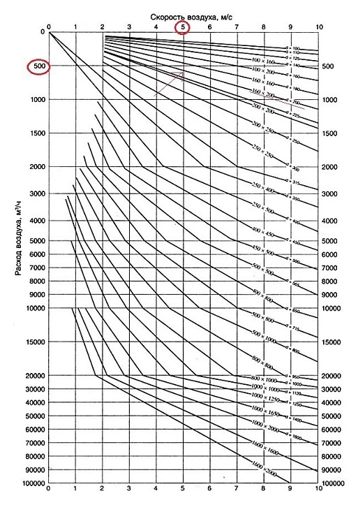
To clarify the flow parameters, a table is useful:
The table shows the dimensions of rectangular ducts, that is, their length and width are indicated. For example, when using ducts 200 mm x 200 mm at a speed of 5 m/s, the air flow will be 720 m³/h
To independently make calculations, you need to know the volume of the room and the rate of air exchange for a room or hall of a given type.
For example, you need to find out the parameters for a studio with a kitchen with a total volume of 20 m³. Let's take the minimum multiplicity value for the kitchen - 6. It turns out that within 1 hour the air channels should move about L = 20 m³ * 6 = 120 m³.


It is also necessary to find out the cross-sectional area of the air ducts installed in the ventilation system. It is calculated using the following formula:
S = πr2 = π/4*D2,
where:
- S is the cross-sectional area of the duct;
- π is the number "pi", a mathematical constant equal to 3.14;
- r is the radius of the duct section;
- D is the diameter of the duct section.
Assume that the diameter of the duct round shape is 400 mm, we substitute it into the formula and get:
S \u003d (3.14 * 0.4²) / 4 \u003d 0.1256 m²
Knowing the cross-sectional area and flow rate, we can calculate the speed. The formula for calculating the airflow rate:
V=L/3600*S,
where:
- V is the speed of the air flow, (m/s);
- L - air consumption, (m³ / h);
- S - cross-sectional area of air channels (air ducts), (m²).
We substitute the known values, we get: V \u003d 120 / (3600 * 0.1256) \u003d 0.265 m / s
Therefore, in order to provide the required air exchange rate (120 m3/h) when using a round duct with a diameter of 400 mm, it will be necessary to install equipment that allows increasing the air flow rate to 0.265 m/s.
It should be remembered that the factors described earlier - the parameters of the vibration level and the noise level - directly depend on the speed of air movement.
If the noise exceeds the norm, you will have to reduce the speed, therefore, increase the cross section of the ducts. In some cases, it is enough to install pipes from a different material or replace the curved channel fragment with a straight one.
Calculation of air velocity in a duct by section: tables, formulas
When calculating and installing ventilation, much attention is paid to the amount of fresh air entering through these channels. For calculations, standard formulas are used, which well reflect the relationship between the dimensions of exhaust devices, movement speed and air consumption.
Some norms are prescribed in SNiPs, but for the most part they are advisory in nature.
General principles of calculation
Air ducts can be made of various materials (plastic, metal) and have different shapes (round, rectangular). SNiP regulates only the dimensions of exhaust devices, but does not standardize the amount of intake air, since its consumption, depending on the type and purpose of the room, can vary greatly. This parameter is calculated by special formulas, which are selected separately.
The norms are set only for social facilities: hospitals, schools, preschool institutions. They are prescribed in SNiPs for such buildings. At the same time, there are no clear rules for the speed of air movement in the duct. There are only recommended values and norms for forced and natural ventilation, depending on its type and purpose, they can be found in the relevant SNiPs. This is reflected in the table below.
The speed of air movement is measured in m/s.
Recommended air speeds
You can supplement the data in the table as follows: with natural ventilation, the air velocity cannot exceed 2 m/s, regardless of its purpose, the minimum allowable is 0.2 m/s. Otherwise, the renewal of the gas mixture in the room will be insufficient. With forced exhaust, the maximum allowable value is 8 -11 m / s for main air ducts.These norms should not be exceeded, because this will create too much pressure and resistance in the system.
Formulas for calculation
To carry out all the necessary calculations, you need to have some data. To calculate air speed, you need the following formula:
ϑ= L / 3600*F, where
ϑ - air flow velocity in the pipeline of the ventilation device, measured in m/s;
L is the flow rate of air masses (this value is measured in m3/h) in that section of the exhaust shaft for which the calculation is made;
F is the cross-sectional area of the pipeline, measured in m2.
According to this formula, the air velocity in the duct is calculated, and its actual value.
All other missing data can be deduced from the same formula. For example, to calculate airflow, the formula needs to be converted as follows:
L = 3600 x F x ϑ.
In some cases, such calculations are difficult to perform or there is not enough time. In this case, you can use a special calculator. There are many similar programs on the Internet. For engineering bureaus, it is better to install special calculators that are more accurate (they subtract the pipe wall thickness when calculating its cross-sectional area, put more characters in pi, calculate more accurate air flow, etc.).

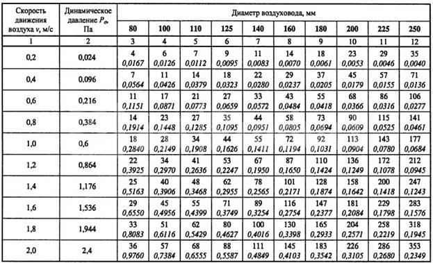

It is necessary to know the speed of air movement in order to calculate not only the volume of gas mixture supply, but also to determine the dynamic pressure on the channel walls, friction and resistance losses, etc.
Some useful tips and notes
As can be understood from the formula (or when carrying out practical calculations on calculators), the air speed increases with a decrease in the size of the pipe. There are a number of benefits to be derived from this fact:
- there will be no losses or the need to lay an additional ventilation pipeline to ensure the necessary air flow, if the dimensions of the room do not allow large ducts to be laid;
- smaller pipelines can be laid, which in most cases is easier and more convenient;
- the smaller the diameter of the channel, the cheaper its cost, the price of additional elements (flaps, valves) will also decrease;
- the smaller size of the pipes expands the installation possibilities, they can be positioned as needed, with little or no adjustment to external constraints.
However, when laying air ducts of a smaller diameter, it must be remembered that with an increase in air speed, the dynamic pressure on the pipe walls increases, and the resistance of the system also increases, respectively, a more powerful fan and additional costs will be required. Therefore, before installation, it is necessary to carefully carry out all the calculations so that the savings do not turn into high costs or even losses, because. a building that does not comply with SNiP standards may not be allowed to operate.
The importance of air exchange
Depending on the size of the room, the air exchange rate should be different.
The task of any ventilation is to provide an optimal microclimate, humidity level and air temperature in the room. These indicators affect the comfortable well-being of a person during the work process and rest.
Poor ventilation leads to the growth of bacteria that cause respiratory infections. Food items begin to spoil quickly.The increased level of humidity provokes the appearance of fungus and mold on the walls and furniture.
Fresh air can enter the room in a natural way, but it is possible to achieve compliance with all sanitary and hygienic indicators only when a high-quality ventilation system is in operation. It should be calculated for each room separately, taking into account the composition and volume of air, design features.
For small private houses and apartments, it is enough to equip mines with natural air circulation. But for industrial premises, large houses, additional equipment is required in the form of fans that provide forced circulation.
When planning a building for an enterprise or public institution, the following factors must be taken into account:
- high-quality ventilation should be in every room;
- it is necessary that the composition of the air complies with all approved standards;
- enterprises require the installation of additional equipment that will regulate the air velocity in the duct;
- for the kitchen and bedroom it is necessary to install different types of ventilation.
We start designing
The calculation of the structure is complicated by the fact that it is necessary to take into account a number of indirect factors affecting the efficiency of the system. Engineers take into account the location of the constituent components, their features, etc.
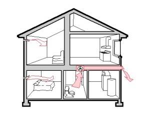
It is important to take into account the location of the premises even at the stage of designing a house. It depends on how effective ventilation will be.
The ideal option is such an arrangement in which the pipe is opposite the window. This approach is recommended in all rooms.If TISE technology is implemented, then the ventilation pipe is mounted in the walls. Her position is vertical. In this case, air enters each room.
Calculation algorithm
When designing, setting up or modifying an existing ventilation system, duct calculations are required. This is necessary in order to correctly determine its parameters, taking into account the optimal characteristics of performance and noise in actual conditions.
When performing calculations, the results of measuring the flow rate and air velocity in the air duct are of great importance.
Air consumption - the volume of air mass entering the ventilation system per unit of time. As a rule, this indicator is measured in m³ / h.
Movement speed is a value that shows how fast air moves in the ventilation system. This indicator is measured in m/s.
If these two indicators are known, the area of circular and rectangular sections, as well as the pressure required to overcome local resistance or friction, can be calculated.
When drawing up a diagram, you need to choose the angle of view from that facade of the building, which is located in the lower part of the layout. Air ducts are displayed as solid thick lines
The most commonly used calculation algorithm is:
- Drawing up an axonometric diagram in which all elements are listed.
- Based on this scheme, the length of each channel is calculated.
- The air flow is measured.
- The flow rate and pressure in each section of the system is determined.
- Friction losses are calculated.
- Using the required coefficient, the pressure loss is calculated when overcoming local resistance.
When performing calculations on each section of the air distribution network, different results are obtained. All data must be equalized using diaphragms with the branch of the greatest resistance.
Calculation of cross-sectional area and diameter
The correct calculation of the area of circular and rectangular sections is very important. An unsuitable section size will not allow for the desired air balance.
Too large a duct will take up a lot of space and reduce the effective area of the room. If the channel size is too small, drafts will occur as the flow pressure increases.
In order to calculate the required cross-sectional area (S), you need to know the values \u200b\u200bof the flow rate and air velocity.
For calculations, the following formula is used:
S=L/3600*V,
while L is the air flow rate (m³/h), and V is its speed (m/s);
Using the following formula, you can calculate the duct diameter (D):
D = 1000*√(4*S/π), where
S - cross-sectional area (m²);
π - 3.14.
If it is planned to install rectangular rather than round ducts, instead of the diameter, determine the required length / width of the air duct.
All obtained values are compared with GOST standards and products are selected that are closest in diameter or cross-sectional area
When choosing such an air duct, an approximate cross section is taken into account. The principle used is a*b ≈ S, where a is the length, b is the width, and S is the sectional area.


According to the regulations, the ratio of width and length should not exceed 1:3. You should also refer to the standard size table provided by the manufacturer.
The most common dimensions of rectangular channels are: the minimum dimensions are 0.1 m x 0.15 m, the maximum dimensions are 2 m x 2 m.The advantage of round ducts is that they have less resistance and therefore less noise during operation.
Calculation of pressure loss on resistance
As air moves through the line, resistance is created. To overcome it, the air handling unit fan creates pressure, which is measured in Pascals (Pa).
Pressure loss can be reduced by increasing the cross section of the duct. In this case, approximately the same flow rate in the network can be provided.
In order to select a suitable air handling unit with a fan of the required capacity, it is necessary to calculate the pressure drop across overcoming local resistance.
This formula applies:
P=R*L+Ei*V2*Y/2, where
R- specific pressure loss friction on a specific section of the duct;
L is the length of the section (m);
Еi is the total coefficient of local loss;
V is the air speed (m/s);
Y – air density (kg/m3).
The R values are determined by the standards. Also, this indicator can be calculated.
If the duct is round, the friction pressure loss (R) is calculated as follows:
R = (X*D/B) * (V*V*Y)/2g, where
X - coefficient. friction resistance;
L - length (m);
D – diameter (m);
V is the air speed (m/s) and Y is its density (kg/m³);
g - 9.8 m / s².
If the section is not round, but rectangular, it is necessary to substitute an alternative diameter in the formula, equal to D \u003d 2AB / (A + B), where A and B are the sides.
The need for good ventilation
First you need to determine why it is important to ensure that air enters the room through the ventilation ducts. According to building and hygiene standards, every industrial or private facility must have a high-quality ventilation system.
The main task of such a system is to provide an optimal microclimate, air temperature and humidity level, so that a person can feel comfortable while working or relaxing. This is possible only when the air is not too warm, full of various pollutants and has a fairly high level of moisture.
According to building and hygiene standards, every industrial or private facility must have a high-quality ventilation system. The main task of such a system is to provide an optimal microclimate, air temperature and humidity level, so that a person can feel comfortable while working or relaxing. This is possible only when the air is not too warm, full of various pollutants and has a fairly high level of moisture.
Poor ventilation contributes to the appearance of infectious diseases and pathologies of the respiratory tract. In addition, food spoils faster. If the air has a very high percentage of moisture, then fungus can form on the walls, which can later go to the furniture.


Fresh air can get into the room in many ways, but its main source is still a well-installed ventilation system. At the same time, in each individual room, it should be calculated according to its design features, air composition and volume.
It is worth noting that for a private house or apartment of small size, it will be enough to install shafts with natural air circulation. For large cottages or production workshops, it is necessary to install additional equipment, fans for forced circulation of air masses.
When planning a building of any enterprise, workshops or large public institutions, it is necessary to follow the following rules:
- in each room or room, a high-quality ventilation system is required;
- the composition of the air must meet all established standards;
- in enterprises, additional equipment should be installed with which it is possible to regulate the rate of air exchange, and for private use, less powerful fans should be installed if natural ventilation cannot cope;
- in different rooms (kitchen, bathroom, bedroom) it is required to install different types of ventilation systems.
You should also design the system in such a way that the air is clean in the place where it will be taken. Otherwise, polluted air can get into the ventilation shafts and then into the rooms.
During the drafting of the ventilation project, after the required volume of air is calculated, marks are made where ventilation shafts, air conditioners, air ducts and other components should be located. This applies to both private cottages and multi-storey buildings.
The efficiency of ventilation in general will depend on the size of the mines. The rules that must be observed for the required volume are indicated in the sanitary documentation and SNiP norms. The speed of the air in the duct in them is also provided.