- General principles of operation of walk-through switches
- Kinds
- Overhead
- Internal
- How does a two-button switch work?
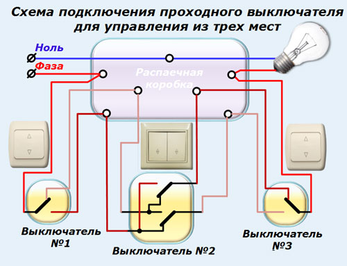
- Scheme of three-key equipment
- Elements and components of the connection diagram
- Step by step installation instructions
- Comments:
- Leave a comment Cancel reply
- How to connect a pass-through switch: a video connection diagram will help you do all the work on your own
- Scheme of connecting a pass-through switch from 3 places: a detailed video of the work
- Scheme of connecting a pass-through switch from 4 places: current information
- 3-point wiring diagram through switch
- Wiring diagram with two lighting fixtures
- What mistakes can be made?
- Triple pass switch - wiring diagram
- Wiring diagram for circuit breakers from multiple zones
- Conclusions and useful video on the topic
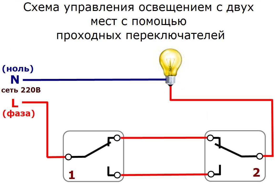
General principles of operation of walk-through switches
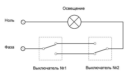
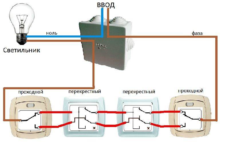
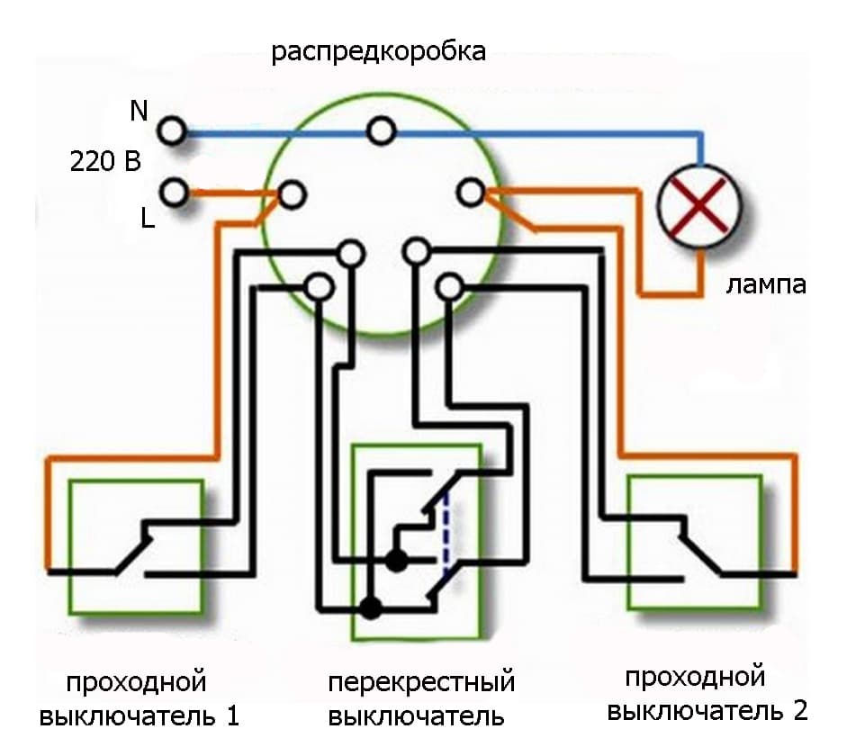
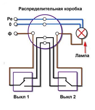
To understand how the circuit works, consider its main elements using the example of two switching points (the most common):
- Instead of a switch in the classical sense (a device that opens the circuit), a switch is used. That is, on the one hand there are two contacts, and on the other - one. In this case, the phase (which is supplied to the light point) is not switched to one of the outputs, but, on the contrary, is switched on to both contacts, on the one hand.
- The circuit will be closed when both switches are in the same position. That is, either both keys are up, or both keys are down. One of the switches is conditionally considered an input, a phase supply wire comes to it. Depending on the position of the key, voltage is applied to one of the output contacts, which in turn are connected to the input pair of the second switch (output). The diagram clearly shows in which case the circuit is closed, and in which it is open.
- In practice, it works like this: you go to the beginning of the corridor, turn on the lighting. Having passed to the end, you turn off the light with the help of the second switch. Moving in the opposite direction, you simply move the keys to a different position, keeping the same algorithm.
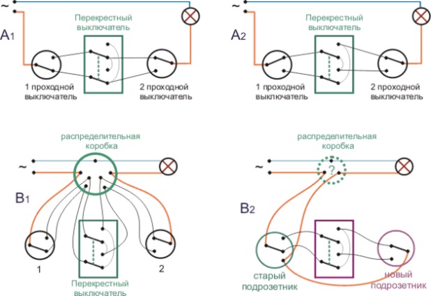
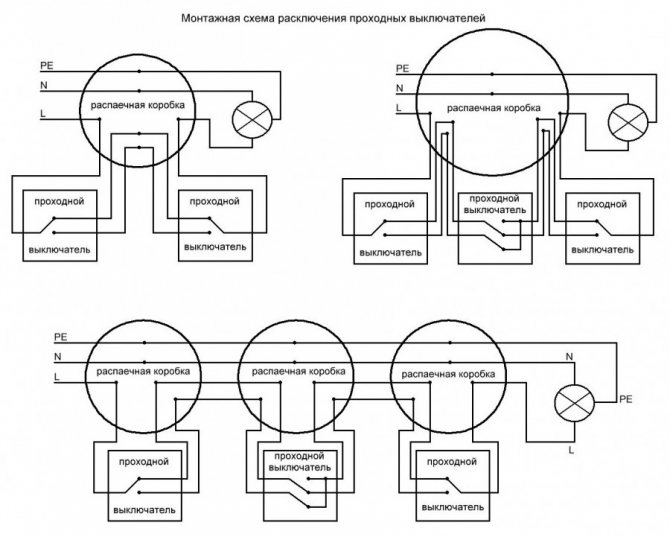
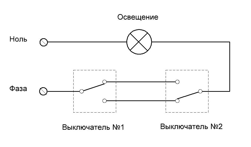
The previous diagram showed how to organize a circuit using a junction box. This is the correct way, but it leads to cable overrun: the lines are duplicated, additional terminal groups appear. Switches can be connected directly if the room configuration allows.
The system works exactly the same, only you have to run a horizontal wire between the switches. In this case, it is not necessary to mount a junction box and lay "extra" wires.
Kinds
Devices are divided into 2 types based on the attachment point:
Overhead
They are installed directly on the wall and can be used both in a hidden wiring system and when laying cables openly.
Internal
Designed for installation in a socket box located in the wall. Connect to internal wiring only.
The latter are used as a more ergonomic option. The entire body of the switch is hidden inside the wall, and a decorative frame and keys are visible from the outside.Overhead models are easier to install, because they do not require the creation of a recess in the wall.
They are used when it is impractical to carry out major repairs with the replacement of wiring. Both models of the same type and different types can work in pairs.
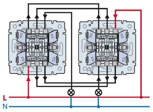
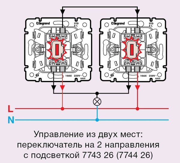
How does a two-button switch work?
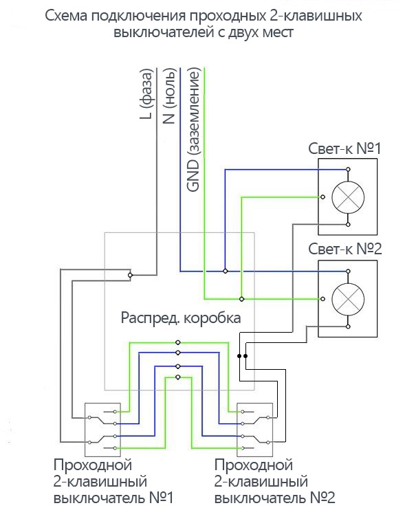
The equipment has a total of 12 pins, 6 for each double switch (2 inputs, 4 outputs), therefore, to connect equipment of this type, you need to take 3 wires for each key of the device.
Switch Diagram:
 Switch circuit
- the device consists of a pair of independent contacts;
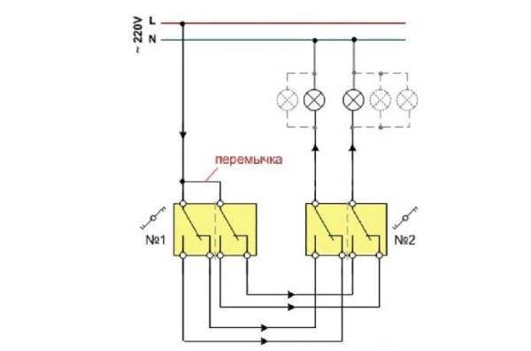
- the upper contacts of the device N1 and N2 are switched to the lower ones by pressing the keys. The elements are connected by a jumper;
- the second contact of the right switch, shown in the diagram, is aligned with the phase;
- the contacts of the left mechanism do not intersect with each other, joining two different sources;
- The 4 cross contacts are combined in pairs.
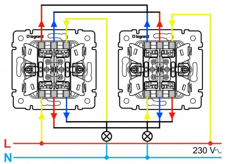
The installation of a two-gang switch is carried out as follows:
- A pair of double mechanisms is installed in the sockets in selected areas.
- For each light source, a separate three-core cable is placed in the socket, the cores of which are cleaned of insulation by about 1 centimeter.
- In the diagram, the cable cores are designated as L (phase), N (working zero), ground (protective).
- The device is equipped with markings, which simplifies the task of connecting wires to the switch terminals. The wires are connected to the terminals in pairs.
- The bundle of wires is neatly placed in the socket, after which the switch mechanism, frame and cover of the protective housing are installed.
What the marking looks like:
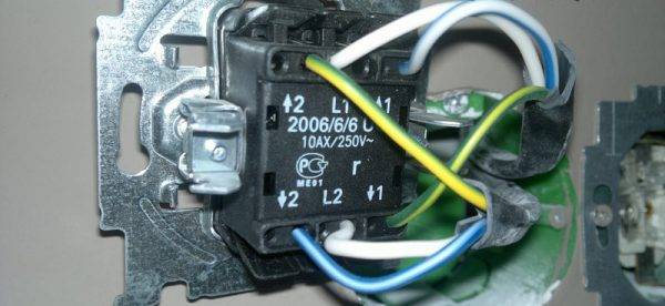 Two-key switch marking
Connection diagram example:
 Connection diagrams
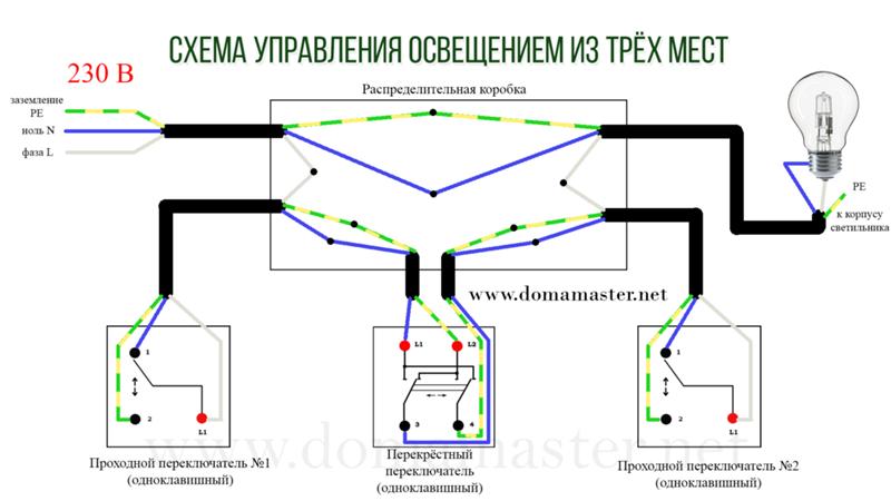
To facilitate the work process, it is recommended to select wires of a certain light. There is a color marking of wires for Russia and other CIS countries. Also on it, a beginner can learn to distinguish between cables. According to the Russian marking for the “earth”, yellow and green colors are used, the neutral cable is usually marked in blue. The phase can be red, black or grey.

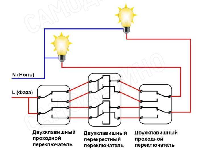


Scheme of three-key equipment
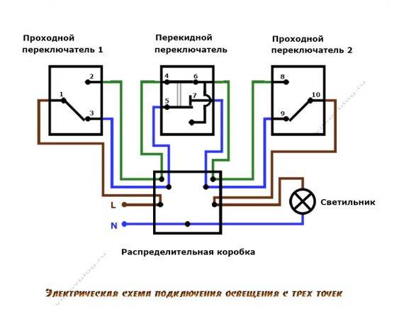
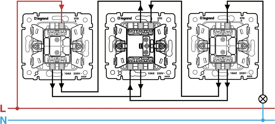
When installing a triple device, intermediate (cross) switches are used, which are connected between the two side elements.
 Scheme of three-key equipment
This switch has two inputs and outputs. The cross element can translate both contacts at the same time.
Triple equipment assembly process:
- Ground and zero are connected to a light source.
- The phase is connected to the input of one of a pair of through structures (with three inputs).
- A free wire of the light source is connected to the input of another switch.
- Two outputs of one element having three contacts are combined with the input of a cross device (with two pairs of outputs).
- Two outputs of the pair mechanism (with three contacts) are combined with another pair of terminals of the next switch (with four inputs).
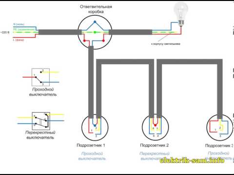
Elements and components of the connection diagram
The structure of this circuit includes a junction box, lighting fixtures, switches and wires. Not only conventional incandescent lamps, but also various types of LED and energy-saving lamps are used as light sources. The switches used in the circuit are divided into through and cross.In turn, pass-through switches can be toggle, redundant or ladder. Their installation takes much longer than conventional switches.
The classic scheme for connecting a three-way switch requires the use of two through switches and one cross. The appearance of duplicating devices is almost the same as that of a single-key device. In any position of the keys of such a switch, the connection of the electrical circuit is not interrupted, only the contacts are switched. The switching mechanism in the walk-through switches is located in the center of the contacts.
Devices can be one- or two-key. In the second case, two devices are combined into one with six contacts. The circuits often use single-key light switches that do not differ from each other. Each of them is equipped with three contacts. At the first device, a phase wire is connected to one contact, and intermediate wires to the other two. At the third switch, on the contrary, an intermediate wire is connected to one contact, and output phase lines to the other two.
The switch installed in the middle acts as a cross switch. It has four contacts, from which two wires go to each toggle switch No. 1 and No. 3. If the intermediate electrical wire is shorted on any of the toggle devices, the light will turn on. When the state of the key changes, the circuit breaks and the light goes out. If there is a need to increase the number of light control points, it is enough to add the required number of cross switches to the existing circuit.
For the correct installation of the control system, it is necessary to follow certain recommendations. If the room already has an electrical network, then separate open or closed networks must be connected to the backup switches. In the second case, strobes must be made in the walls. You may need a special tool and building plaster to attach the corrugated pipe. Laying of new lines is carried out with a three- or four-wire cable.
Step by step installation instructions
- Disconnect the electricity in the room.
- Determine where the wires are, so as not to damage them.
- Designate the future location of the junction box.
- Install the mounting box.
- Laying of electrical cables. It is better to take a 3- or 4-core cable. For changeover devices, a three-wire is needed. With the help of one core, a phase supply or a lamp will be connected. Two cores are connected to intermediate wires. A crossover device requires a four-core cable - two cores for each switch. Two will lead to the first, and the remaining two to the second.
The ends of all cables are led into the junction box and connected with terminals. And zero goes to the lamp.
To equip a walk-through switch with 3-position control, you must have skills and an accurate wiring diagram. Its presence makes it possible to carry out the correct and high-quality lighting system. And on its basis, you can easily create more complex illumination schemes.
Comments:
Veda
Who has used this scheme? Has anyone worked
Vassa
From the point of view of electricians, nothing can not work here. Everything is clearly and correctly described. Another thing is that I have not seen devices of this type on sale.Under the order, it is quite possible that they will be, but I didn’t see it in the store
Oleg
Are there other uses for such switches other than in a long hallway?
Slavon
It seems to me that in the corridor just this scheme is of little use. A person usually needs to reach the end of the corridor, and then turn off the light. Most likely, it is better to use such a switch connection scheme in the bedroom, where each side of the bed has its own switch to turn on / off the main lighting and another one is located at the entrance. In this case, from all three points you can turn on / off the light


Alex
I once redid the work of an electrician clown, who tried to accommodate all the connections from such a switch in a conventional socket box. As a result, the switch mounted in it squeezed all the wires. In general, I do not advise anyone to repeat this experience. Wiring for walk-through switches should be done only in the distribution box!
Andrew
With the help of pass-through (limit, 3-pin switches) switches, it is possible to decide on and off only for two posts (places). And if you need more than two on / off posts, then you need: cross or intermediate (at least 4-pin, switches) switches.
ANDREW
The electrician threw three-wire wires, I don’t know that four wires will be needed ... Is it really possible to connect somehow so that the switch works as expected or will I have to look for other models?
Leave a comment Cancel reply

What features does the Legrand switch have and how can I connect it?

We make holes for the outlet in concrete and tiles ourselves

How to choose and connect a differential machine

Proper and convenient installation of sockets in the apartment
How to connect a pass-through switch: a video connection diagram will help you do all the work on your own
It can be quite difficult, even with a diagram, to install a pass-through switch in the absence of a specialized education. In this case, master classes recorded on video can come to the rescue. They describe in detail how to connect a pass-through switch, and in what sequence the work should be done.
Before you start viewing, you should decide on the type of the selected device. The order of connecting the cross switch will have a number of significant differences, which you should familiarize yourself with in advance.
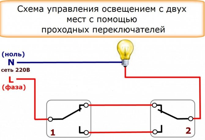
If we are talking about a pass-through switch, a 2-point connection scheme is the simplest option. This is the minimum number of devices that can be connected to the system so that the user can turn one lamp on or off. Otherwise, it will be a normal switch.
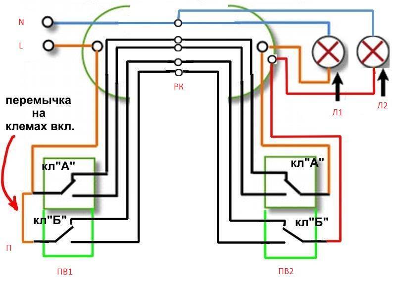
When installing a two-gang pass-through switch, the connection scheme from two places can be implemented for two loads. This is quite convenient if the room is long, and it is necessary to provide for the installation of several lamps for more uniform illumination of the surrounding space. In this case, it will be possible to regulate the intensity of the lighting of the room, deciding how many lamps will be turned on at a certain point in time.
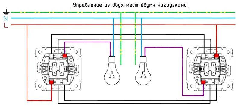 Two-way switch circuit capable of controlling two loads
The following video will help you understand the switch connection diagram from two places in more detail:
 Watch this video on YouTube
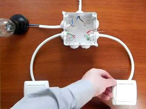
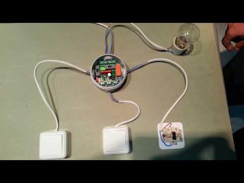
It clearly shows how to connect the wires in the junction box so that there are no difficulties during operation. Following the recommendations of a specialist, it is possible to perform the required amount of work qualitatively and at minimal cost.
Scheme of connecting a pass-through switch from 3 places: a detailed video of the work
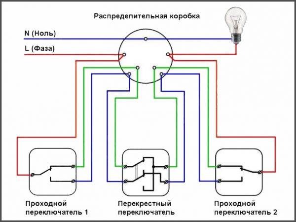
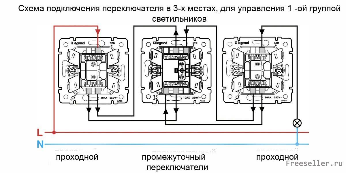
The connection diagram of the 3-point pass-through switch can be called conditional. In this case, we are talking about the inclusion of a cross switch in the circuit, acting as an additional link. As a rule, installation work does not cause any special difficulties. The cross device is connected between the feedthroughs.


You can learn more about the connection diagram of the 3-place pass-through switches by watching the following video:
 Watch this video on YouTube
Detailed instructions will allow you to understand the order of work, as well as let you know what tool you need for installation.
 Watch this video on YouTube
Scheme of connecting a pass-through switch from 4 places: current information
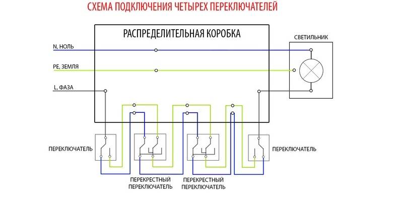
If the area of the room is large enough, two or three switches may not be enough. You will have to travel a long distance each time to turn the lights on or off. In this case, it will be possible to use the 4-point switch connection diagram. In this case, two additional cross devices are introduced into the system.
 Connection diagram of a lamp to four switches
A four-point connection scheme will be relevant for a multi-storey building. In this case, the same lamp can be controlled from each floor and, if desired, from the basement.
 Watch this video on YouTube
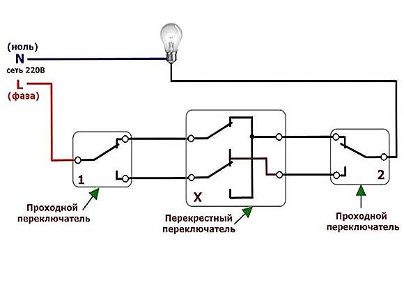
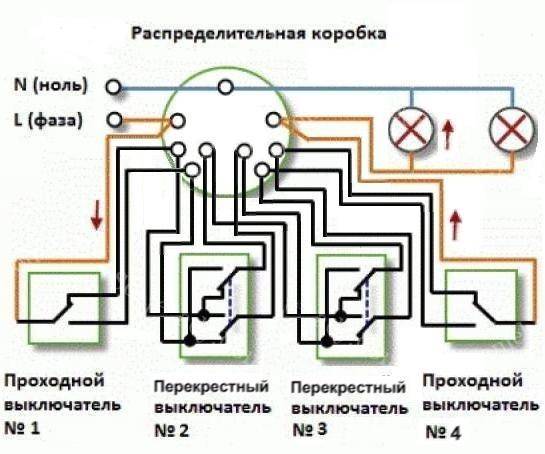
3-point wiring diagram through switch
In this scheme, the lamp is connected with one wire to the neutral wire of the network, the second to the common wire of the first pass-through switch. Two wires from the first pass switch are connected to a pair of contacts on the cross one. The remaining two free contacts are connected to the second pass-through switch. The last contact in the second feed-through switch is connected to the phase wire.
The connection diagram for 3 two-gang switches is practically the same as the previous diagram. Its main difference is the use of two 2-key walk-through switches of one 2-key cross.
The advantage of this scheme lies in the independent control of two independent light sources (lamps, fixtures). There are also more complex circuits, with five or more switching points, but they are most often used in industry and their use in everyday life is not advisable.
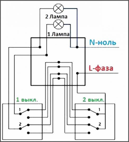
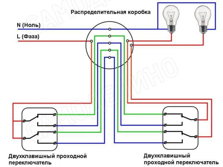
Wiring diagram with two lighting fixtures
Of course, the first option is popular and easy to perform, so it is widely used. However, in a room there are two or three lamps or several light bulbs that are divided into groups, so the standard scheme is no longer suitable here.
If you want to install with two groups of lighting fixtures, you will need to purchase a switch with two keys, where there are six clips.
 Switch with two keys, where there are six clamps
Otherwise, in terms of installation method and equipment, this scheme is not much different from the previous one. However, more wiring will have to be laid here.Therefore, in order to reduce the cost of purchasing wires, it is recommended to connect the power conductor to the first switch in the chain with a jumper. After all, otherwise you will have to lay separate conductors from the distribution box.
What mistakes can be made?
Naturally, with the inability to read the installation diagram of the Lezard double-gang switches, you can make a lot of mistakes. And the very first happens when looking for a common contact. By mistake, some people think that the common terminal is the one that is located separately from the other two. And it's not like that at all. Of course, on some models such a "chip" can work, but this happens quite rarely.
And if you assemble the circuit with an error, the switches will not work correctly, no matter how many times you click them
The common contact can be located anywhere, so it is important to find it, focusing on the diagram or instrument readings. Quite often, such problems arise when installing or replacing pass-through switches from different manufacturers. We looked at the information one at a time, connected it correctly, and the second turned out to be from another manufacturer
And it was connected according to the same scheme, but it does not work. To restore functionality, you need to find a common contact and connect all the wires correctly. This step is the main one, how the whole system will work in the future directly depends on it. There is no need to focus on chance, it is better to make sure several times that the contacts are correctly defined. And in order not to forget, you can mark them with a marker. Thus, of course, so that these marks are not visible from the outside


We looked at the information one at a time, connected it correctly, and the second turned out to be from another manufacturer. And it was connected according to the same scheme, but it does not work. To restore functionality, you need to find a common contact and connect all the wires correctly. This step is the main one, how the whole system will work in the future directly depends on it. There is no need to focus on chance, it is better to make sure several times that the contacts are correctly defined. And in order not to forget, you can mark them with a marker. Thus, of course, so that these marks are not visible from the outside.
But it also happens that the device that you use is not a pass-through
Therefore, when buying, you need to pay attention to what type of device is a pass-through or a regular two-key one. It is also worth mentioning the incorrect connection of cross devices. Some electricians put the wires from the first switch on the contacts located at the top
And from the second switch - to the contacts below. But you need to do it a little differently - connect all the wires to the device crosswise. Only in this case, the whole structure will be able to function correctly.
Some electricians put the wires from the first switch on the contacts located at the top. And from the second switch - to the contacts below. But you need to do it a little differently - connect all the wires to the device crosswise. Only in this case, the whole structure will be able to function correctly.
Triple pass switch - wiring diagram
The cross switch has the following functional load in the circuit:
- a transistor device that does not interact with a pair of other lighting switches;
- an independent device that opens the circuit and ensures the operability of part of the lighting devices.
If a pass-through switch installed for a pair of points involves the use of a three-core electrical cable, then five contacts are used to equip the third point.
In this case, a pair of contacts is connected to one of the mid-flight switches, and another pair is connected to the second device. The free device is used as a transit device.
It is important to remember that the transit contact present in the connection diagram is mandatory, as it is used to connect to the electrical circuit and ensure the operability of the third connection point.
Wiring diagram for circuit breakers from multiple zones
The cross switch is mounted at a time with two passages, while almost all connections are important to be made through the junction box. The switching device is installed so that it becomes a link between the rest of the switches: two wires of each electrical product are inserted into it, and then output. It is easy to understand this matter: on the wrong side of the cross switch, they indicate where the input and output from the terminals are located
It is easy to understand this matter: on the wrong side of the cross switch, they indicate where the input and output from the terminals are located.
Connecting a cross switch is carried out in several steps:
- develop an electrical wiring diagram;
- drill the channels necessary for laying the wiring;
-
a junction box is inserted into the wall of such a size that it would allow more than 7 connections to be created and many wires to be passed through it;
- the lever of the electrical panel cuts off the supply of electric current to the installation area of the switching device;
- a cable is pulled from the junction box to the shield, lighting fixtures and switches;
- a zero core is brought to the contacts of the lamps;
-
a phase conductor is connected to the contact of the first pass-through switch;
- the system is supplemented with paired wires going from one switch to another;
- the contacts of the last cross switch are connected to the lighting fixtures through the junction box.
Conclusions and useful video on the topic
How the application of schemes for connecting pass-through switches from several places occurs in practice can be found in the videos presented.
The order of connection of the cores in the junction box:


Connection instruction from 2 places:
The appearance and introduction of devices of this kind in electrical networks may not be so significant, but still affected the ease of use. Moreover, solutions based on walk-through switches actually lead to energy savings.
Meanwhile, the improvement of devices does not stop. Periodically, new developments appear, for example, similar to touch switches.
Do you have something to add, or have questions about connecting a pass-through switch? You can leave comments on the publication, participate in discussions and share your own experience in arranging the power grid. The contact form is in the bottom block.


