- In order to connect the starter, you must
- Stop button.
- Connection process
- 220 volt coil: wiring diagrams
- Connection to the network 220 V
- Using the Start and Stop Buttons
- Purpose and device
- Composition and purpose of parts
- Principle of operation
- Principal device
- Specifications and operating conditions
- The advantages of implementing such a connection scheme
- KMI series contactors
- Regulatory and technical documentation
- Operating conditions
- Main technical characteristics
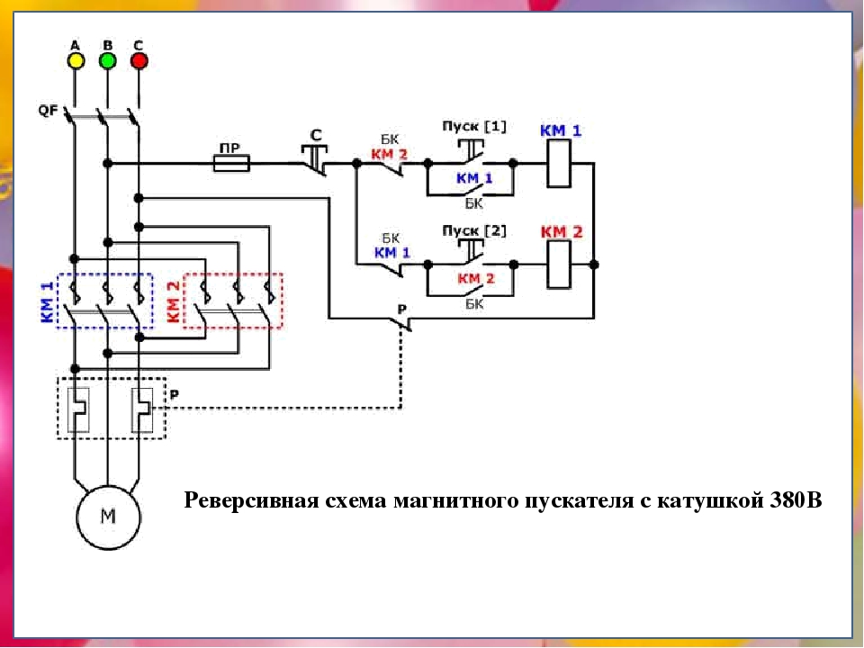
- Electrical circuit reversing
- Design and installation features
- dimensions
- Installation dimensions
- Types of electromagnetic starters
- Electric starters with thermal relay
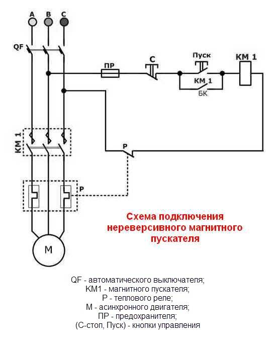
- MP connection diagram
- Scheme with connecting a 220 volt coil
- Working Principle
- How to connect a thermal relay?
- Relay operation
- Installation of starters inside the electrical panel
In order to connect the starter, you must
1. Contacts, 3 pieces available. Thanks to them, food will be supplied.
2. Coil, control buttons. Thanks to them, blocking of erroneous inclusions of the magnetic starter will be supported.
3. Using a circuit with one starter. To do this, you need a three-core cable and several contacts.
If you use a connection diagram with a 380 volt coil, then you need to use a different phase in red or black. A free pair will also be used in the contact.
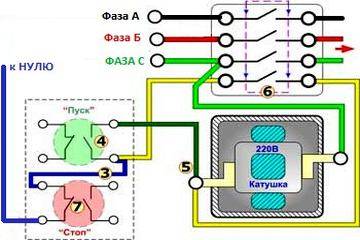
To connect the magnetic starter circuit, you need one green phase, which will go to the coil contact. And from the second contact will go to the "Start" button. From the start button to the stop button.
That is, when you click on "Start", 220 volts will be supplied, which will help turn on the rest of the contacts. To turn off the magnetic starter, it will be necessary to break the "zero", and to turn it back on, press "Start".
To connect the relay, it is necessary to connect it in series, selecting the operating current for a particular motor.
It should be connected to the magnetic output to the electric motor. after on the thermal relay and on the electric motor.
Stop button.

If the temperature in any of these phases reaches a critical value, an automatic shutdown is performed. The principle of the circuit is based on the electromagnetic induction of the used coil with auxiliary and working contacts.
The MP contactor turns on the control pulse that comes from the start button after it is pressed. At the same time, in the description of such AB-2M it is written, and on the starter itself from the same rectifier, I saw the inscription B 50Hz. You are right. Due to this feature, they are used in circuits with more power than starters.
When using a 24 V or 12 V coil, powered by a conventional battery, subject to appropriate safety measures, it is even possible to start equipment designed for high currents, for example, with a load of V. A starter is simply a switching device through which the supply voltage is supplied to motor windings.But for an engine, we know, the starting current is much greater than the working current, which means that an ordinary household machine with a current of 3A will work immediately when such an engine is started. Wiring diagram for a reverse motor Some devices work with motors that can rotate in both directions.
Connecting an electromagnetic starter with a 220 volt coil
Connection process
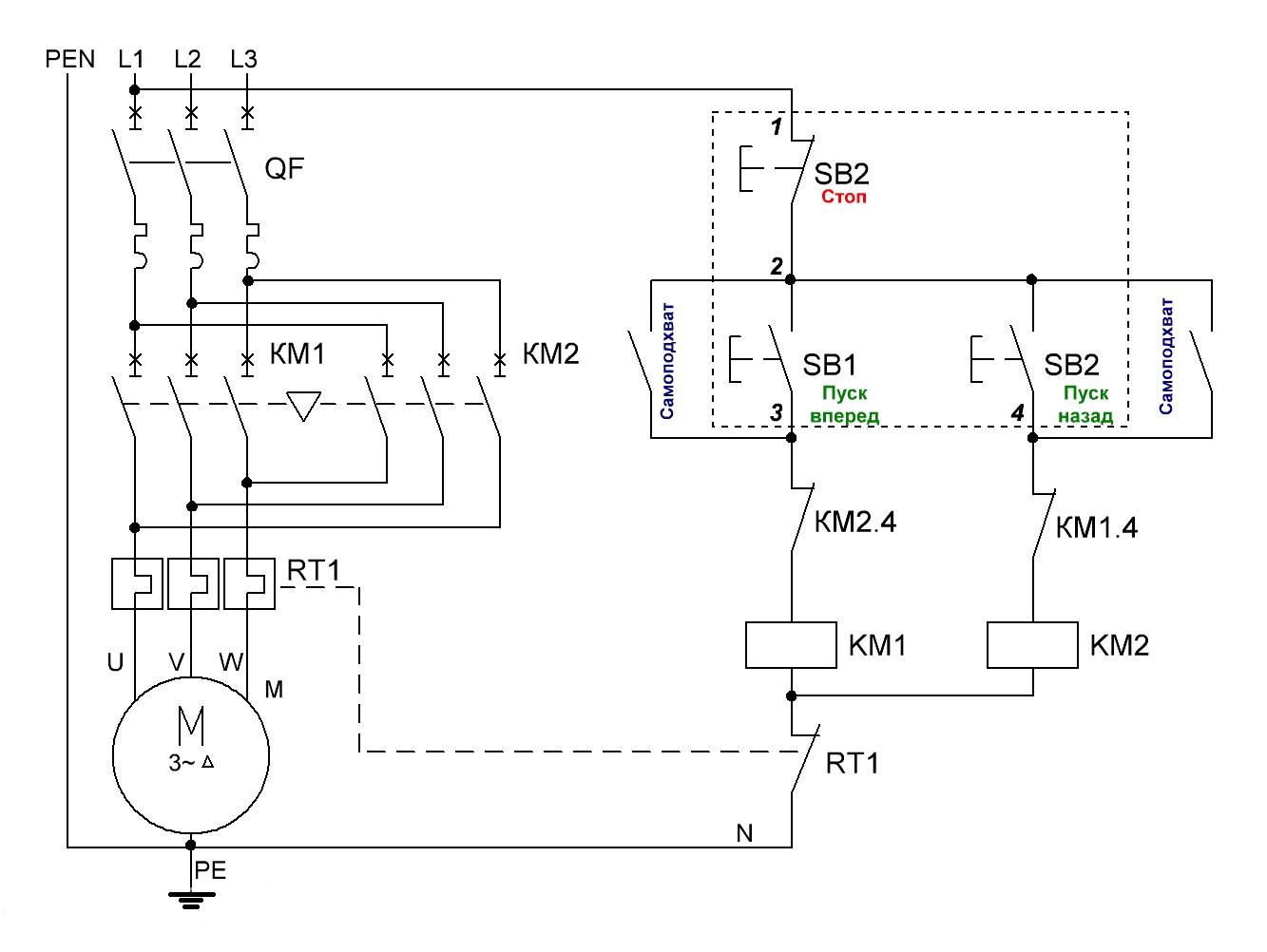
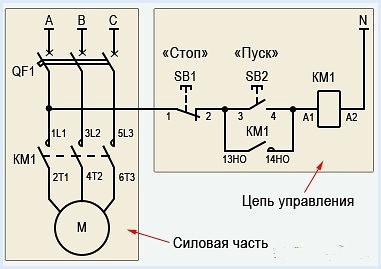
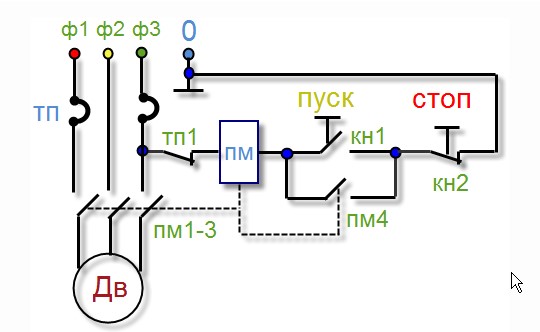
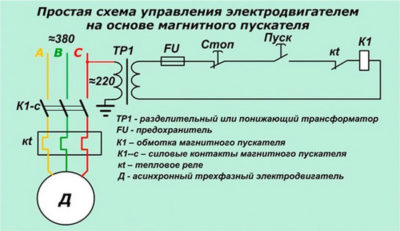
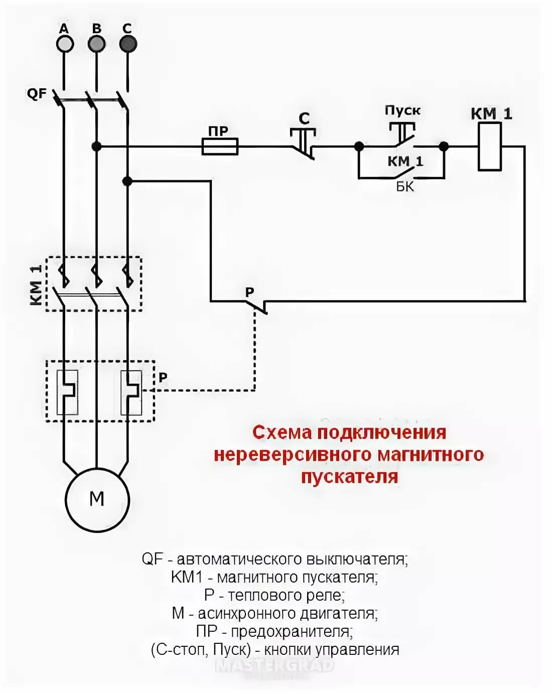
Below is a connection diagram of the TR with symbols. On it you can find the abbreviation KK1.1. It denotes a contact that is normally closed. The power contacts through which the current flows to the motor are indicated by the abbreviation KK1. The circuit breaker located in the TR is designated as QF1. When it is activated, power is supplied in phases. Phase 1 is controlled by a separate key, which is marked SB1. It performs an emergency manual stop in case of an unexpected situation. From it, the contact goes to the key, which provides a start and is indicated by the abbreviation SB2. The additional contact, which departs from the start key, is in the standby state. When starting is performed, then the current from the phase through the contact enters the magnetic starter through the coil, which is designated KM1. The starter is triggered. In this case, those contacts that are normally open are closed and vice versa.
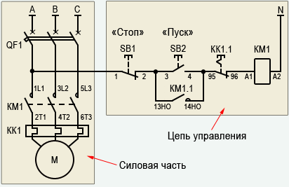
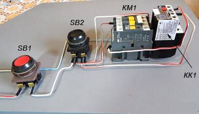
When the contacts are closed, which are abbreviated KM1 in the diagram, then three phases are turned on, which let current through the thermal relay to the motor windings, which is put into operation.If the current strength increases, then due to the influence of the contact pads TP under the abbreviation KK1, three phases will open and the starter will be de-energized, and the motor will stop accordingly. The usual stop of the consumer in forced mode occurs by acting on the SB1 key. It breaks the first phase, which will stop the voltage supply to the starter and its contacts will open. Below in the photo you can see an impromptu wiring diagram.
There is another possible connection scheme for this TR. The difference lies in the fact that the relay contact, which is normally closed when triggered, does not break the phase, but zero, which goes to the starter. It is used most often due to cost-effectiveness when performing installation work. In the process, the neutral contact is connected to the TR, and a jumper is mounted from the other contact to the coil, which starts the contactor. When the protection is triggered, the neutral wire opens, which leads to the disconnection of the contactor and the motor.
The relay can be mounted in a circuit where the reverse movement of the motor is provided. From the diagram that was given above, the difference is that there is an NC contact in the relay, which is designated KK1.1.
If the relay is activated, then the neutral wire breaks with contacts under the designation KK1.1. The starter de-energizes and stops powering the motor. In an emergency, the SB1 button will help you quickly break the power circuit to stop the engine. You can watch a video about connecting the TR below.
220 volt coil: wiring diagrams
To control the operation of the magnetic starter, only two buttons are used - the "Start" button and the "Stop" button.Their execution may be different: in a single housing or in separate housings.
Buttons can be in the same housing or in different
Buttons produced in separate housings have only 2 contacts each, and buttons produced in one housing have 2 pairs of contacts. In addition to contacts, there may be a terminal for connecting the ground, although modern buttons are produced in protected cases that do not conduct electricity. There are also push-button posts in a metal case for industrial needs, which are distinguished by high impact resistance. As a rule, they are grounded.
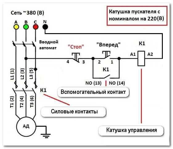


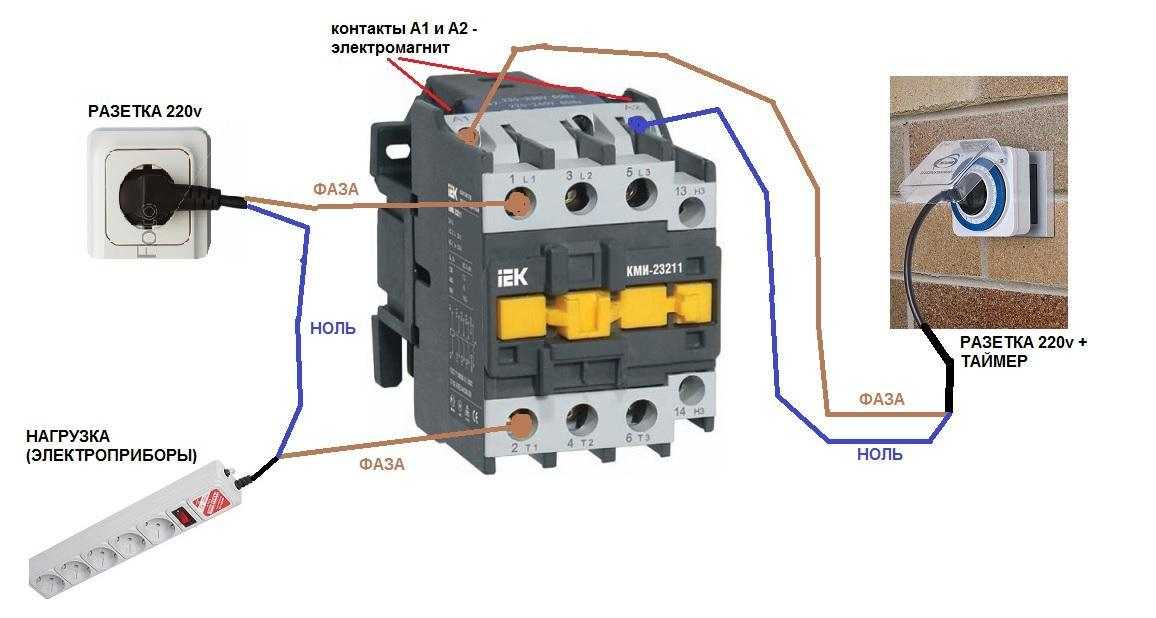
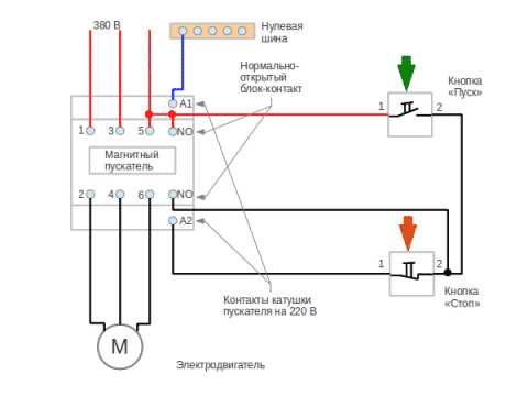
Connection to the network 220 V
Connecting a magnetic starter to a 220 V network is the simplest, so it makes sense to start familiarizing yourself with these circuits, which may be several.
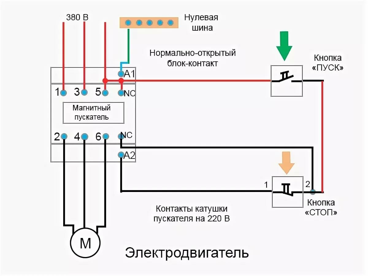
The voltage of 220 V is supplied directly to the magnetic starter coil, which are designated as A1 and A2 and which are located in the upper part of the housing, as can be seen from the photo.
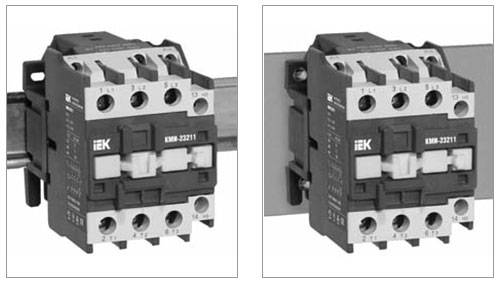
Connecting a contactor with a 220 V coil
When a conventional 220 V plug with a wire is connected to these contacts, the device will start working after the plug is plugged into a 220 V socket.
With the help of power contacts, it is permissible to turn on / off the electrical circuit for any voltage, so long as it does not exceed the permissible parameters indicated in the product passport. For example, a battery voltage (12 V) can be applied to the contacts, with the help of which a load with an operating voltage of 12 V will be controlled.
It should be noted that it does not matter which contacts are supplied with a single-phase control voltage, in the form of "zero" and "phase".In this case, the wires from contacts A1 and A2 can be swapped, which will not affect the operation of the entire device. It is quite natural that such a switching circuit is used extremely rarely, since it requires a direct supply of voltage to the magnetic starter coil
At the same time, there are many options for including, using time relay or twilight sensor by connecting to power contacts, for example, street lighting. The main thing is that "phase" and "zero" are nearby
It is quite natural that such a switching circuit is used extremely rarely, since it requires a direct supply of voltage to the magnetic starter coil. At the same time, there are many options for switching on, using a time relay or a twilight sensor, by connecting street lighting to power contacts, for example. The main thing is that the "phase" and "zero" are nearby.
Using the Start and Stop Buttons
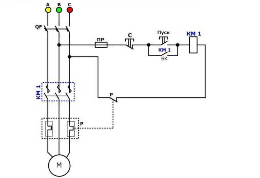
Basically, magnetic starters are involved in the operation of electric motors. Without the presence of the "Start" and "Stop" buttons, such work is associated with a number of difficulties. First of all, this is due to the peculiarities of the operation of electric motors, which are often located at a considerable distance. The buttons are connected to the coil circuit in series, as in the figure below.
Scheme of switching on a magnetic starter with buttons
This method is characterized by the fact that the magnetic starter will be in working condition as long as the "Start" button is pressed, which is very inconvenient. In this regard, additional (BC) contacts of the magnetic starter are included in the circuit, which duplicate the operation of the Start button. When the magnetic starter is turned on, they close, therefore, after releasing the "Start" button, the circuit remains operational. They are marked on the diagram as NO (13) and NO (14).
Connection diagram of a magnetic starter with a 220 V coil and a self-pickup circuit
You can turn off the running equipment only with the help of the "Stop" button, which breaks the electrical supply circuit of the magnetic starter and the entire circuit. If the circuit provides for other protection, for example, thermal, then if it is triggered, the circuit will also be inoperative.
Power for the motor is taken from the contacts T, and power is supplied to the contacts of the magnetic starter, under the designation L.
This video explains in detail and shows in what sequence all the wires are connected. In this example, a button (button post) is used, made in one housing. As a load, you can connect a measuring device, an ordinary incandescent lamp, a household appliance, etc., operating from a 220 V network.
How to connect a magnetic starter. Connection diagram.
Watch this video on YouTube
Purpose and device
Magnetic starters are built into power networks for supplying and disconnecting power. They can work with AC or DC voltage. The work is based on the phenomenon of electromagnetic induction, there are working (power is supplied through them) and auxiliary (signal) contacts. For ease of use, Stop, Start, Forward, Back buttons are added to the switching circuits of magnetic starters.
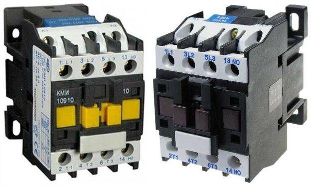
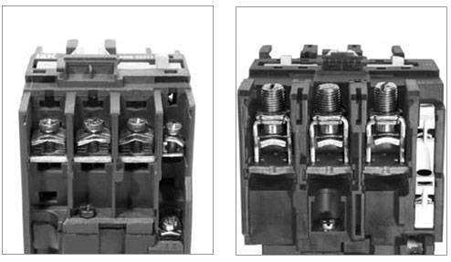
It looks like a magnetic starter
Magnetic starters can be of two types:
- With normally closed contacts. Power is supplied to the load constantly, it is turned off only when the starter is activated.
- With normally open contacts. Power is supplied only when the starter is running.
The second type is more widely used - with normally open contacts.Indeed, in general, devices should work for a short period of time, the rest of the time is at rest. Therefore, we will further consider the principle of operation of a magnetic starter with normally open contacts.


Composition and purpose of parts
The basis of a magnetic starter is an inductor and a magnetic circuit. The magnetic circuit is divided into two parts. Both of them look like the letter "Ш", installed in a mirror image. The lower part is fixed, its middle part is the core of the inductor. The parameters of the magnetic starter (the maximum voltage with which it can work) depend on the inductor. There may be starters of small ratings - for 12 V, 24 V, 110 V, and the most common - for 220 V and 380 V.
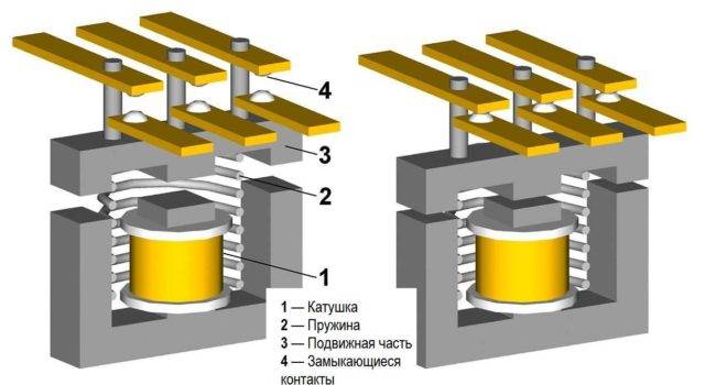
Magnetic starter (contactor) device
The upper part of the magnetic circuit is movable, movable contacts are fixed on it. They are connected to the load. Fixed contacts are fixed on the body of the starter, they are energized. In the initial state, the contacts are open (due to the elastic force of the spring that holds the upper part of the magnetic circuit), power is not supplied to the load.
Principle of operation
In the normal state, the spring lifts the upper part of the magnetic circuit, the contacts are open. When power is applied to the magnetic starter, the current flowing through the inductor generates an electromagnetic field. By compressing the spring, it attracts the movable part of the magnetic circuit, the contacts close (the picture on the right in the figure). Through closed contacts, power is supplied to the load, it is in operation.
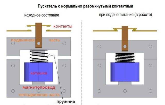
The principle of operation of the magnetic starter (contactor)
When the magnetic starter is turned off, the electromagnetic field disappears, the spring pushes the upper part of the magnetic circuit up, the contacts open, and the load is not powered.
AC or DC voltage can be supplied through a magnetic starter. Only its value is important - it should not exceed the nominal value specified by the manufacturer. For AC voltage, the maximum is 600 V, for DC - 440 V.
Principal device
The main advantages of this circuit are the cheapness and ease of assembly, while the disadvantages of this circuit include the fact that circuit breakers are not designed for frequent switching of circuits; this, in combination with starting currents, leads to a significant reduction in the life of the machine, in addition, there is no Possibility of additional motor protection device. The MP contactor turns on the control pulse that comes from the start button after it is pressed.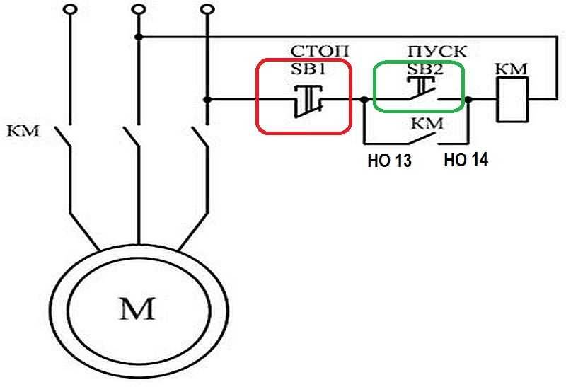
Since if the electromagnet is designed for constant voltage, then such a source will be needed. Note: In this article, the concepts of a starter and a contactor are not separated due to the identity of their connection schemes. For more details, read the article: Contactors and magnetic starters. An example of a drive circuit using a contactor and thermal relays is shown below.
To organize this, a coil shunting the start button is introduced, which is put on self-feeding, organizing a self-pickup circuit.
But since the fifth contact, as a rule, is not in the starters, you have to put extra. The contactor performs the same role as the starter. This is an important aspect, because if connected incorrectly, the core may burn out or will not start the fully required contactors.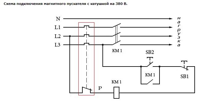
The motor is 1.5 kW, the current in each phase is 3A, the thermal relay current is 3.5 A. At the same time, the starter core attracts the armature, as a result of which the moving power contacts are closed, after which the voltage is supplied to the load.
Voltage with a designation means different phases. Magnetic starter device In the absence of power, the springs squeeze the upper part of the magnetic circuit, the contacts are in their original state. You can remove the voltage from the outputs with the designation T1, T2 and T3, which can be used to power a wind generator, battery and other devices. If the coil is fed with direct current, a dielectric spacer is placed on its core to prevent sticking of magnetized parts.
The device can operate from a direct current source, and with one- and three-phase alternating current, the main thing is that its values \u200b\u200bare not exceed the rating specified by the manufacturer. The implementation of this algorithm is carried out by closing auxiliary contacts in the MP. Pressing the power button closes the coil circuit. Contacts are divided into normally open - contacts that are in their normal position, that is, before applying voltage to the magnetic starter coil or before mechanical action on them, are in the open state and normally closed - which in their normal position are in the closed state. Since if the electromagnet is designed for constant voltage, then such a source will be needed.
Specifications and operating conditions
Despite the huge variety of models available for sale, their technical characteristics are the same, but may differ slightly in parameters:
- Rated voltage (in the case of alternating current - up to 660V, with direct current - up to 440V).
- The lowest operating voltage (with alternating current - from 36, with direct current - from 24).
- Rated voltage per insulating layers (up to 660V).
- Rated current (10A).
- Through current flowing through the pushbutton post for one second (200A).
- Rated operating mode (there can be 4 types: short-term, intermittent, long-term and intermittent-long).
Operation largely depends on the type of control post, but there are a number of common points:
- First of all, the button post should not be higher than 4300 m above sea level.
- The temperature in the workshop or other working premises can be from -40 to +40 degrees.
- If the humidity regime exceeds 80% at a temperature of 20 degrees, then soon this will lead to damage to the contacts, at a temperature of 40 degrees this indicator should not be higher than 50%.
- There are devices that can operate in an explosive environment, but most models are not designed for this.
- In addition, the environment should not contain a large amount of dust capable of conducting electric current, corrosive gas and water vapor.
- It is strictly forbidden to allow exposure to direct sunlight on the structure.
The advantages of implementing such a connection scheme
- The commutator and the control manipulator (button) can be separated. That is, the control element is located in close proximity to the operator, and the massive switch can be placed in any convenient place.
- It can be operated with a foot drive (hands remain free). This allows better control of the electrical installation and hold of the workpiece.
- The wiring diagram of the remote starter allows you to place safety devices. For example, short-circuit protection or thermal relays that are triggered by thermal overloads. In addition, such a scheme allows the implementation of mechanical protection: when the moving parts of the electrical installation move to a critical point, the limit switch is activated and the magnetic starter opens.
- The remote location of the control elements allows you to place the emergency button in a convenient place, which increases the safety of operation.
- It is possible to install a single push-button station to control a large number of magnetic starters when electrical installations are located in different places and at a great distance. The connection scheme through such a post involves the use of low-current control wiring, which saves money on the purchase of expensive power cables.
- To control one starter, you can install several push-button posts. In this case, the control of the electrical installation from each post will be equivalent. That is, you can start the electric motor from one point, and turn it off from another. The connection diagram of several push-button posts in the illustration:
- Magnetic contactors can be integrated into the electronic control system. In this case, commands for starting and shutting down electrical installations are given automatically, according to a given algorithm. It is impossible to organize such a system using mechanical (manual) switches.
In fact, such switching is a relay circuit.
KMI series contactors
Regulatory and technical documentation
In terms of their design and technical characteristics, contactors of the KMI series comply with the requirements of Russian and international standards GOST R 50030.4.1,2002, IEC60947,4,1,2000 and have a certificate of conformity ROSS CN.ME86.B00144. Contactors of the KMI series according to the All-Russian classifier of products are assigned code 342600.
Operating conditions
Application categories: AC,1, AC,3, AC,4. Ambient temperature
– during operation: from –25 to +50 °С (lower limit temperature –40 °С);
– during storage: from –45 to +50 °С.
Altitude above sea level, no more than: 3000 m.
Working position: vertical, with a deviation of ±30 °.
Type of climatic version according to GOST 15150.96: UHL4.
Degree of protection according to GOST 14254.96: IP20.
When selecting KMI contactors, pay attention to the structure of the symbol

Main technical characteristics
Power circuit specifications

Control circuit specifications

Power circuit connection

Connecting the control circuit
| Options | Values |
| Flexible cable, mm2 | 1—4 |
| Rigid cable, mm2 | 1—4 |
| Tightening torque, Nm | 1,2 |
Specifications of built-in auxiliary contacts
| Options | Values | |
| Rated voltage Uе, V | AC current | up to 660 |
| fast. current | ||
| Rated insulation voltage Ui , V | 660 | |
| Thermal current (t°≤40°) Ith , A | 10 | |
| Minimum making capacity | Umin, V | 24 |
| Imin , mA | 10 | |
| Overcurrent protection - fuse gG, A | 10 | |
| Maximum short-term load (t ≤1 s), A | 100 | |
| Insulation resistance, not less than, MOhm | 10 |
KMI series contactors can be used to create typical electrical circuits.
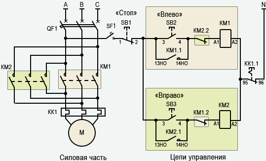
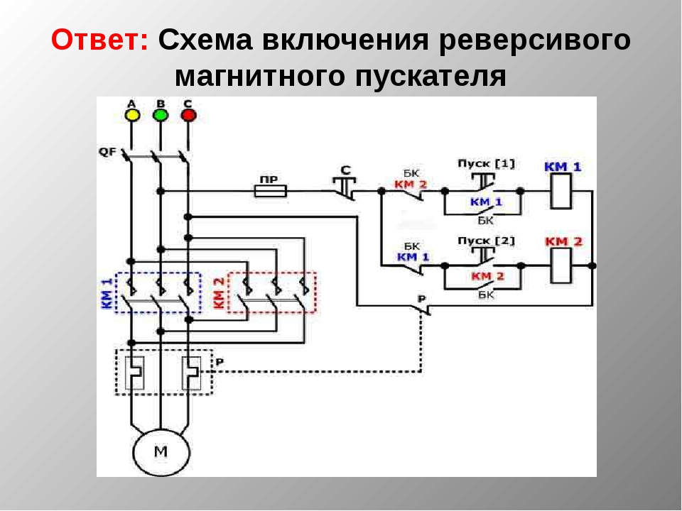
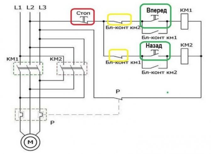
Electrical circuit reversing
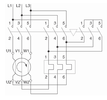
This circuit is assembled from two contactors and a blocking mechanism MB 09.32 or MB 40.95 (depending on the type) designed to prevent simultaneous activation of the contactors.
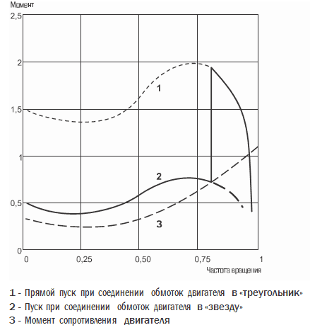
Electric circuit "star - delta"
This starting method is intended for motors whose rated voltage corresponds to the connection of the windings in a "delta". Star-delta start can be used for motors that start without load, or with a reduced load torque (no more than 50% of the rated torque). In this case, the starting current when connected to a "star" will be 1.8–2.6 A of the rated current. Switching from "star" to "delta" should be carried out after the engine reaches the rated speed.


Design and installation features
Connecting clamps provide reliable fixation of conductors:
– for sizes 1 and 2 – with hardened Belleville washers;
– for sizes 3 and 4 – with a clamping bracket that allows the connection of a contact with a larger cross section.
There are two ways to install contactors:
- Quick installation on DIN rail:
KMI from 9 to 32 A (sizes 1 and 2) - 35 mm;
KMI from 40 to 95 A (sizes 3 and 4) - 35 and 75 mm.
- Mounting with screws.
Contactors of the KMI series of the 3rd and 4th dimensions allow mounting on a 75 mm DIN rail.
Contactors of the KMI series of the 3rd and 4th dimensions are equipped with a hole for a grounding bolt.
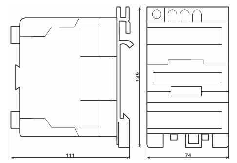
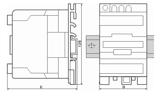
dimensions
| Type execution | Size, mm | ||
| AT | FROM | D | |
| KMI 10910. KMI 10911 | 74 | 79 | 45 |
| KMI 11210, KMI 11211 | 74 | 81 | 45 |
| KMI 11810, KMI 11811 | 74 | 81 | 45 |
| KMI 22510, KMI 22511 | 74 | 93 | 55 |
Dimensions
KMI 23210, KMI 23211
KMI 34010, MI 34011, KMI 35012, KMI 46512
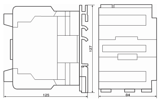
KMI 48012, KMI 49512
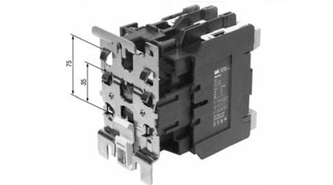
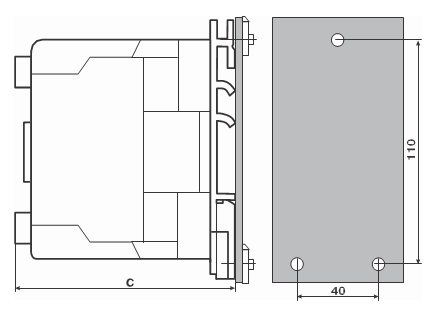
Installation dimensions
Overall and mounting dimensions of KMI contactors when mounted on a 35 mm DIN rail
| Type execution | Size, mm | ||
| FROM | B | D | |
| KMI 10910, KMI 10911 | 82 | 74 | 45 |
| KMI 11210, KMI 11211 | 82 | 74 | 45 |
| KMI 11810, KMI 11811 | 87 | 74 | 45 |
| KMI 22510, KMI 22511 | 95 | 74 | 55 |
| KMI 23210, KMI 23211 | 100 | 83 | 55 |
Model sizeSize, mmCDKMI 34010, KMI 3401113174KMI 3501213174KMI 4651213174KMI 4801214284KMI 4951214284
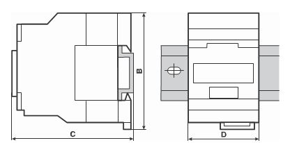
Overall and mounting dimensions of KMI contactors when mounted on a mounting panel or mounting profile
| Type execution | Size, mm | |
| FROM | G | |
| KMI 10910, KMI 10911 | 80 | 35 |
| KMI 11210, KMI 11211 | 80 | 35 |
| KMI 11810, KMI 11811 | 85 | 35 |
| KMI 22510, KMI 22511 | 93 | 93 |
| KMI 23210, KMI 23211 | 98 | 98 |
| Type execution | Size C, mm |
| KMI 34010, KMI 34011 | 114 |
| KMI 35012 | 114 |
| KMI 46512 | 114 |
| KMI 48012 | 125 |
| KMI 49512 | 125 |
Types of electromagnetic starters
To eliminate errors, you need to clarify the names of the products of this group. According to current standards, the starter is a fully functional device with control buttons in a housing protected from dust and moisture. It is allowed to have in the kit:


- thermal relay;
- light indication;
- prefixes with additional contact groups.
The contactor, by definition in the standards, consists of a drive and a contact group. To control such a product, an external push-button post is used. In some models, there is no protective case, since indoor use is implied. Remote connection of the contactor can be automated. Additional external components provide signaling of operating modes and emergencies.
 Control scheme
The figure shows how to connect the contactor to the remote control. This method is used to control remote stationary power units, moving mechanisms (overhead crane drives).Starters for three-phase electric motors are divided into groups to quickly determine the appropriate set of equipment.
Selection of operating parameters
| Group | Permissible motor power (380V), kW | Rated current depending on the version, A | |
|---|---|---|---|
| open | closed | ||
| 1,5 | 3 | 3 | |
| 1 | 4 | 10 | 9 |
| 2 | 10 | 25 | 23 |
| 3 | 17 | 40 | 36 |
| 4 | 30 | 63 | 60 |
| 5 | 55 | 110 | 106 |
| 6 | 75 | 150 | 140 |
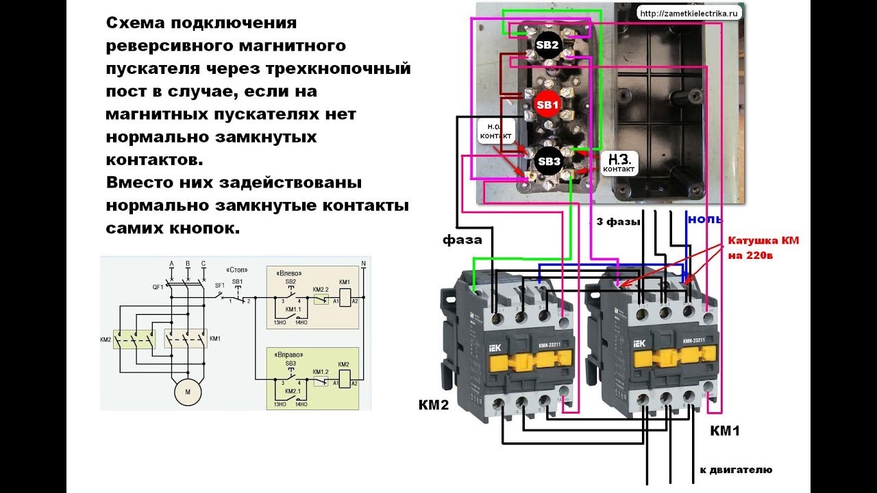
 Reversing starter
The picture shows an example of a model with two Start buttons (indicated by arrows). Such devices are used to control the direction of rotation of the motor rotor. If necessary, one press activates the normal mode or reverse.
Electric starters with thermal relay
These devices prevent damage to the connected equipment in case of violation of the thermal regime. In a typical design, a combined plate of two different metals is used. Passing too much current through this element increases the temperature. Since the materials differ in coefficients of linear expansion, a planned deformation occurs. At a certain level, the control circuit (coil) of the magnetic starter breaks. In some models of the thermal relay, the possibility of adjustment is provided (± 25% of the nominal value). The response time is from 3 to 25 s.
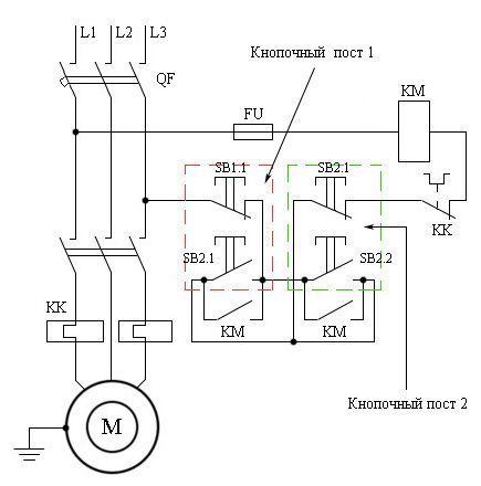
MP connection diagram
A popular scheme for connecting a magnetic starter through a push-button post.
The main circuit has two parts:
Our readers recommend!
To save on electricity bills, our readers recommend the Electricity Saving Box. Monthly payments will be 30-50% less than they were before using the saver. It removes the reactive component from the network, as a result of which the load and, as a result, the current consumption are reduced. Electrical appliances consume less electricity, reducing the cost of its payment.
- Three pairs of power contacts direct electrical power to electrical equipment.
- A graphical representation of the control, which is made up of a coil, buttons and additional contactors that take part in the operation of the coil or do not allow erroneous switching on.
The most common is the single device wiring diagram. She is the easiest to deal with. To connect its main parts, you need to take a three-core cable and a pair of open contactors when the device is turned off.
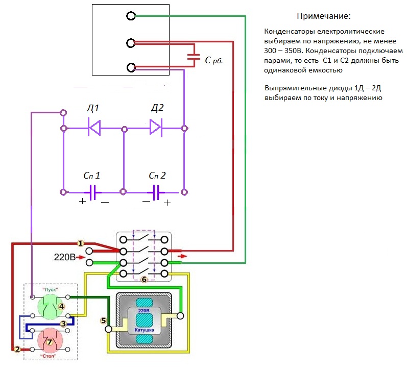
Scheme with connecting a 220 volt coil
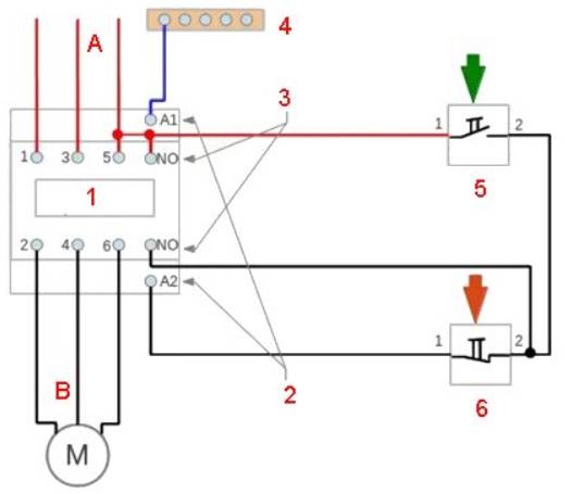
Analyze the design with a voltage of 220 volts. If the voltage is 380 volts, instead of a blue zero, you need to connect a phase of a different kind. In this situation, black or red. In case of blocking the contactor, the fourth pair is taken, which works with 3 power pairs. They are in the upper part, but the side ones are located on the side.
 3 phases A, B and C are supplied to pairs of power contactors from the machine. To turn on when you touch the "Start" button, it is necessary that the voltage is 220 V on the core, which will help the movable contactors connect to those that are stationary. The circuit will begin to close, in order to disconnect it, you need to disconnect the coil.
To assemble the control circuit, you need to connect one phase directly to the core, and connect the second phase with a wire to the start contact.
From the 2nd contactor, we lay 1 more wire through the contacts to another open contact of the Start button. A blue jumper is made from it to the closed contactor of the "Stop" button, zero from the electrical supply is connected to the 2nd contactor.
Working Principle
The principle of operation is simple.If you press the "Start" button, its contacts begin to close and a voltage of 220 volts goes to the core - it starts the main and side contacts and an electromagnetic flux occurs. If the button is released, the contactors of the start button open, but the device is still on, since zero is transmitted to the coil through the closed blocking contacts.
In order to turn off the MP, you need to break the zero by opening the contacts of the Stop button. The device will not turn on again, because the zero will be broken. To turn it on again, you will need to press "Start".
How to connect a thermal relay?

You can also draw up a one-line graphical drawing of connecting a three-phase electric motor to a magnetic starter through a relay.
A relay is connected in series between the MP and an asynchronous electric motor, which is selected depending on the specific type of motor. This device protects the motor from breakdowns and emergency mode (for example, when one of the three phases disappears).
The relay is connected to the output from the MP to the electric motor, electricity passes in it in a sequential manner through the heating of the relay to the electric motor. On top of the relay are auxiliary contactors, which are combined with the coil.
Relay operation
Thermal relay heaters are designed for the maximum value of the current that passes through them. When the current rises to unsafe limits for the motor, the heaters turn off the MP.


Installation of starters inside the electrical panel
MP design allows installation in the middle of the electrical panel. But there are rules that apply to all devices. To ensure high reliability of operation, it is necessary that the installation is carried out on an almost straight and solid plane.Moreover, it is located vertically on the wall of the electrical panel. If there is a thermal relay in the design, then it is necessary that the temperature difference between the MP and the electric motor be as small as possible.


