- Wiring diagrams
- What are timers, pause relays, delays
- Where apply
- Device, varieties, features
- Varieties and characteristics of impulse relays
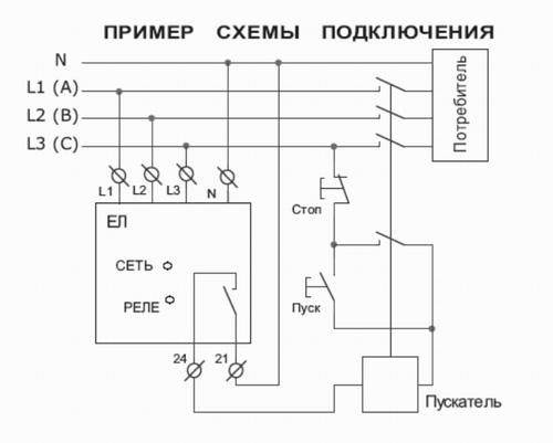
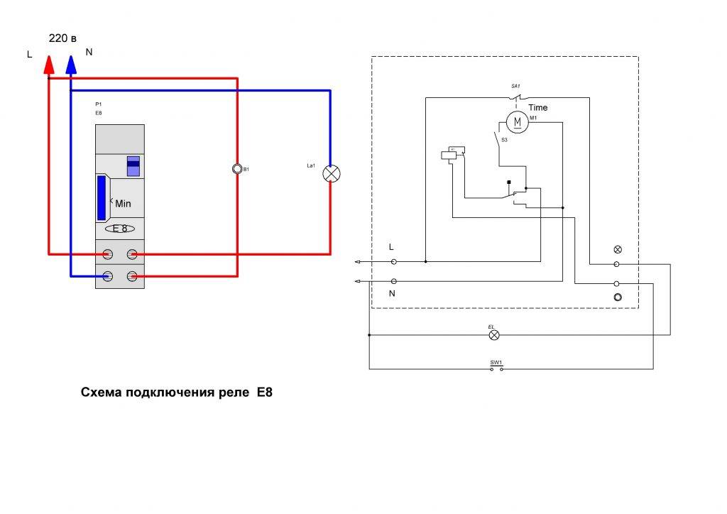
- Wiring diagram
- Without automation
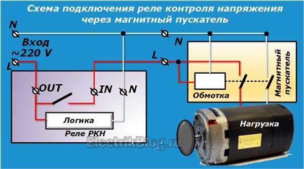
- Via pressure switch
- With control box
- Electromagnetic starter
- Mounting Features
- Connecting the water pressure switch
- Electrical part
- Pipe connection
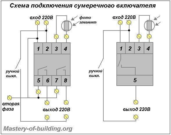
Wiring diagrams
The impulse relay can be used to control the light. To ensure the operability of electrical systems with installed switching elements of this type, it is necessary to correctly perform work on connecting conductors.
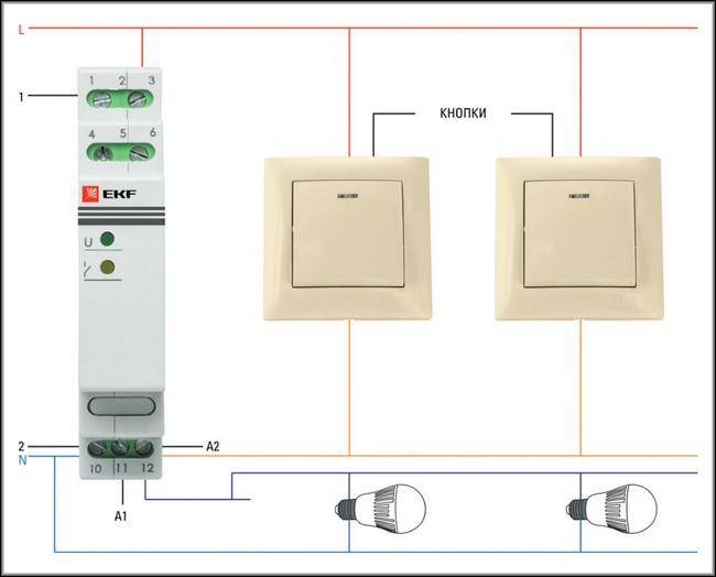
First of all, it should be borne in mind that the pulse-type relay is not equipped with any protection elements, therefore, if a short circuit occurs in the electrical wiring of the lighting devices, not only the relay contacts may burn, but also the ignition of any flammable objects located in close proximity to copper conductor. To minimize the possible consequences, the installation of impulse relays should be carried out only after the machine (or fuses (plugs)).
Pushbutton switches are used to switch relay modes.Such elements of electrical fittings are equipped with spring elements that return the button to its original position immediately after the cessation of mechanical pressure on its surface. This is a very important point, because if the contact is closed for too long, the coil winding may overheat and the product (electromechanical) will fail.
Many manufacturers of impulse switches indicate in the product documentation that it is impossible to supply electric current to the coil for a long time (usually no more than 1 s).
The number of switches with which a signal is sent to the impulse relay is not limited in any way, but, in many cases, there are 3-4 buttons in the device connection diagram. This is enough to control the light from several places.
All pushbutton switches are connected in parallel to each other. This feature of the control of the impulse device allows the use of a significantly smaller number of wires, in comparison with other methods of mounting a control system for one lighting fixture from different locations. One wire of the contact system of the switches is connected to the wiring phase, the other is connected to the impulse relay (contact A1).
In addition to connecting the phase wire from the switches, the phase is connected to contact "2" of the pulse device. Thus, the transmission of a signal about switching on (off), as well as providing the device with electric current for supplying voltage to consumers (lighting devices) is ensured.
"Zero" is connected to pin "2". Lighting devices are connected to the "ground" not through a switching device. The neutral wire is connected to the lighting device from the zero bus.
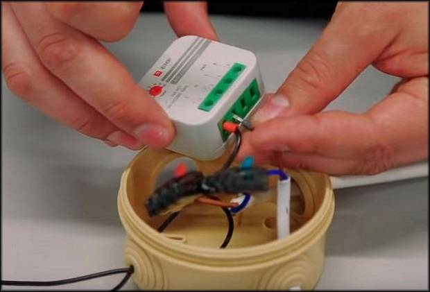
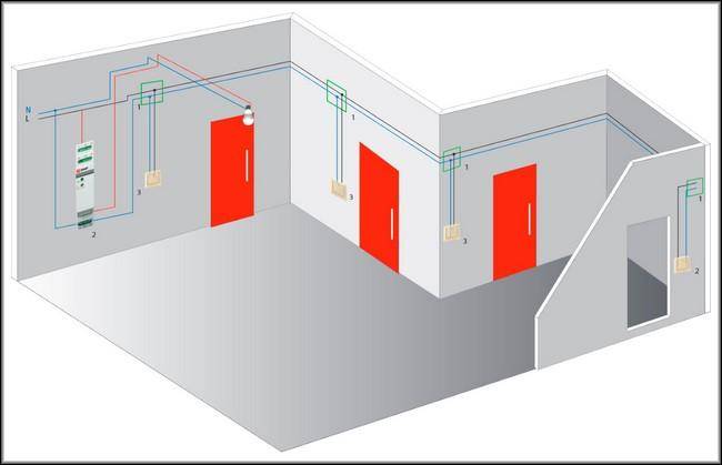
The physical placement of the impulse relay is possible both in electrical panels and in close proximity to the lighting device (installation is carried out in a junction box).
What are timers, pause relays, delays
Let's make a reservation right away: home-made auto-timers adjust the delay from a few seconds to 10-15 minutes. There are schemes only for incl. and for on/off load, as well as for activation at certain times of the day. But their delay range and options are limited, there is no function of periodic self-operation several times and adjustment of the intervals between such cycles, like factory outlet devices. However, the possibilities of home-made products (there are also ready-made similar simple modules for sale) will be enough to activate the ventilation of the garage, lighting in the pantry and similar not too demanding operations.


A time relay (timer, pause, delay relay) is an automatic release that operates at the moment set on it by the user, turning on / off (closing / opening contacts) an electrical appliance. The timer is extremely practical in situations where the user needs the device to be activated or deactivated when they are in a different location. Also, such a node will help out in ordinary household cases, for example, it will insure when they forget to turn off / on the equipment.
Thus, the time relay will exclude situations when the appliance was left on, forgot to turn it off, respectively, it burned out or even worse, caused a fire. By turning on the timer, you can go about your business without worrying that you will have to return at a certain time to service the equipment.The system is automated, the unit will turn itself off when the set period on the release expires.
Where apply
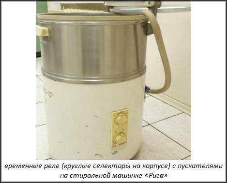
Many are familiar with clicks in Soviet washing machines, when a certain delay was set to on / off with large graduated selectors. This is a vivid example of this device: for example, they set the work for 10-15 minutes, the drum was spinning for this time, then, when the clock inside reached zero, the washing machine turned itself off.
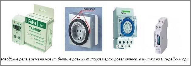
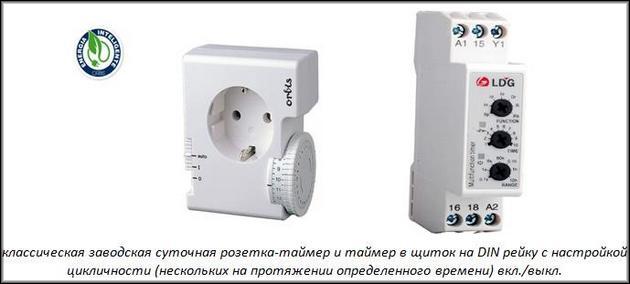
Time relays are always installed by manufacturers in microwave ovens, electric ovens, electric water heaters, automatic watering. At the same time, many devices do not have it, for example, lighting, ventilation (exhaust), then you can buy a timer. In its simplest form, it looks like a small rectangular block with time selectors and a plug for a regular outlet (“daily” timer sockets) into which it is inserted. Then the plug of the power cable of the serviced device is inserted into it, the delay time is adjusted by the controls on the case. There are also standard sizes for placement by connecting to the line (with wires, wiring, for switchboards), for integration into devices.
Device, varieties, features
Mostly, timers in factory electrical devices with releases are based on a microcontroller, which often also controls all modes of operation of the automated apparatus where they are installed. The described combination of functions is cheaper for the manufacturer, since it is not necessary to manufacture separate microcircuits.
We will describe the simplest time relay circuits with a delay, only with the on / off option. and selection of a temporary pause in a small range (up to 15–20 minutes):
- for low-voltage power supply (5–14 V) - on transistors;
- on diodes - for power supply directly from the mains 220 volts;
- on microcircuits (NE555, TL431).
There are special factory modules, they can be bought on Internet sites (Aliexpress, similar and specialized resources), on radio markets, in special stores. Completely handicraft products are created according to similar schemes, mainly for simple tasks: elementary disconnection / coupling of contacts at a certain, set point in time, while the delay range is small from seconds to 15-20 minutes.
Varieties and characteristics of impulse relays
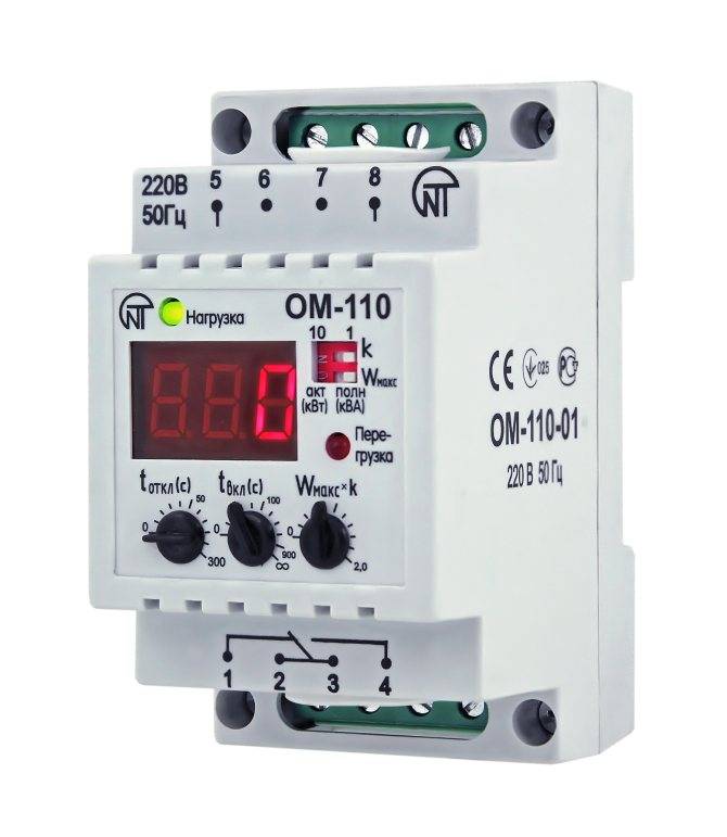
Pulse relays can have a modular design, for mounting on a DIN rail in a shield, but devices of various sizes and shapes are also available with a different mounting method. Modular devices manufactured by different manufacturers may also differ in appearance. For example, pulse relays from ABB, Schneider Electric, have operation indicators and a manual mechanism control lever.
It will be interesting Description and principle of operation of solenoids
The designation of the connection terminals may also vary. In the course of development, products of the same brand also change. For example, the relay of the previously popular E251 series from ABB, already discontinued, looks like this, and its analogue E290 now has a slightly different look. The series from the same manufacturer also differ in the internal circuitry. The main characteristics of impulse relays are:
- Number and initial state of contacts;
- Rated control voltage;
- Coil operation current;
- Rated current of the power circuit;
- Control pulse duration;
- Number of connected switches;
The last specified characteristic depends on the presence of backlights in the switches, the total current of which can lead to the operation of the coil. If a impulse relay electronic, then it is subject to radio interference and interference from surrounding power circuits. Since there is a wide variety of bistable relays, without reference to a specific manufacturer, only a generalized connection diagram can be considered.
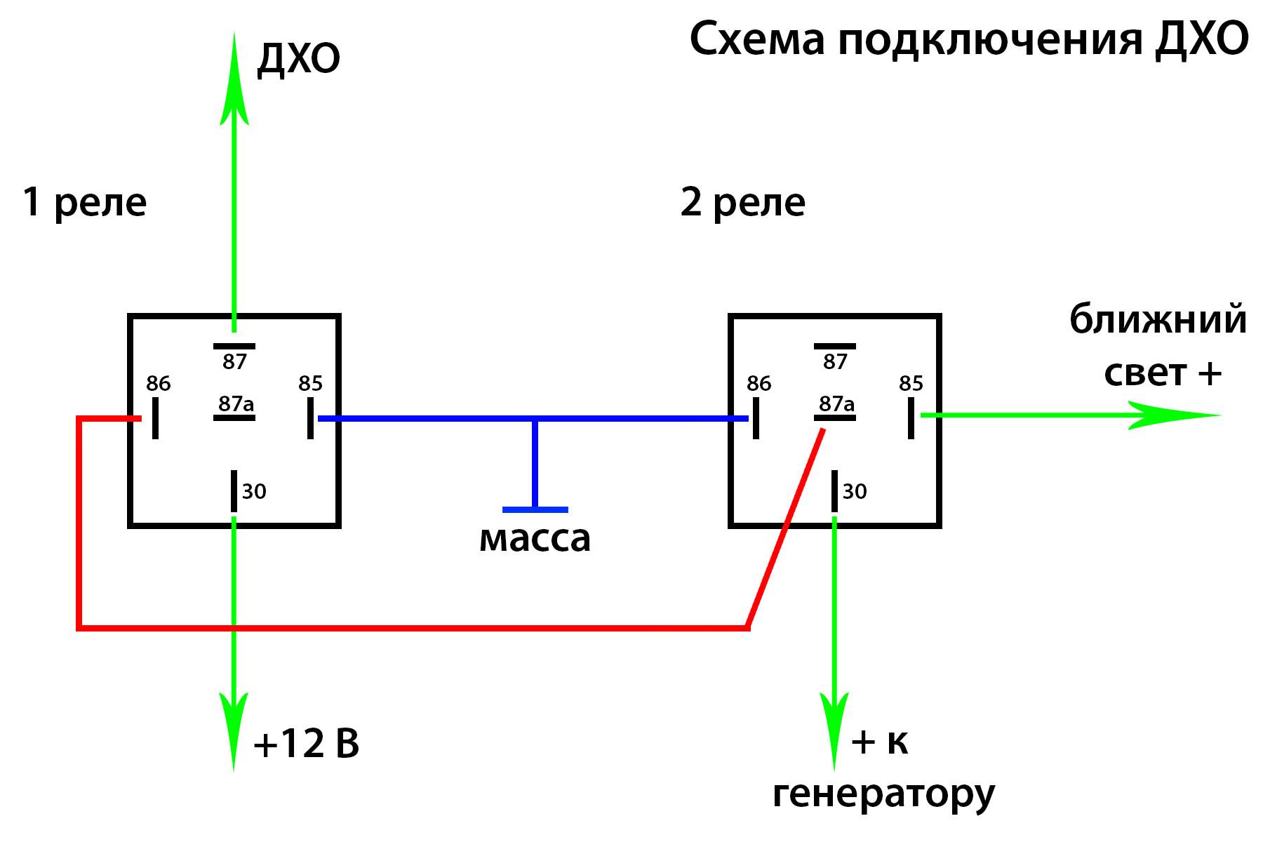
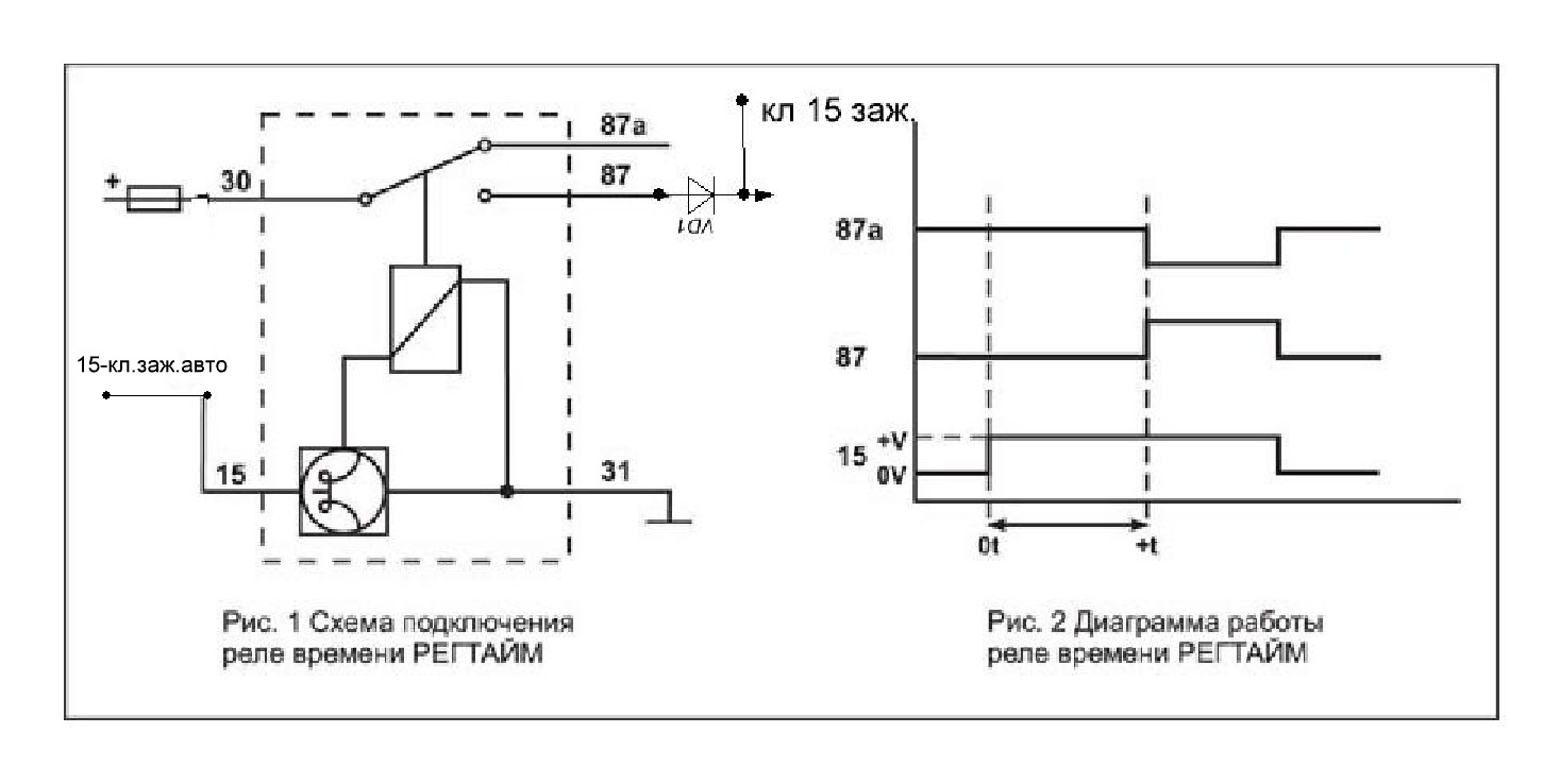
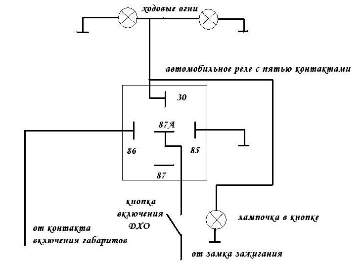
Relay actuation scheme
The common feature of these relays is that they do not have built-in overload protection and must be protected by circuit breakers.
Since a small current is required to operate the coil compared to the switched load, the control circuits can be carried out using cables with a conductor cross section of 0.5 mm², but in this case a separate circuit breaker must be installed for this wiring, to prevent the wires from igniting when they are short circuit.
As a rule, manufacturers indicate the time during which the coil can be energized. For example, at ABB it is not limited, but for less famous brands, impulse relays can heat up when there is an electric current in the coil circuit for a long time, therefore, when buying an impulse relay, you need to specify this parameter, because there may be cases when accidentally moved furniture will cause a permanent pressing the switch button.


If you look into the ABB catalog, you can see that there are impulse relays (old series - E256, new analogue E290-16-11 /), having one normally open and one normally closed contact, actually operating in switch mode.Such devices can be used to control lighting systems in production, to switch between main and emergency lighting. Thanks to this function, the production room will never be in the dark due to the fault of the personnel who forgot to turn on the emergency light - switching is carried out with one press of the switch button.
Impulse relay with digital control
It is also possible to control the lighting both locally (one impulse relay is controlled using several buttons connected in parallel) and centrally (simultaneously for several identical devices) using two keys - on and off. For example, the connection diagram of the E257 series relay. Here, by pressing the central buttons (ON, OFF), all relays are controlled, plus each has its own local control. The updated line of ABB uses the principle of combining modules to create multi-level control systems.
The use of different control voltages also expands the functionality of lighting control devices. For example, the impulse relay of the E251-24 series (its updated analogue E290-16-10/24) is controlled by a constant voltage of 12V (or alternating 24V), which makes it safe to operate switches located in wet environments where there is a risk of electric shock.
It will be interesting What is a thermal relay
Such a device can be successfully used to control lighting in a bath or sauna, where the use of devices operating with mains voltage is not allowed.In addition, a low-voltage control signal can be generated by various computerized devices, which makes it possible to automate lighting control processes.
Wiring diagram
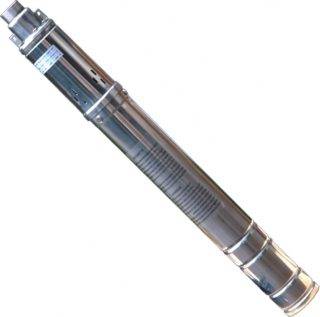
Depending on the needs of the user and his financial capabilities, you can choose one of the methods for connecting the deep pump to the electrical network.
Without automation
Without auxiliary control devices, the pump is connected using a pre-installed electrical outlet with a ground contact. The pump is also grounded. For this, the main bus of the house is used, which is connected to the existing ground loop of the building.
A three-core cable is used to supply electricity to the outlet. The power supply voltage of the submersible pump is 220V. Do not use 380 or 150 volt outlets.
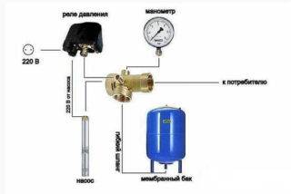
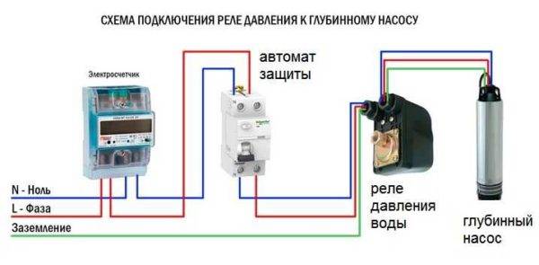
Via pressure switch
To reduce the cost of a set of pressure equipment, you can apply a connection scheme for a borehole pump only with a pressure switch without a control unit. The device turns off the pump when the pressure reaches its maximum, and starts it when the indicators decrease to a minimum.
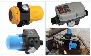
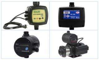
With control box
When choosing an automation model, you first need to find out which protective system has already been supplied by the manufacturer in the pump. Modern devices are already protected from overheating and idling. Sometimes the equipment is equipped with a float mechanism. Given these data, you can choose one of three options for automation - simple, with a second or third generation electric control unit.
The simplest protection is most often used for automatic water supply. The control unit here is assembled from three devices:
- Dry run blocker.It will turn off the machine, which works without water, preventing overheating. Sometimes an additional installation of a float switch is allowed. It performs the same functions, turns off pumping equipment when the water level drops, preventing it from overheating. It may seem that the devices are primitive, but they provide effective protection for the electric motor.
- Hydraulic accumulator. Without it, it will not work to provide automatic water supply. The hydraulic tank works as a water storage tank. Inside is a working mechanism - a diaphragm.
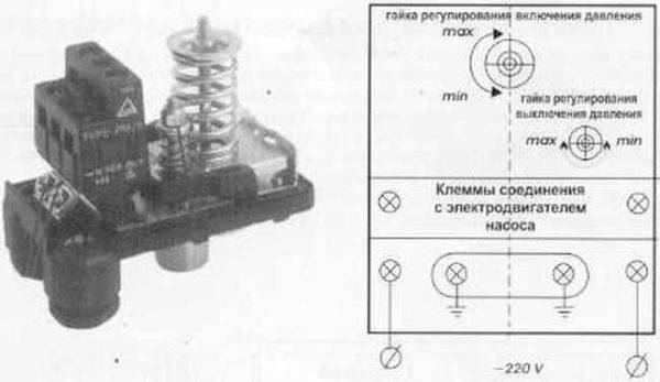
- Pressure switch complete with pressure gauge. This device allows you to configure the operation of relay contacts.
It is not difficult to equip pressure equipment with your own hands with simple automation. The principle of operation of the system is simple: when water is consumed, the pressure in the hydraulic tank decreases. When the minimum indicator is reached, the relay starts the pressure equipment, which pumps water into the storage tank. When the pressure in the hydraulic accumulator reaches its maximum, the relay device switches off the unit. In the process of water consumption, the cycle is repeated.


Adjustment of the pressure limits in the accumulator is carried out by means of a relay. In the device, using a pressure gauge, set the minimum and maximum response parameters.
In second-generation automation, the connection goes through an electrical unit with a set of sensors. They are mounted directly on the pressure equipment, as well as inside the water supply network, and allow the system to function without a hydraulic tank. The impulse from the sensors is fed to the electronic unit, which controls the system.
The operation of pressure equipment with such a scheme for connecting a submersible well pump to automation:
- The liquid accumulates only in the water supply, where one of the sensors is placed.
- When the pressure drops, the sensor sends an impulse to the control unit, which starts the pump.
- After reaching the desired pressure of the water flow in the water supply, the pump is turned off in a similar way.
To install such automation, you will need basic knowledge in electrical engineering. This and the previous protection work almost the same - according to water pressure. However, the electric unit with sensors is more expensive, which is why it is not so popular among consumers. Even when using automation, you can not use a hydraulic tank, although in case of power outages you will not be left without water with it. There is always a reserve in the drive.
Automation of the third generation is reliable, high-quality and expensive. Its installation allows you to significantly save on electricity due to the ultra-precise adjustment of the operation of the electric motor. The scheme for connecting advanced automation to a deep well pump is very complicated, so you should contact a professional to connect it. But it provides complete protection of the motor from various breakdowns, for example, overheating during dry running or burning of the windings during power surges in the network.
The unit operates from sensors without a hydraulic tank. Efficiency is achieved through fine adjustments.
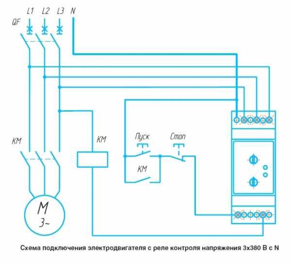
Electromagnetic starter
An electromagnetic starter is an electrical device that allows you to start, stop and protect three-phase asynchronous electric motors.
In addition, these devices allow you to start and turn off any kind of load, for example, heating elements, lighting sources, and others.

Electromagnetic starters are produced in single or double versions. The latter have mechanical protection against simultaneous launch.
Open devices are used in panel installations, they are used inside closed specialized cabinets, as well as in other places that are reliably protected from small particles and mechanical damage.
In contrast, protected starters can be used indoors if the environment is not very dusty. There are also starters that have reliable protection against moisture and dust, they can be used both in indoor and outdoor installations.
Mounting Features
In order for the starter and time relay to work reliably, they must be installed correctly. Devices must be rigidly fixed.


Do not install devices in places that may be subject to shock and vibration, for example, where electromagnetic devices (more than 150 A) are installed that create shock and vibration during switching on.
If one conductor is connected to the contacts of the magnetic starter, it must be bent in a U-shape to prevent the clamp spring washer from being skewed.
If two conductors are connected, they must be straight and each must be on the same side of the clamp screw. Be sure to check the reliability of fixing the conductors.
Before connecting to the starter, the ends of the copper conductors must be tinned, and the stranded conductors must be twisted. However, the contacts and moving parts of the starter must not be lubricated.
Connecting the water pressure switch
The water pressure switch for the pump is connected immediately to two systems: to electricity and plumbing. It is installed permanently, since there is no need to move the device.
Electrical part
To connect a pressure switch, a dedicated line is not necessary, but desirable - there are more chances that the device will work longer. A cable with a solid copper core with a cross section of at least 2.5 square meters should go from the shield. mm. It is desirable to install a bunch of automatic + RCD or difavtomat. The parameters are selected according to the current and depend more on the characteristics of the pump, since the water pressure switch consumes very little current. The circuit must have grounding - the combination of water and electricity creates a zone of increased danger.
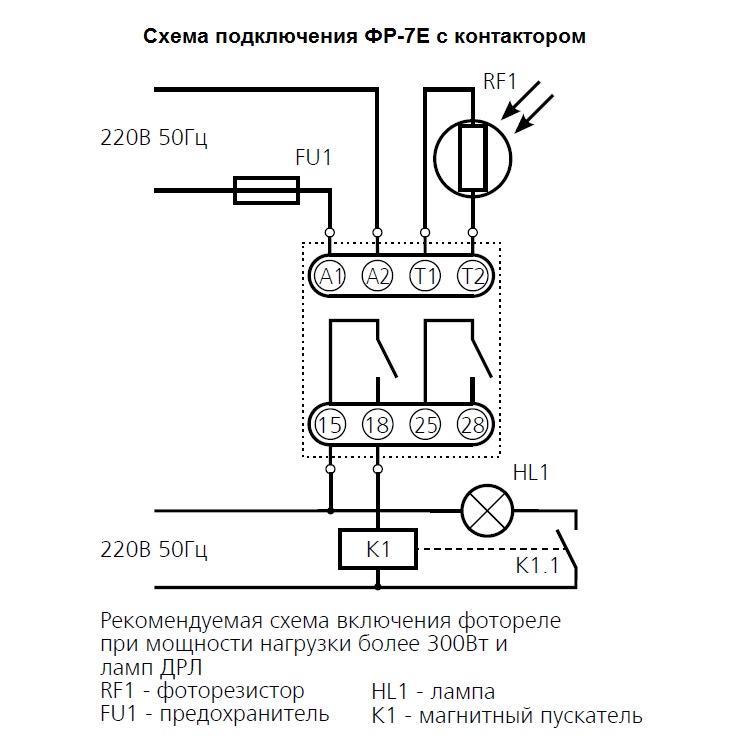
Scheme of connecting the water pressure switch to the electrical panel
Cables are brought into special inputs on the back side of the case. There is a terminal block under the cover. It has three pairs of contacts:
- grounding - the corresponding conductors coming from the shield and from the pump are connected;
- terminals line or "line" - for connecting the phase and neutral wires from the shield;
- terminals for similar wires from the pump (usually on the block located above).
The location of the terminals on the housing of the water pressure switch
The connection is standard - the conductors are stripped of insulation, inserted into the connector, tightened with a clamping bolt. Pulling on the conductor, check whether it is securely clamped. After 30-60 minutes, the bolts can be tightened, since copper is a soft material and the contact may loosen.
Pipe connection
There are different ways to connect a water pressure switch to a plumbing system. The most convenient option is to install a special adapter with all the required outlets - a five-pin fitting. The same system can be assembled from other fittings, just a ready-made version is always better to use.
It is screwed onto a pipe on the back of the case, a hydraulic accumulator is connected to the other outlets, a supply hose from the pump and a line that goes into the house. You can also install a mud sump and a pressure gauge.
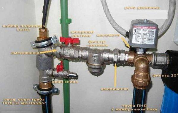
Example of tying a pressure switch for a pump
A pressure gauge is a necessary thing - to control the pressure in the system, to monitor the settings of the relay. Mud collector is also a necessary device, but it can be installed separately on the pipeline from the pump. There is generally desirable a whole system of filters for water purification.


With this scheme, at a high flow rate, water is supplied directly to the system - bypassing the accumulator. It begins to fill up after all the taps in the house are closed.


