- Connecting a walk-through switch
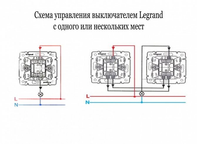
- What does a walk-through switch with 2 or more places look like?
- Wiring diagram for two switches.
- Some subtleties
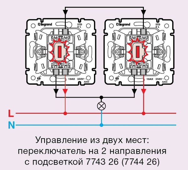
- Lighting control circuit from two places
- Application examples
- Cross disconnect principle
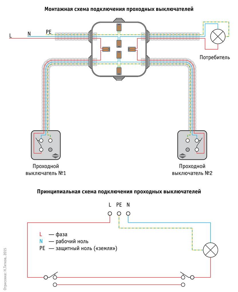
- Schemes for installing walk-through switches
- Wiring diagram for a single-gang lighting switch
- Scheme of installation of 2-way switch
- Junction box assembly
- Connection diagrams for various types of pass-through switches
- Post navigation
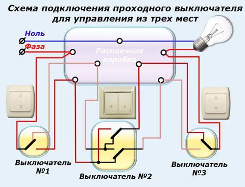
- How to connect a walk-through switch - a 3-place luminaire control circuit
- How to choose the "right" place for the switch
Connecting a walk-through switch
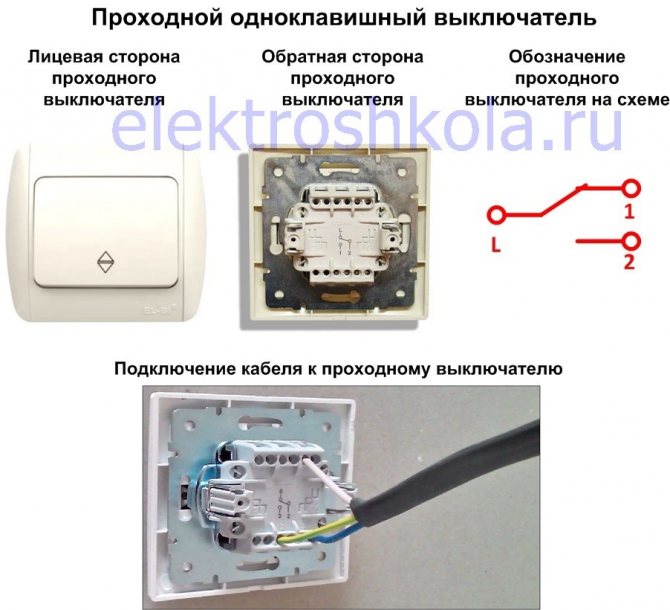
What does a walk-through switch with 2 or more places look like?

The above circuit will allow you to fully control the lighting system, however, the above circuit does not protect a person from electric shock. Hence the name - pass-through or mid-flight switch.
It is very easy to assemble such a scheme. For this, a crown for concrete d mm is suitable. The advantage of this method is high reliability, since the 2 conductors are fused under the influence of a large current, providing a low connection resistance. Figure 5
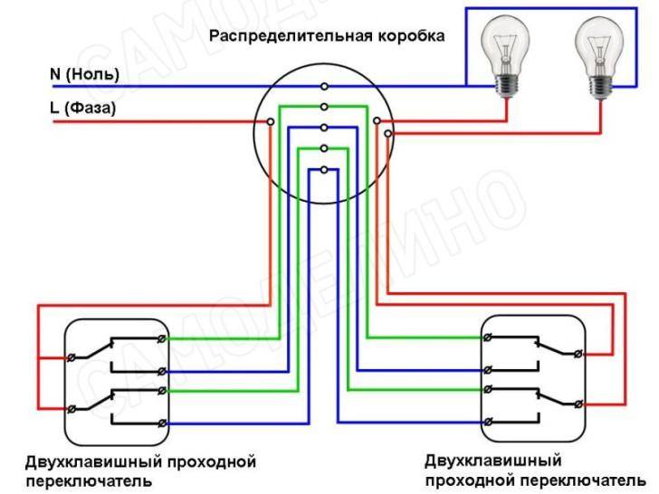
Figure 8. Connecting a double-gang switch is made in accordance with the circuit diagram shown in Figure 5. Conclusion In the article, we examined all frequently asked questions on the topic of connecting switches. By analogy, you can increase the number of control places to any value. We stretch a three-wire wire to each pass-through switch, and a four-wire wire to each cross switch.
How to connect a pass switch
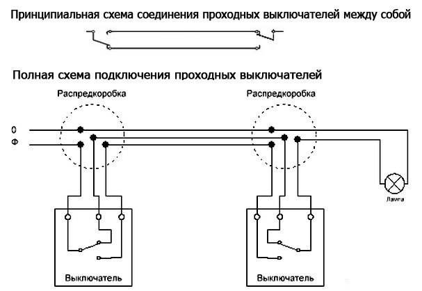
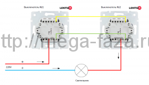
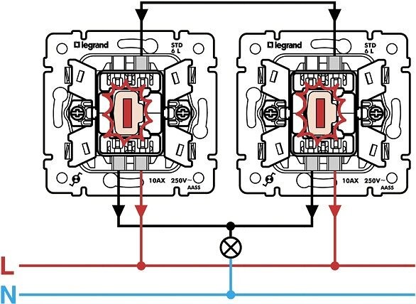
Wiring diagram for two switches.
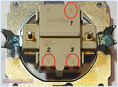
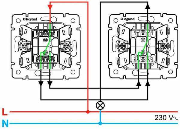
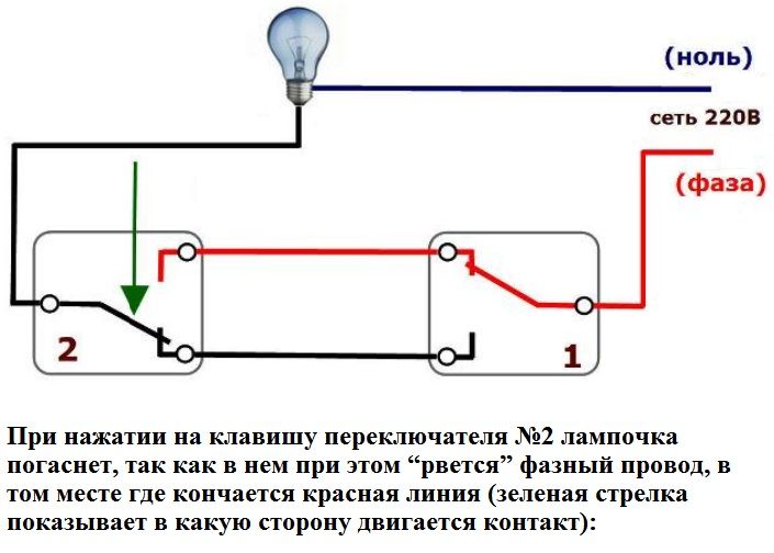
On the case of some models of pass-through switches, conclusions are indicated so that the contacts do not ring during the installation process. In the model considered in the article, the conclusions are indicated by arrows:
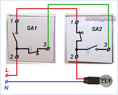
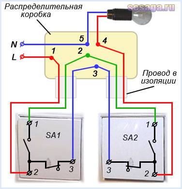
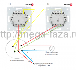
And now consider the connection diagram of two switches SA1 and SA2.
Phase L connected to terminal 2 switch SA1, and to the terminal 2 switch SA2 upper lamp terminal connected EL1. Switch terminals of the same name 1-1 and 3-3 interconnected by red and green jumpers. Zero N connected to the bottom terminal of the lamp.
Let's analyze how the circuit works.
In the initial state of the switches, the lamp does not light. Phase L goes through contact 2-3 switch SA1 and through the green jumper enters the terminal 3 switch SA2 and goes nowhere further, since the contact 2-3 open.
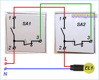
When pressing the switch SA2 his contacts 1-2 and 2-3 switch and contact 1-2 opens up, and 2-3 closes. Then the phase L through closed contact 2-3 switch SA1 and a green jumper passes a closed contact 2-3 switch SA2 and from the terminal 2 goes to the lamp. The lamp is on.
Now press the switch SA1 and his contacts 1-2 and 2-3 switch and the lamp goes out. Here the phase L through closed contact 1-2 switch SA1 and a red jumper falls on the terminal 1 contact1-2 switch SA2 and does not go further, since the contact 1-2 open.
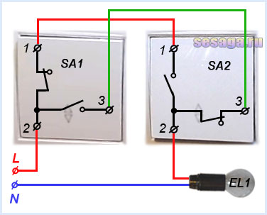
Now if you press the switch SA2, the lamp will turn on again. Phase L through closed contact 1-2 switch SA1, a red jumper and a closed contact 1-2 switch SA2 hits the lamp.


And regardless of which of the switches the lamp is turned on or off, it can always be turned on or off by any switch. This is how toggle switches work.
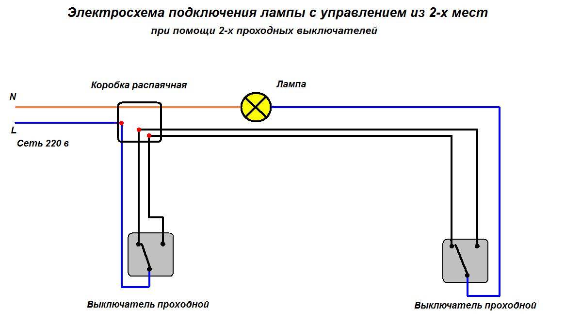
We still have to consider the wiring diagram using a junction box.
Phase L enters the junction box and at the point (1) is connected to the core wire coming from the terminal 2 switch SA1. Terminals of the same name 1-1 and 3-3 switches are interconnected at points (2 and 3). From terminal 2 switch SA2 the core of the wire goes into the box and at the point (4) is connected to the core wire coming from the lamp output. The second output of the lamp is connected to zero N at point (5).
And now the most basic thing that you should remember when installing walk-through switches: if after assembling the circuit, the lighting does not work as it should, as required, means, switch terminal 2 incorrectly connected. Check if this terminal is connected correctly.
And in addition to what has been said, I suggest watching the video and finally understanding this topic.
That's all I wanted to say about the device and the connection of the pass-through switches.And in the next article, you will learn how to connect a cross switch, which makes it possible to control lighting from three or more places.
Good luck!
Some subtleties
If it is required to create several intermediate control points for lighting fixtures, for example, for flights of stairs of the entrance of a five-story building, then all of them are switched on sequentially to each other. The same phase must pass through them - this is a prerequisite.
There is an opinion that for the installation of intermediate on-off points for lighting fixtures, it is worth using only a four-core cable. This simplifies installation work.
There is some truth in this, but there is a real threat to include wire of improper section in the line. This is because cables with so many conductors are designed for three-phase current, the fourth core in them is one third smaller in diameter, it is connected to the ground loop. Phase current cannot be passed through it.
All work on connecting an additional on-off point is carried out with the voltage removed and in compliance with other electrical safety measures.
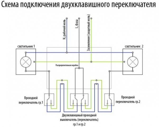
Wiring diagram for through and cross switches from 3 places:
Lighting control circuit from two places
In this case, the easiest and most reliable way to turn off the light switch in the dashboard. Since there will be four connected wires in the junction box.
For example, the maximum allowable distance from the switch to the switch must be at least 30 m. They have six contacts.Installation of a junction box for one lighting group Be sure to turn off the power before installing the switch.
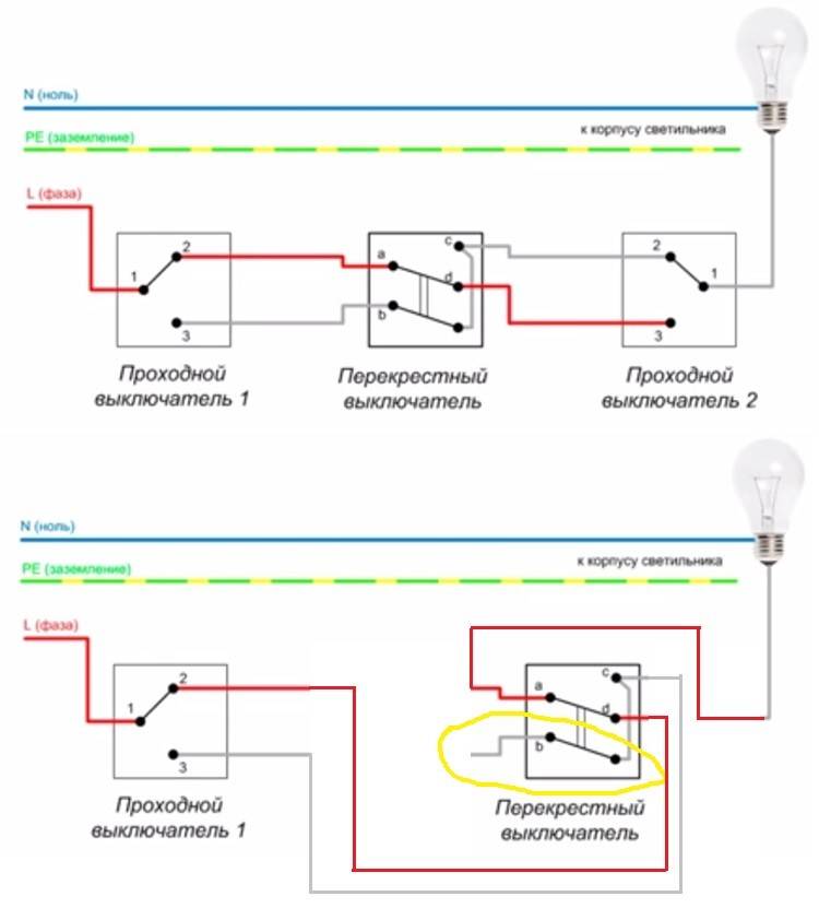
A phase line is connected to the common terminal of any of the two-key switches. The two output contacts of the pass switch are connected to the two input contacts of the cross switch.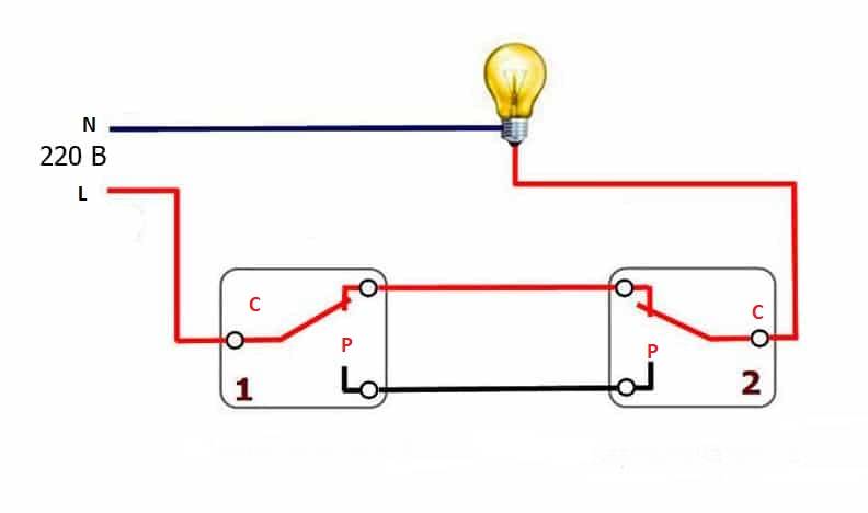
They are often absent on Chinese copies. Then, when the key is released, it is clamped. First, you need to know in detail how to connect a pass-through switch, existing control circuits and installation methods.
3 pairs of wires are connected to the output, which lead to the second pass-through switch and are connected in pairs to the input terminals of the device. If you want to control the operation of two lamps from three or four points, you will have to purchase two cross switches.


Application examples
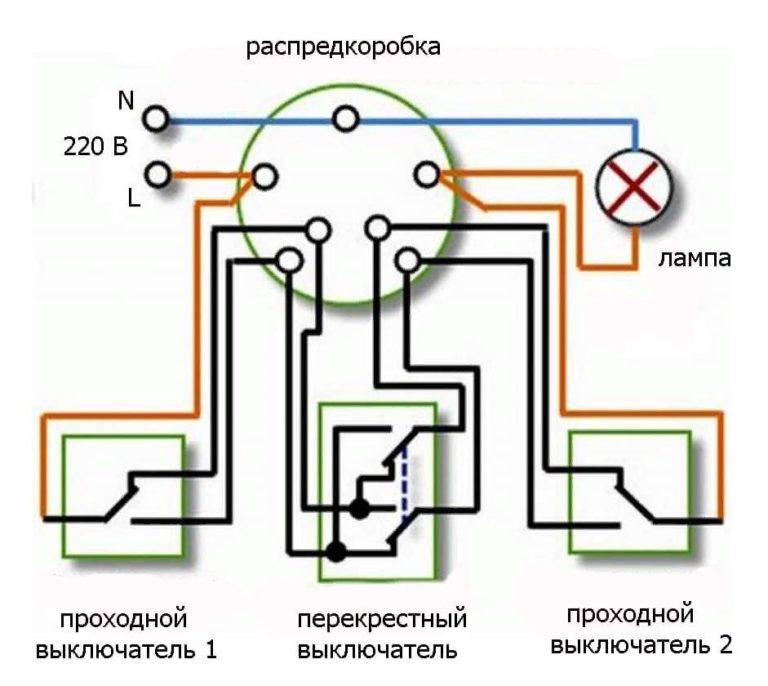
A widespread version of the three-point scheme: N - electrical zero; L is the electrical phase; PV1 - the first two-key switch; PV2 - the second two-key switch; PV3 - cross switch A kind of connection instruction in this case looks something like this: A wiring and connection diagram is created. The ability to turn on and off 2 different lights from four points can come in handy in a long hallway of a house with a lot of rooms. AT this particular example there are two more possibilities: when working in the yard, you can turn on the lighting; if you are waiting for guests, you can control the light on the street while at home.
Another option takes into account the requirement cable laying using junction boxes, which can be done in a new building or when replacing wiring.The round pieces inside the box are soldered wires, made in the form of twists with welding, crimped with self-clamping insulating caps, connected by terminals or a screw connection. Firstly, only a single pass-through switch is most often in demand. If we press the key of the first switch and move it to the raised position, then the changeover contact of this switch will also change its position accordingly and close the electrical circuit.
Is it necessary to ground lighting circuits in which a walk-through switch is installed? When carrying out work, it is necessary to observe safety regulations.
Scheme of connection of the pass-through switch - switch.
Cross disconnect principle
The cross switch is similar to a regular one-key switch, the only difference is that there are four terminals inside. Cross is named because of the two electrical lines that it switches, they are connected in a cross.
The cross disconnector disconnects the first and second circuit breaker at the same time, then connects them synchronously. From this movement of the contacts, the light turns on and goes out.
Advice! Pay special attention to the correct connection of the ends of the electrical cables, otherwise the whole system will not work. The number of points can be different, but the more there are, the more difficult the switching in the junction box. It is necessary to clearly mark the wires when conducting, so as not to confuse
It is necessary to clearly mark the wires when conducting, so as not to confuse
The number of points can be different, but the more there are, the more difficult the switching in the junction box. It is necessary to clearly mark the wires when conducting, so as not to confuse.
Schemes for installing walk-through switches
On the topic of pass-through switches, a lot of questions come to the mail about the connection diagrams of both single-gang and, in particular, two-gang switches.
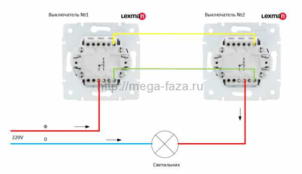
The basis of the questions is how many wires are needed for the correct operation of the pass-through switch. For the operation of single-key feedthroughs, three cable cores are connected to each switch.


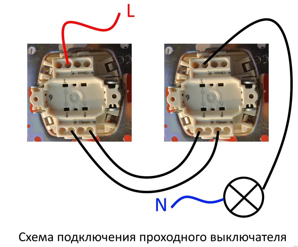
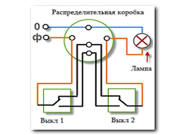
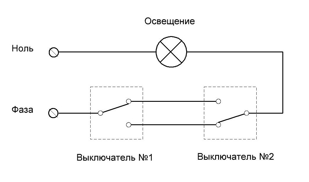
Wiring diagram for a single-gang lighting switch
As we can see from the diagram, zero goes to the light bulb by direct supply from the voltage source, and the phase is fed to the common contact of one of the switches (B1). Further, the changeover contacts are interconnected and the phase exits the load from the common contact of the second switch (B2). Observing the color scheme of the conductors, and it can be different, it is difficult to confuse anything here.
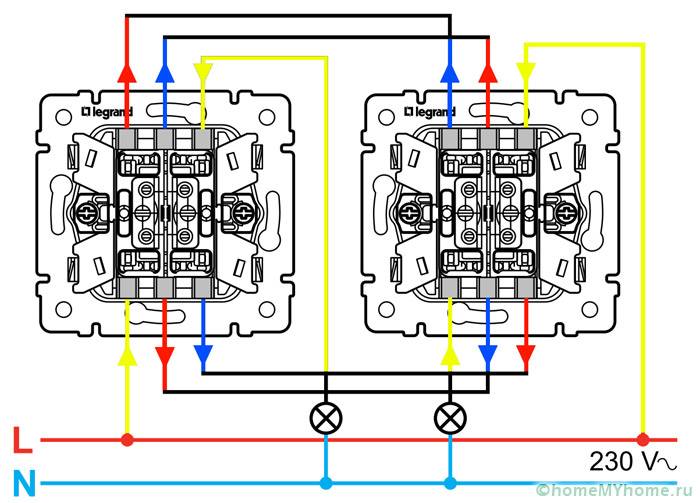
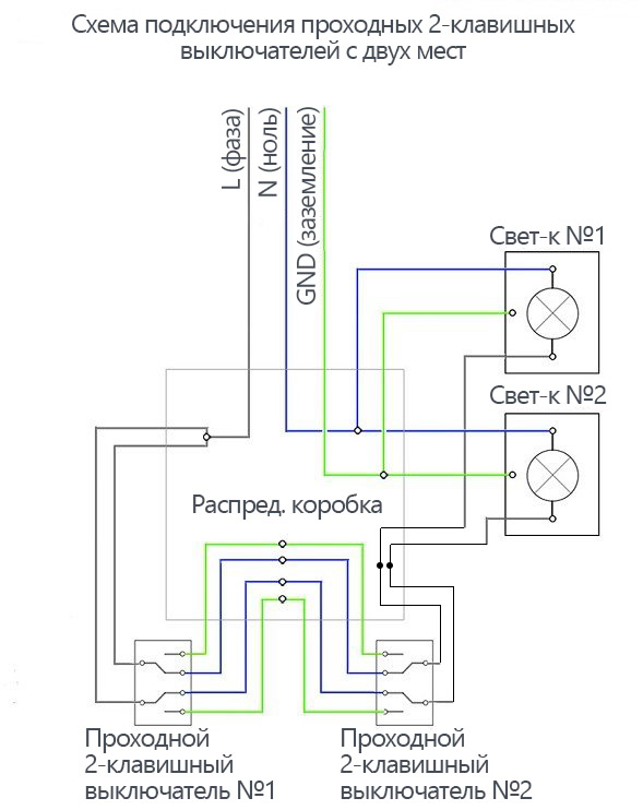
Scheme of installation of 2-way switch
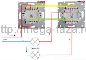
The two-gang passage switch according to the principle of operation does not differ from the one-gang. It is simply designed for pass-through switching on / off of two groups of lighting. Accordingly, two three-core cables come from the junction box to each socket of the two-gang switch. In this connection scheme, in one of the groups (where the voltage source will be), you can use a 5-core cable by applying voltage to the main contact of the second group with a jumper from the first.
Topic of questions and answers on walk-through switches
There are also questions about the problem of turning off the machine in the switchboard when pressing any key of the pass-through switch. Here is the answer. If the feed-through circuit worked properly before, and the reason appeared “suddenly”, you need to look first of all in the load (lamps, cartridges, lamps, etc.).If the bushing does not start normal operation immediately after installation, check the connection diagram in the mounting box. Perhaps a neutral conductor was connected to one of the sides in the circuit.
A common question from users is whether it is possible to implement a pass-through scheme along the old lighting lines without wiring? In 98% - no. To do this, you need a connecting desoldering between the points. I had the only case in practice when the client, without destructive electrical work, managed to switch off two single-gang switches in the apartment. But the prevailing conditions helped here. First, a conventional two-gang switch was installed at the front door, working on the main ceiling lighting, and the second group turned on a small sconce near the corridor mirror. That is, we had three cable cores. The second condition - at the end of a long corridor near the bathroom in the block with light switches, the hood switch was inactive (during installation, at the request of the owners, the builders connected it directly from the lighting), so here we also had a free pair. And the third most important condition - the electrician who carried out electrical work during the repair period brought all the ends of the cables into one junction box. There is not even a box, but an internal mounting box measuring 200x300 mm. Then there was no thought to photograph that "web" that was inside the box, but it looked depressing. A couple of hours to find the right lines, rewiring, installing two single-gang toggle switches. By the way, I took the incoming voltage from the side of the double wire by applying a voltage from the bathroom lighting phase with a jumper.At the same time, the main ceiling lighting was powered from the walk-through switches, and the sconces were replaced with a wall-mounted LED lamp with a motion sensor.
If someone has any questions about the pass-through switches, write to the mail (administrator) in the footer of the site. I will definitely answer everyone.
Junction box assembly
You need to start the assembly with conductors to supply "zero". To do this, the core going to the lamp must be connected in a box with the wire that came from the circuit breaker. When implementing a pass-through switch circuit from two places, it is recommended to use Vago-type terminals. When you finish working with the zero circuit, proceed to the "ground". Similarly, you need to connect all the cores of the wires that go to ground.
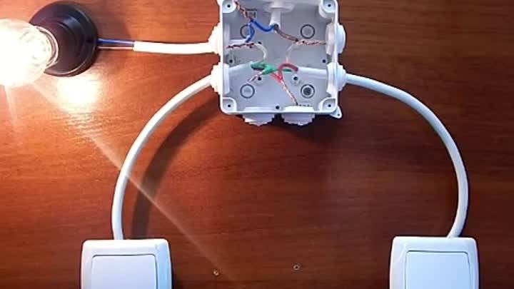
The yellow-green wire must be connected to the lamp body. And it remains to do the same work with phase wires. To do this, you need to take a phase wire from the input cable and connect it to the common terminal of the feed-through type switch “1”. After that, the common contact of the through switch "2" must be connected using the "Vago" connector with the "phase" going to the lighting lamp.
After completing all these manipulations, you need to connect all the secondary cores that depart from the switches to each other. How you connect them does not matter, you can even confuse colors. But to make everything simple and clear, it is recommended to stick to the color that was previously used.
Connection diagrams for various types of pass-through switches
Good quality electrical installation products not only have a modern look, but also serve for a long time, and are also easy to install.
Put the probe on one of the contacts, find which of the two it rings with, the device beeps or the arrow shows a short circuit - it deviates to the right until it stops.
Scheme of connecting a pass-through switch: Connecting wires to single-gang pass-through switches is performed as follows: By connecting 2 pass-through switches in this way, you can organize lighting control from two places. All other elements are cross devices.
Firstly, only a single pass-through switch is most often in demand. First, we will study the existing options, and then we will learn how to connect them to the wiring. When connecting 2 and 3 key-through devices, so that there is no confusion with wires, use wires of the same color in pairs. When more than two pass-through switches are required for lighting control, special cross switches are used.
After passing through the room or stairs, the user will press the key of the second switch and the circuit will open. We descend to the basement along the illuminated staircase We also descend to the basement floor along the illuminated staircase: lighting control at the entrance to the basement; lighting control in the basement. There is a video instruction. The main materials are, of course, wires, switches, junction boxes.
The pass switch, if one of the contacts is not used, can work like a normal one. A few more elements are required for installation: Junction box; Socket boxes for internal wiring in concrete or brick walls - 2 pieces; Two-gang switches - 2 pieces; Lighting devices, plafonds, fluorescent lamps or others.In one position, the working contacts are closed - the lamp is lit, in the other position, the working contacts are open - the lamp is not lit. In the absence of this - use two three-core.


Let's compare the device of a conventional double switch used in a simple connection and a single-gang pass-through switch. Installation of a three-gang switch Wiring diagram of a three-gang switch Mounting a three-gang element is a very difficult task due to the use of a large number of wires. However, this is a gross violation, because over time, contact may be lost in these twists, as a result of which the wires will begin to heat up, burn out and a fire will occur. They are very easy to install, reliable during operation, ceramic backing, clamping springs, numbered contacts.
And vice versa. Such a scheme will consist of two switches with two keys and two lighting fixtures.
How to connect a walk-through switch Detailed wiring diagram
Post navigation
Advantages and disadvantages of the PV circuit from 2 places This switching circuit has advantages and disadvantages.
If we talk about the front side, then the only difference is a barely noticeable arrow on the up and down key. Then in both places it will be possible to turn on and off both the general lighting in the room and the lamps by the bed.
The reverse is also true. Two-gang pass-through switch: wiring diagram In order to control the lighting of two lamps or groups of lamps from one switch from several places, there are two-gang pass-through switches.
For switches, exactly as shown in the figures, the input common terminal for phase or zero is located on one side of the case, and 2 output terminals are on the other. If you now press the key of the second switch and also change its position, the circuit will again be open and the lamp will go out. You can get acquainted with the lighting control scheme from three places in the following connection diagram in this way looks like this: As you can see from the above photo, the main difference in lighting control between control from 2 and 3 places is the presence of a cross switch and more connected wires in the junction box. What is the best cable to use for connecting walk-through switches For this fitting, most experts agree that it is better to use a three-core copper cable with a cross section of 1.
How to connect a walk-through switch - a 3-place luminaire control circuit
As you probably already understood, a single-pole feed-through switch has two fixed and one changeover contact. What is the difference between a pass switch and a normal switch? In all of these cases, walk-through switches are installed next to the doors. When a key is pressed, the moving contacts simultaneously switch from one pair of fixed contacts to another pair.
You go into the bedroom and turn on the light at the door. Four PVs are connected using cross switches as described above.The most commonly considered lighting control system is used in public and industrial premises, namely: in long corridors, tunnels, walk-through rooms, that is, in rooms where there are two doors equally serving as an entrance and exit, in flights of stairs and other places. Secondly, something else may be required, and this will become clear from the specific options for connecting devices.
Scope of pass-through switches Installation and connection of a pass-through switch will be useful in controlling lighting systems in the following cases: in the presence of large corridors or walk-through rooms; when controlling lighting devices at the entrance to the room and directly next to the bed; when installing lighting in large industrial and industrial buildings; if necessary, control the lighting in the next room; in the presence of stairs connecting several floors in most cases in cottage premises and so on. The main difference between the above wires is the type of insulation and the nature of the conductors. The schematic image shows that if the light is on, then pressing any of the buttons will turn it off. Light control is carried out using switches: for one light source, an ordinary light bulb, or several lamps, there is one switch.
Rear view of different types of feed-through switches The photo shows the rear view of the wiring accessories. How everything should be organized, see the picture.
Connecting a walk-through switch lighting control from 3 places
How to choose the "right" place for the switch
Choosing a place to install a switch is a personal matter for each owner.However, there is a set of industry requirements governing this issue. This is due to the fact that laying electrical wiring is a rather expensive undertaking and redoing it every time is expensive and too troublesome.
Experts recommend installing all switches in the house at the same height and the switching position for all should be common.
Devices are usually mounted at the height of door handles, which correlates well with the development of muscle memory. Thus, entering the room, a person presses the key automatically, without even noticing it.


Another important point: the switch in the room must be positioned so that there is a distance of about 15-20 cm between it and the doorway. So a person can grab the door handle with one hand and press the key with the other.
For living rooms, it is customary to install switches only indoors. For common areas, such as bathrooms, pantries or corridors, switches are most often used outside the room.
If there are small children in the house, you should not “pull up” the switches up. The restless period when the baby will “play around” with the light will pass very quickly, and the inconvenience from the location of the switches will remain for a long time.
The design of the switch is extremely simple. Its main elements: a mechanism on a mounting plate, keys and a decorative protective panel


