- Soft start device for incandescent lamps
- Causes of premature burnout
- Principle of operation
- Handmade production of UPVL
- Triac circuit
- Chip based
- They don't act like they usually do.
- thyristor circuit
- Crafts from light bulbs for interior decoration
- Candles
- Fixtures
- decorative fruits
- Slow (smooth) turning on of incandescent lamps
- Circuit options
- In the network 220 V
- At 12 V
- background
- A simple scheme for extending the life of incandescent lamps
- Craft No3 - Christmas tree toy Snowman
- Do-it-yourself soft start device
- Schema selection
- Preparation for work
- Device manufacturing
- Ways to implement soft start
- Power Supply
- Soft start device
- Dimming
Soft start device for incandescent lamps
 A sharp supply of current to an incandescent lamp, the technical characteristics of which were discussed earlier, causes rapid wear - a break in the tungsten filament after it is turned on again. Banal temperature drops - a cold spiral + a sharp current supply - provoke a break due to the low resistance of cold tungsten. The power supply can normalize the temperature regime by slowly and smoothly supplying current.
In a fraction of seconds, the spiral is heated due to the partial supply of current to the lamp, which is enough to heat the metal to increase its resistance.A slow, reduced voltage flow enters the lamp for 3 seconds. Its value gradually increases during this period of time from the minimum value (from zero), for example, to 176 volts. Restrictions on power supply set different.
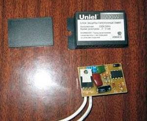
The service life of those equipped with a protection unit is much longer. They are guaranteed to serve you for the maximum period set by the manufacturer. They also use an electronic transformer for halogen lamps - with the same principle of increasing the service life.
It's important to know! There is only one drawback of the protection unit - the flow of light from a lamp with such a device is significantly weakened.
Soft start units have different power limits. Therefore, when buying, it is better to make sure that this model is able to withstand high power surges. That is, the device must have a marginal margin of 30% more than your network supplies.
It is also important to know the total power rating of all the lamps in the house. The power range of units sold today is from 150 to 1000 watts.
Causes of premature burnout
 Dimmer for incandescent lamp
In the vast majority of cases, incandescent lamps burn out when turned on, when the spiral has the lowest electrical resistance. A cold filament has 10 times less resistance than a heated filament. As a result, when the lamp is ignited, the current indicator reaches 8 A, which can be critical for a cold spiral.
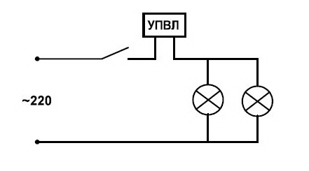
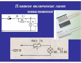
UPVL will help to extend the service life of the light source - the smooth switching on of 220 V incandescent lamps, the circuit of which is simple. The task of such a device is to gradually increase the voltage at the load, sharp current surges in the first seconds after ignition are excluded.Smooth heating of the spiral makes it possible to increase the lamp life by 2-3 times, instead of the declared 1000 hours.
Principle of operation
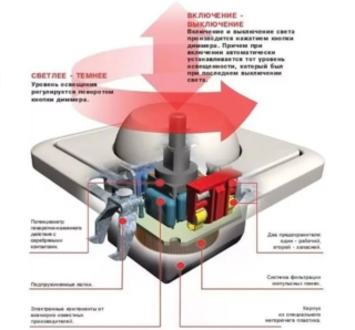 Structure dimmer and working principle
For a measured increase in the applied voltage, it is enough that the phase angle increases in just 2-3 seconds. The current jerk is smoothed out, which contributes to the smooth heating of the spiral.
When the light bulb is lit, a half-wave of the negative type is fed through the diode, while the power indicator is only half the voltage. The charge of the capacitor occurs in the positive half-cycle. When the voltage indicator on it rises to the thyristor opening indicator, the full mains voltage is applied to the light source and it glows in full heat.
Handmade production of UPVL
Of course, all such devices for smoothly turning on incandescent lamps are easy to purchase at any electrical engineering store, but for someone it will be more interesting and informative to assemble it with your own hands. This is quite possible and does not require huge knowledge of physics and electronics. The simplest circuit for switching on the UPVL is based on symmetrical triode thyristors (triacs). It is also easy to manufacture devices based on a specialized microcircuit.
Triac circuit
UPVL scheme using a triac
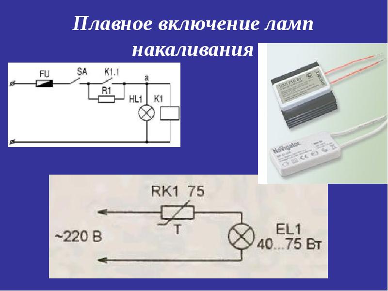
Such a device circuit for smoothly turning on incandescent lamps contains few elements due to the fact that a triac acts as a power key in it (for example, KU208G). In it, although desirable, the presence of a choke is not essential (unlike a more complex circuit based on a simple thyristor). Resistor R1 (in the diagram above) provides current limiting to the triac.The glow time is set by a chain of resistor R2 and a 500 microfarad capacitor, powered by a diode.
When the voltage in the capacitor reaches the opening level of the triac, the current passes through it, starting the consumer (light source). Thus, conditions are created for the gradual ignition of the filament, i.e., the smooth turning on of the light. When the power is turned off, the capacitor slowly discharges, as a result of which the lamp turns off smoothly.


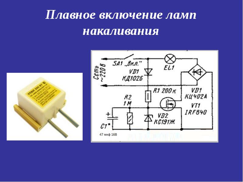
Chip based
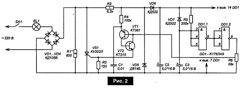
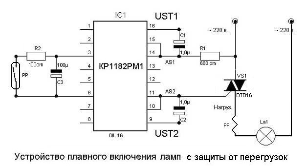
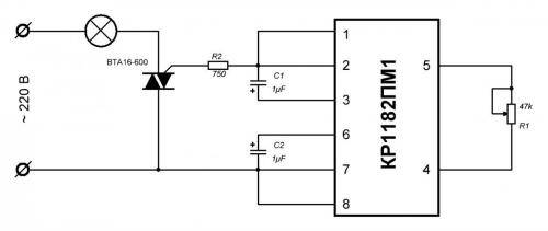
Designed for the manufacture of various regulators, the KR1182PM1 microcircuit is the best suited for assembling a device for smoothly turning on and off incandescent lamps with your own hands. In the case of using such a circuit, practically no efforts will have to be made, since KR1182PM1 will itself regulate the smooth supply of voltage to the lighting fixture up to 150 watts. If the power of consumers is higher, a triac is included in the circuit. Not bad for this purpose BTA 16-600.
UPVL using the KR1182PM1 chip
It makes sense to use such devices not only with incandescent bulbs, but also with 220 V halogen lamps. It is also possible to connect to a power tool for smoother spinning of the rotor. But with fluorescent lamps, as well as with energy-saving ones (CFL), the use of UPVL is not allowed. In their wiring diagram, a similar device is present. You also do not need a soft start device when installing LEDs - LED lamps do not need it due to the fact that there is no filament in them, regardless of whether it is a 24-volt lamp, 220 or 12 volts.
This is interesting: Which spotlights to choose for plasterboard ceilings: we explain in detail
They don't act like they usually do.
Everyone from Mythbusters to National Public Radio has come up with their own explanations for the Shelby light bulb's longevity. But, in general, there is only one answer here - a complete mystery, because the Schieu patent left most of the process unexplained.
Some, like UC Berkeley electrical engineering professor David Tse, openly question the light bulb's authenticity. Others, like engineering student Henry Slonsky, argue that this is most likely due to the fact that once all things were made with a huge margin of safety than they are today. “At that time,” he says, “people were making things far more solid than they needed to be.”
Justin Felgar, one of Dr. Katz's students, further explored the light bulb and published his work in 2010 as The Filament of the Centennial Lamp. In it, Felgar writes that he was able to figure out one curious pattern: the hotter the Shelby lamp heats up, the more electricity passes through the filament of the Centennial Light (which is the exact opposite of what happens with modern tungsten filaments). Felgar claims that in order to determine the exact cause of the Shelby's filament fire resistance, it would be necessary to "tear off one piece" and run it through a particle accelerator at the Naval Academy, but this is a very expensive process, and therefore it is up to still remains verified.
Ultimately, Katz and her colleagues have no definitive answer to this mystery.“I thought that surely all physical processes must eventually come to an end,” she says. “But maybe something happened to this particular light bulb.” Former Deputy Fire Chief Livermore agrees. “The reality is that it’s probably just another mistake of nature,” he told NPR reporters in 2003, “only one in a million light bulbs can continue to glow like this year after year.”
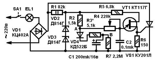
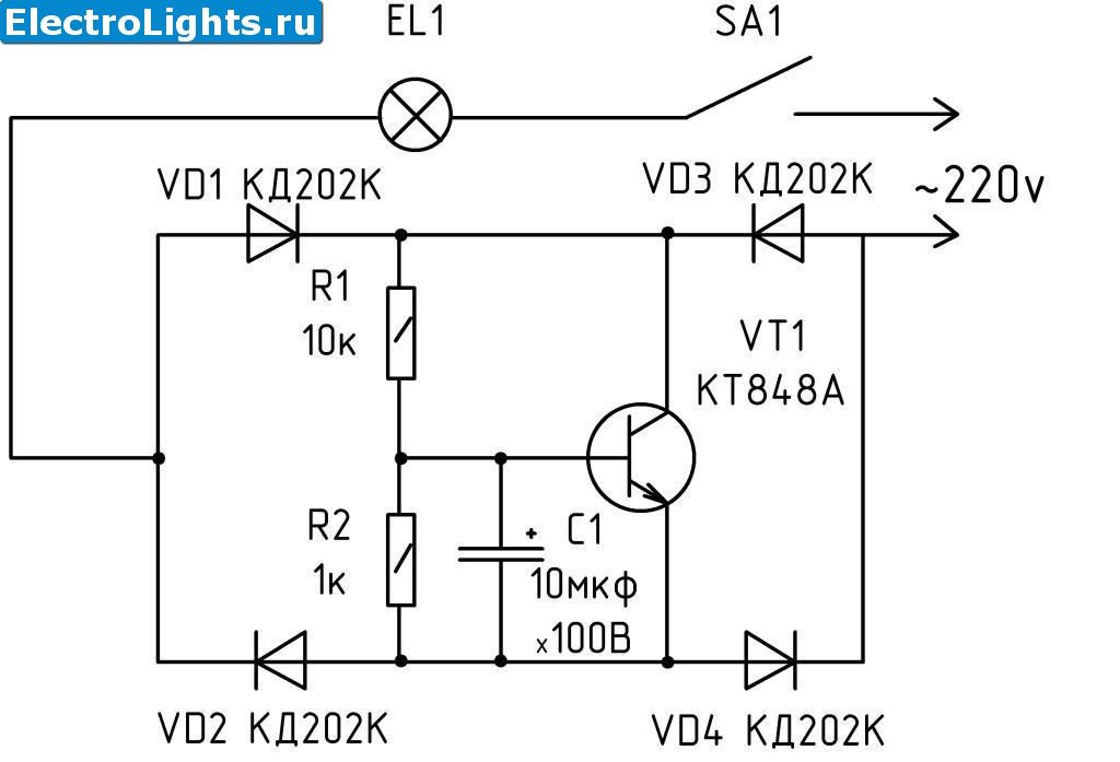
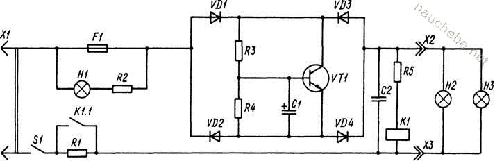
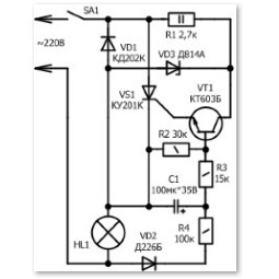
thyristor circuit
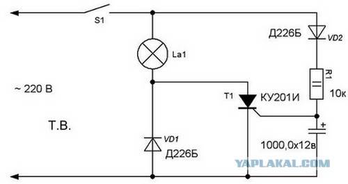
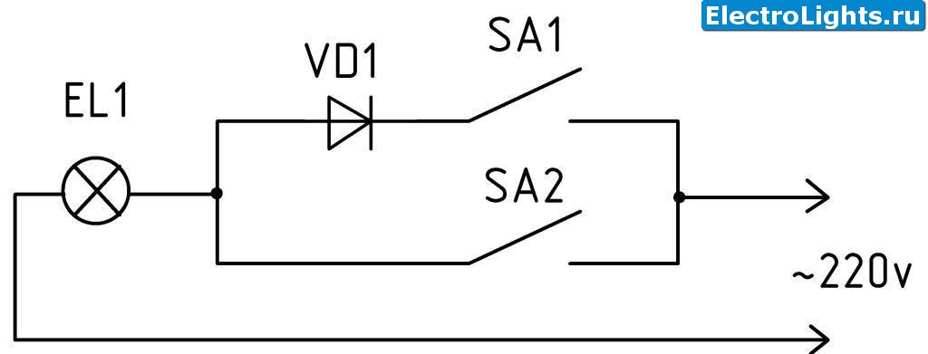
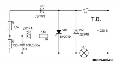
To implement the circuit, you will need simple components, many of which can be found in the pantry at home or in old equipment.
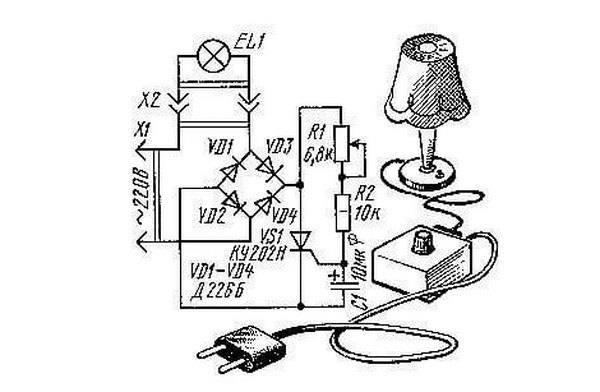
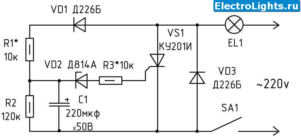
In the chain of the rectifier bridge VD1, VD2, VD3, VD4 there is an incandescent bulb EL1. It performs load and limiter tasks. In the region of the rectifier arm there is a thyristor VS1, as well as a shift circuit R1, R2, C1. The need to install a diode bridge is caused by the peculiarities of the functioning of the thyristor.
Once voltage is applied to the circuit, current is directed through the filament to the rectifier bridge. After that, the electrolyte capacity is recharged through the resistor. When the voltage reaches the moment of opening the thyristor, this device opens. Further, the current of the incandescent lamp flows through the thyristor. As a result, the goal is achieved - the slow heating of the tungsten spiral. The heating rate is set by the capacitance of the capacitor and resistor.
Crafts from light bulbs for interior decoration
Candles
Place a wick in the flask of the lamp, pour melted paraffin. When the paraffin hardens, the glass must be carefully broken and removed. As a result of these actions, you will get an intricately shaped candle.
Fixtures
In the event that you have accumulated a large number of failed lamps, you can store them with benefit by making a lamp out of them. The size and shape of the product can be any and depend only on your taste and fantasy. Mentally imagine the outlines of the lamp. Stick double-sided tape on the bulbs at the points of contact and, as from the details of the designer, assemble a lamp from individual elements, placing a cartridge with a working lamp in the middle. In this technique, you can make both a pendant and a floor lamp.
decorative fruits
The very shape of the light bulb tells us what kind of fruit can be made from it. Of course, first of all it should be a pear. To do this, you only need to wrap the light bulb with the help of twine and glue, decorate it with a green leaf and the craft is ready. Having made several of these fruits, you can put them in a vase, which in itself Can be used as a table decoration.
In such interesting and not very intricate ways, you can find a use for old unnecessary things. And of course, there can be even more of these ways if you allow yourself to dream up properly. And if you introduce children to this kind of activity, then as a big addition to the finished product, you will get a lot of pleasure from communicating with them.
Slow (smooth) turning on of incandescent lamps
Soft start or ignition of incandescent lamps, easy to do with your own hands. There is more than one scheme for this. In some cases, after turning off the voltage supply, the lamps are also smoothly turned off.

Basic schemes:
- Thyristor;
- On a triac;
- Using microchips.
The thyristor connection circuit consists of several main elements. Diode, in the amount of four pieces.The diodes in this circuit form a diode bridge. To ensure the load, use incandescent bulbs.
A thyristor and a shifting chain are connected to the rectifier arms. In this case, a diode bridge is used, as this is due to the operation of the thyristor.
After the start is made, and voltage is applied to the unit, electricity passes through the filament of the lamp and is fed to the diode bridge. Further, with the help of a thyristor, the electrolyte capacity is charged.
After the required voltage is reached, the thyristor opens and current from the lamp begins to flow through it. Thus, there is a smooth start of the incandescent lamp.
The circuit using a triac is simple, since triacs are the power key in the circuit. To adjust the current of the control electrode, use a resistor. The response time is set using several circuit elements, a resistor and a capacitance, powered by a diode.
To operate several powerful incandescent lamps, various microcircuits are used. This is achieved by adding an additional power triac to the circuit. It is worth noting that these circuits work not only with conventional lamps, but also with halogen ones.
Circuit options
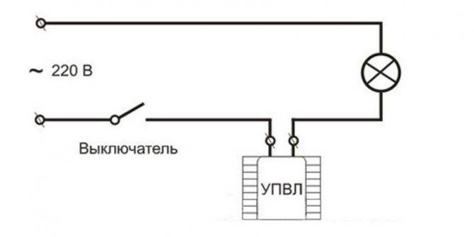
The stores offer a wide selection of soft starters for lamps from Russian and foreign manufacturers. Installation does not require special qualifications. It is necessary to make a break in the phase wire leading to the incandescent lamp, and connect the device using the terminal blocks.
In the absence of terminal blocks, the wires are soldered.
Most often, one of three schemes is used in production:
- tourist;
- triac;
- specialized (usually a KR1182PM1 or DIP8 chip).
In the network 220 V
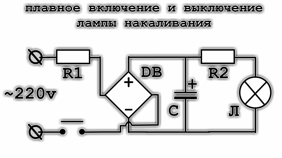
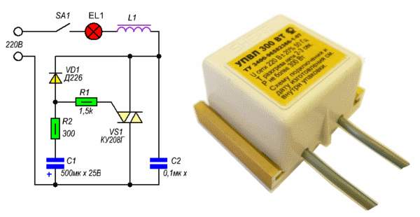
The simplest scheme for smooth switching on lamps is tourist.
For self-production required:
- incandescent lamp;
- 4 diodes (to create a rectifier bridge);
- tourist;
- capacitor (10 uF);
- 2 resistors (one of them variable capacity).
The turn-on time determines the variable resistance.
At the moment of switching on, the current passes through the light bulb, is rectified by the bridge, passes through the resistor and begins to accumulate in the capacitor. After reaching a certain charging threshold, the current is supplied to the tourist, it opens a little. As the condenser fills up, the tourist opens more and more, the light gradually lights up. The maximum light output is reached when the capacitor is fully charged.
Incandescent bulbs are rated for 220 V (in practice it can be up to 240 V). Diodes and tourist are selected based on this indicator. When making it yourself, you need to take into account that you can use any diodes with a voltage of 300 V or more and a tourist that can withstand power from 2 kW. Storage capacity doesn't matter too much.
It is important to know that when it decreases, the bulb will light up faster.
The use of a triac (switch) allows you to reduce the number of elements in the tourist circuit.
Used:
- throttle;
- 2 resistors;
- capacitor;
- diode;
- triac.
According to the principle of operation, this scheme differs little from the previous one. The turn-on time is determined by a chain of a resistor and a capacitor, which are connected through a diode. As the capacitor capacity is filled, the triac gradually opens, through which the incandescent bulb is powered. It does not light up instantly, but smoothly. Such a device is more convenient to use due to its small size.

Soft start of lamps using devices created on the basis of the KR1182PM1 (DIP8) microcircuit can be used with light sources with a power of up to 150 watts.
The basis of this device is 2 tourists and 2 control systems. The time is controlled by a resistor and a capacitor. The power part is separated from the control part by a triac connected through a current-setting resistor. The work of internal tourists is regulated by 2 external capacitors, an additional capacitor and a resistor protect against interference from the network.
When using this scheme, the light not only turns on smoothly, but also turns off smoothly. The duration of tanning and attenuation is regulated by the selection of the capacitance of the capacitors.
Smooth switching has a significant drawback - a decrease in the brightness of the light flux. To achieve the optimal level of illumination, lamps with maximum power are required.
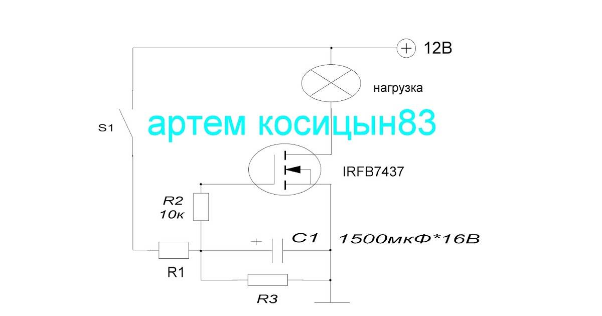
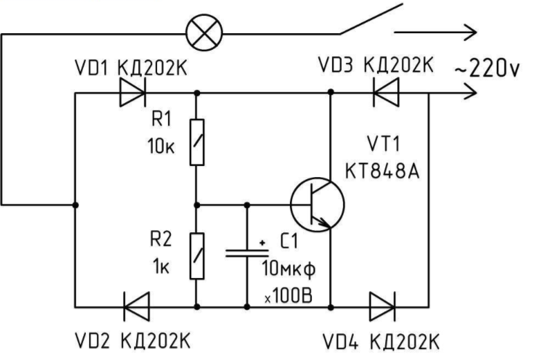
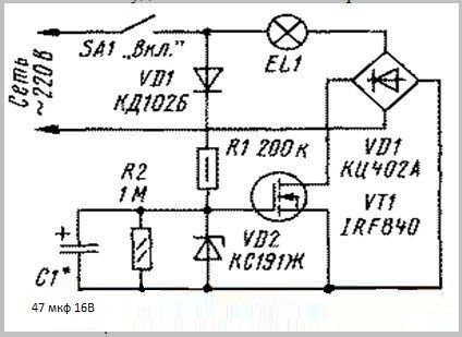
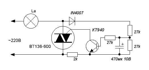
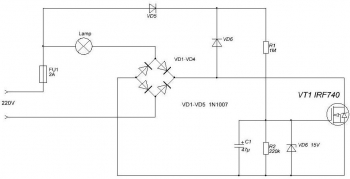
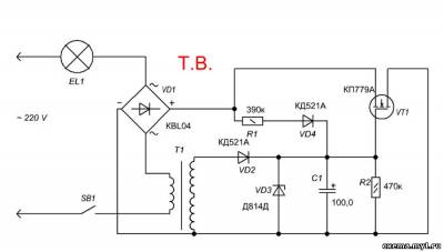
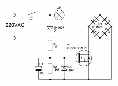
For single-gang switches, there is a transistor-based circuit. When the incandescent bulb is off, it is closed. After switching on, the voltage through the resistor and the diode enters the capacitor, it begins to charge. The maximum level (9.1 V) limits the zener diode.
After reaching the optimum voltage, the transistor begins to open, the filament of a light bulb connected in series gradually heats up. A second resistor is required at the capacitor, which ensures its discharge after turning it off. The main advantage of using a transistor is that the incandescent bulb does not flicker.
At 12 V
If the lamp is point, then a transformer is used that converts 220 volts to 12 volts. For connection to a 12 V soft starter, it is installed in front of the voltage converter.
If such a device is needed for a car, special circuits are required - pulse or linear (PWM controllers).
Linear are connected to light sources in parallel. After switching on, the current passes through the resistor, the lamps are dim. After connecting the relay, they light up at full power.
The resistor should be ceramic, power about 5 W, resistance 0.1-0.5 ohm.
Pulse circuits are created on the basis of a field-effect transistor that supplies current in short pulses. Due to this, the filaments do not heat up to a level at which a break is possible. In the intervals between pulses, the current manages to be evenly distributed along the thread, equalizing the resistance.
background
LED lamps, which are now appearing in almost every home and institution, promise us environmental friendliness and a very long service life, as if big savings. That is, if the good old incandescent lamps served us, or were supposed to last 1000 hours, then the LED ones should work at least 20 thousand hours - 20 times more (hence their high cost follows).
But humanity was in vain disappointed in incandescent lamps. Their short service life is not to blame for the technology, but for the conspiracy of their own manufacturers. As is known from history, the first conspiracy between manufacturers of incandescent lamps took place in 1924. They decided that lamps that were too good were bad. The lamp will burn for a long time, and new ones will be bought less often. Therefore, it was decided to artificially underestimate their service life even in the manufacturing process. They reduced the length of the spiral, reduced the diameter of the supply copper conductors inside the bulb of the lamp, which go from the holders of the spiral to the contacts of the cartridge.Everything, the lamps began to work with overheating, often burn out from a small voltage drop, especially at the moment they are turned on. Very often, even a thin copper conductor inside the lamp burned out, and the spiral itself managed to remain intact. This conspiracy, in turn, not only allowed businessmen to sell inferior products in order to make more money, but became the foundation of the entire modern consumer economy. Therefore, I very much doubt that LED lamps, as they should, will work out their 20,000 hours. They also “fly” no less than their incandescent counterparts, and if it’s still clear with the environment, then there’s no smell of any savings here. But back to incandescent and halogen lamps.
It is well known that halogen lamps and incandescent lamps mostly burn out at the moment they are turned on, when the nichrome coil is in a cold state and has the lowest active resistance. At this point, maximum current will flow through it, especially when the lamp is turned on at the peak of the AC sine wave. But it can be much longer lamp lifeif the filament is heated up gradually, over several seconds.
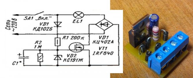
A simple scheme for extending the life of incandescent lamps
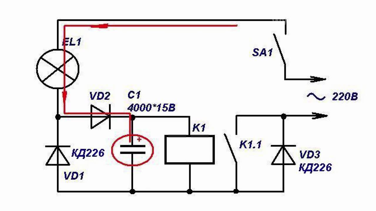
This is a simple lamp soft starter that allows you to significantly reduce the risk of lamp burnout and extend their life.
Incandescent lamps in most cases burn out at the moment of switching on. This is because a cold filament has less resistance than a hot filament. Therefore, at the moment of switching on, the current passing through the lamp is ten times higher than the nominal one. This lasts a short moment, but it is enough to disable the lamp.
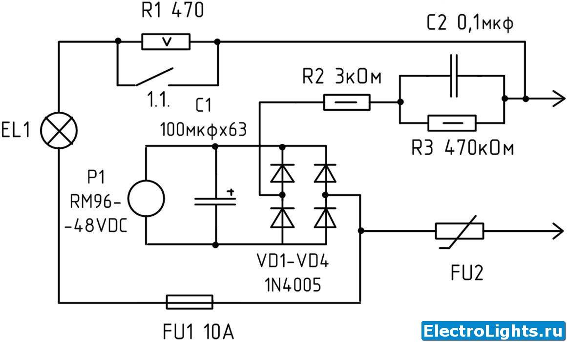
To extend the life of lamps in industrial conditions, soft start systems are used. The presented scheme is the simplest. Here, a relay and a resistor are placed in the break of the existing lamp power circuit. The relay coil is powered in parallel with the lamp. How it works: after turning on the headlights, they light up dimly, like dimensions, and after about half a second they turn on at full power. In this ignition mode, the lamps will live much longer, especially after reheating (+50, +90, etc.).
Would need:
- Relay (for each lamp) - You can use any 12-volt relay for a current of more than 5A, you can also use automotive ones.
- Resistor (nominal 0.1-0.5 Ohm) - is selected individually for the characteristics of the relay, so that the relay operates at the maximum possible resistance value. The resistor needs to use a powerful ceramic about 5 watts.
Placement: two relays can be installed anywhere (for example, under the hood near the headlights or in the fuse box).
This is interesting: Designation of sockets and switches on construction drawings and electrical schemes according to GOST - we consider all the nuances
Craft No3 - Christmas tree toy Snowman
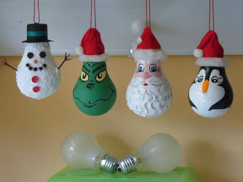
In anticipation of the onset of winter, and with it the New Year holidays, it would be a great idea to spend the evening with your loved ones creating Christmas tree decorations from old light bulbs. This can be done by painting patterns or drawings on the glass surface. You can glue light bulbs using glue with sparkles, rhinestones and small beads. And you can make different figurines.

A win-win option for a Christmas tree toy will be a snowman. To create such a toy you will need:
- old light bulbs
- scraps of fabric
- paints
- polymer clay
- glue
- decorative elements: ribbons, ribbons, ropes, from which you can weave pigtails

Cover the light bulb with white acrylic paint. While it dries, we cut out triangles from the flaps of fabric, sew them in the shape of caps, the edge of which is decorated with a fringe. After that, you can decorate the caps with ribbons, beads and other improvised materials. You can, for example, weave braids from ropes. From polymer clay, mold small carrots that will serve as noses for future snowmen. We paint the noses with orange paint, make black lines, for maximum naturalness. Draw a cute face for the snowman. After drying all the parts, it remains only to connect them with glue. From the rope, make a loop with which the toy will be hung on the Christmas tree, and sew it to the cap.


Do-it-yourself soft start device
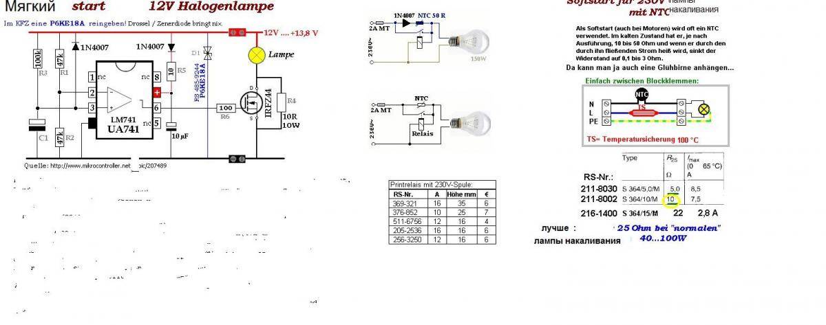
For an experienced craftsman, assembling a device for a soft start of a 220 V incandescent lamp according to the scheme is a matter of several minutes, if all the necessary elements are available. If you are not confident in your abilities, it is better to purchase the product at an electrical engineering store, as improper assembly can damage circuit components.
Before assembly, you must select a scheme. You can take a simple option using thyristors. Specialized microcircuits are also used, which are considered the best for the manufacture of UWL.
Schema selection
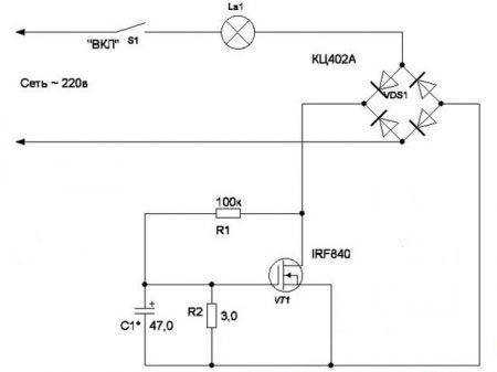
In a circuit with a triac, a small number of elements. It contains a throttle, but not required. Resistor R1 is needed to limit the current supplied to the triac. To set the glow time in the circuit, a resistor R2 with a 500 microfarad capacitor is used.They are powered by a diode.
Triac circuit.
When the triac opens, the current will pass through it and start the light source. This will create conditions for a smooth heating of the spiral. When disconnected, the capacitor slowly discharges.
Another option for manual assembly, which is considered the most common, is the KR1182PM1 chip. She will be able to independently adjust the incoming voltage to a light bulb with a power of not more than 150 watts. If the power is higher, a triac will have to be connected to the circuit.
Scheme KR1182PM1.
This circuit is recommended for halogen and incandescent lamps. It is also suitable for power tools for gradual spinning of the rotor.
Another scheme for assembling UPVL involves the use of a thyristor in it. It is he who is the main functional component. If this option is used for a table lamp or floor lamp, the circuit is placed in the body of the product.
Scheme with a thyristor.
Soft start here occurs by turning the potentiometer knob. Also, this method is used for the controlled switching on of the collector motor, soldering iron or stove.
Preparation for work
When the build option is selected, you need to start preparing. To do this, collect all the necessary elements of the circuit. They can be purchased separately or found in electrical appliances that are no longer in use. Some of the necessary elements can be taken from the devices:
- old TV;
- car charger;
- perforator or drill;
- board for a New Year's garland;
- industrial or household hair dryer.
The triac and thyristor pass the voltage of low and high frequencies. Therefore, they are used for transformer devices in welding machines.
Device manufacturing
If a circuit using a triac is selected, it is worth considering that it passes current in 2 directions, taking into account the passage of part of the rated power. In other words, it can be called an electronic key, the intensity of opening of which depends on the transmitted power. Soft start of incandescent lamps is impossible without the following elements:
- 100 kΩ resistor;
- dinistor;
- another resistor (power 10 kOhm).
Dinistor.
The triac is selected taking into account the load to which the UPVL will be connected. It is also recommended to install a heatsink in the circuit to avoid overheating. Assembly takes place in several stages:

- One of the network wires is connected to the triac, the other to the lamp.
- From the same output, the triac is connected to a variable resistor.
- The second output of the resistor passes through the dinistor, after which the 10 kΩ resistor passes to the second output of the triac.
- The 3rd output of the triac is assigned to the 2nd contact of the light bulb.
- The 3rd contact of the resistor (constant at 100 kOhm) - to the second contact of the lamp.
Turning the installed regulator on a variable resistor, change the output voltage. The lamp starts to light up smoothly in accordance with the adjustment.
Ways to implement soft start
Before deciding how to implement a soft start, it is necessary to understand how HFPLs work. The principle of operation of devices This type is based on the ability to first lower and then gradually increase the voltage to the optimum value. The device is connected to the break in the wire between the lamp (luminaire) and the switch.
When voltage is applied, its value is increased by soft start circuits. They can be assembled on transistors, triacs or thyristors according to FIR schemes (phase-pulse controller).The rate of voltage increase can vary within a few seconds: a lot depends on what scheme the device was assembled according to. The load power most often does not exceed 1400 watts.
Power Supply
The protection unit acts as a device that provides smooth switching. The use of the device simultaneously with the lamp allows you to gradually reduce the voltage supplied to the lighting fixture. In this case, the tungsten filament does not experience a large load, which makes it possible to extend its service life.

As the electrical current passes through the block, the voltage drops (from 220V to 170V). The speed varies within 2-4 seconds. The use of the protection unit for its intended purpose leads to a decrease in the light flux by 50-60%. Uniel Upb-200W-BL devices can withstand up to 220 V, so you need to connect bulbs of the same power to them.
The device can be installed near switches or lighting fixtures.
Soft start device
The mechanism of operation of the soft start device for incandescent lamps (UPVL) is the same as that of the protective blocks. The device has a significant advantage - its small size, so it can be installed in a socket (behind the switch), inside a junction box and a ceiling lamp (under a cap). The UPVL connection must be carried out in series, starting with the connection of the device to the phase conductor.
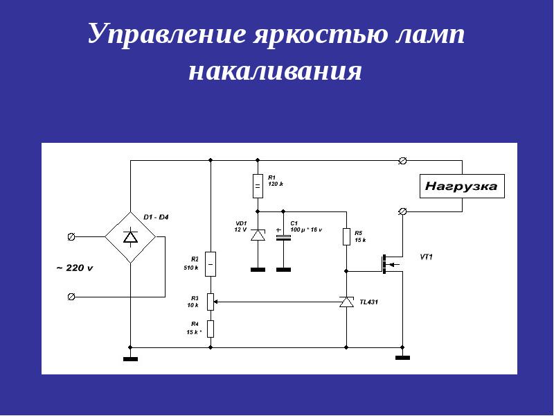
Dimming
Dimmers have the ability to regulate electric current, so these devices are often installed in residential areas. Devices change the brightness of the light that halogen, LED or incandescent lamps give.
A rheostat or variable resistor is considered the simplest dimmer. The device was invented in 1847 by Christian Poggendorf.It can be used to regulate electric current and voltage. The device consists of several parts:
- conductor;
- resistance regulator.
The resistance changes smoothly. To reduce the brightness of the light, the voltage is reduced. In this case, the values indicating the current strength and resistance will be high, which will cause the lighting device to overheat.
Autotransformers are also referred to as dimmers. These devices have a high efficiency. The voltage is supplied undistorted, the optimal frequency is no more than 50 Hz. A significant disadvantage of the autotransformer is a lot of weight. To manage them, a person must make every effort.
The electronic version is the simplest and most affordable device with which you can control the current strength. The main part of the compact device is a switch (key), which is controlled by thyristor, triac and transistor semiconductors.

There are several ways to control the dimmer:
- along the leading edge;
- along the back front.
The voltage supplied to incandescent lamps can be regulated in both ways.


