- Comments:
- Consider making a do-it-yourself solar battery charge controller.
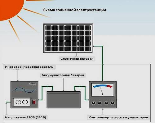
- DIY solar battery charge controller
- Advanced Solar Charge Controller
- Principle of operation
- Self-manufacturing
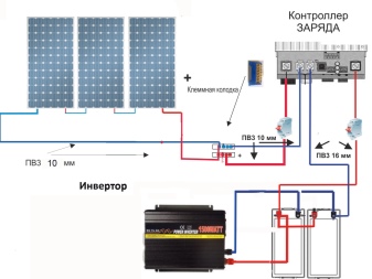
- Module connection diagram
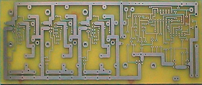
- Device diagram
- Need
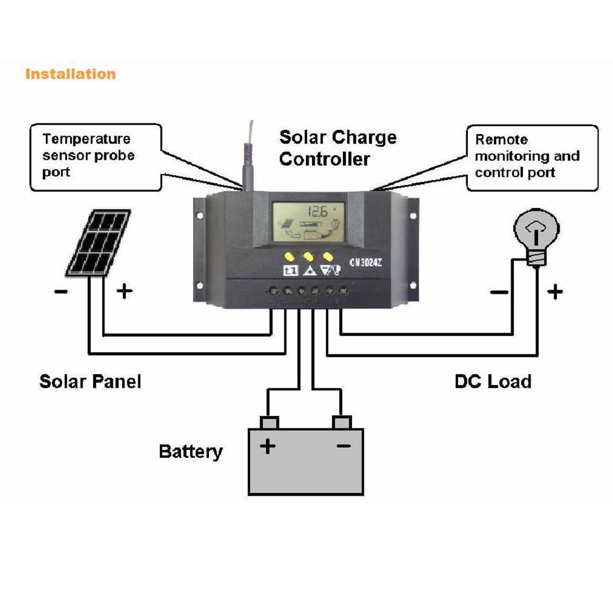
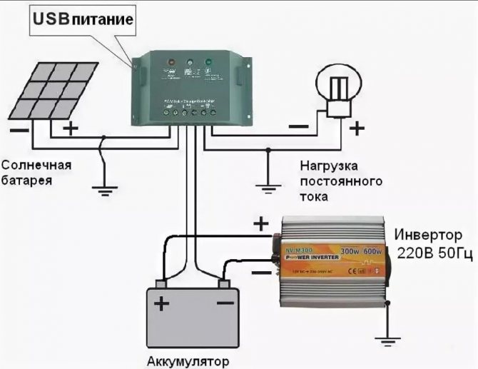
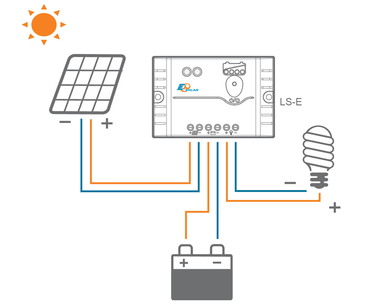
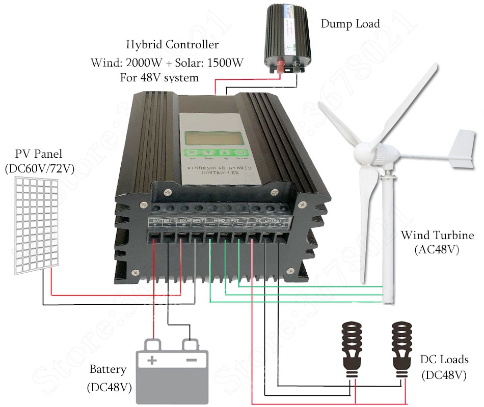
- Wiring diagrams
- serial connection
- Parallel connection
- Series-parallel connection
- The best stationary solar panels
- Sunways FSM-370M
- Delta BST 200-24M
- Feron PS0301
- Woodland Sun House 120W
- Solar connection options
- Need
Comments:

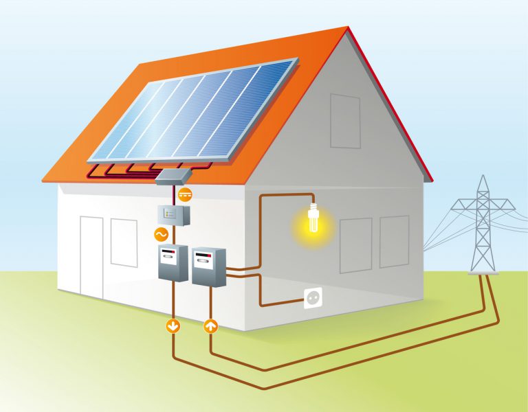
If you have been thinking about an alternative way to get energy and decided to install solar panels, then you probably want to save money. One of the savings opportunities is make your own charge controller. When installing solar generators - panels, a lot of additional equipment is required: charge controllers, batteries, to transfer the current to technical standards.
Consider manufacturing do-it-yourself solar battery charge controller.
This is a device that controls the level of charge of lead-acid batteries, preventing them from being completely discharged and recharged.If the battery begins to discharge in emergency mode, the device will reduce the load and prevent complete discharge.
It is worth noting that a self-made controller cannot be compared in quality and functionality with an industrial one, but it will be quite sufficient for the operation of the electrical network. On sale come across products made in the basement, which have a very low level of reliability. If you do not have enough money for an expensive unit, it is better to assemble it yourself.
DIY solar battery charge controller
Even a homemade product must meet the following conditions:
- 1.2P
- The maximum allowed input voltage must be equal to the total voltage of all batteries without load.
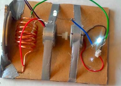
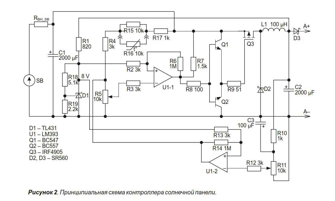
In the image below you will see a diagram of such electrical equipment. In order to assemble it, you will need a little knowledge in electronics and a little patience. The design has been slightly modified and now a field-effect transistor is installed instead of a diode, which is regulated by a comparator.
Such a charge controller will be sufficient for use in low power networks, using only. Differs in simplicity of production and low cost of materials.
Solar charge controller It works according to a simple principle: when the voltage on the storage device reaches the specified value, it stops charging, and only a drop charge continues. If the indicator voltage drops below the set threshold, the current supply to the battery is resumed. The use of batteries is disabled by the controller when their charge is less than 11 V. Thanks to the operation of such a regulator, the battery will not spontaneously discharge during the absence of the sun.
Main characteristics charge controller circuits:
- Charge voltage V=13.8V (configurable), measured when there is a charge current;
- Load shedding occurs when Vbat is less than 11V (configurable);
- Turning on the load when Vbat=12.5V;
- Temperature compensation of charge mode;
- The economical TLC339 comparator can be replaced with the more common TL393 or TL339;
- The voltage drop on the keys is less than 20mV when charging with a current of 0.5A.
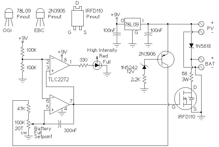
Advanced Solar Charge Controller
If you are confident in your knowledge of electronic equipment, you can try to assemble a more complex charge controller circuit. It is more reliable and is able to run on both solar panels and a wind generator that will help you get light in the evenings.

Above is an improved do-it-yourself charge controller circuit. To change the threshold values, trimming resistors are used, with which you will adjust the operating parameters. The current coming from the source is switched by the relay. The relay itself is controlled by a field effect transistor key.
All charge controller circuits tested in practice and have proven themselves over the course of several years.
For summer cottages and other objects where a large consumption of resources is not required, it makes no sense to spend money on expensive elements. If you have the necessary knowledge, you can modify the proposed designs or add the necessary functionality.
So you can make a charge controller with your own hands when using alternative energy devices. Do not despair if the first pancake came out lumpy. After all, no one is immune from mistakes. A little patience, diligence and experimentation will bring the matter to an end. But a working power supply will be an excellent reason for pride.
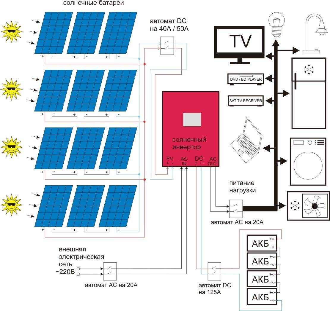
The charge controller is a very important part of the system in which the electric current is generated by solar panels. The device controls the charging and discharging of batteries. It is thanks to him that the batteries cannot be recharged and discharged so much that it will be impossible to restore their working condition.
Such controllers can be made by hand.
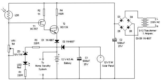
Principle of operation
If there is no current from the solar battery, the controller is in sleep mode. It does not use any of the watts from the battery. After sunlight hits the panel, electric current begins to flow to the controller. He must turn on. However, the indicator LED, together with 2 weak transistors, turns on only when the voltage reaches 10 V.
After reaching this voltage, the current will pass through the Schottky diode to the battery. If the voltage rises to 14 V, the amplifier U1 will start to work, which will turn on the MOSFET transistor. As a result, the LED will go out, and two non-powerful transistors will close. The battery will not charge. At this time, C2 will be discharged. On average, it takes 3 seconds. After the capacitor C2 is discharged, the hysteresis U1 will be overcome, the MOSFET will close, and the battery will begin to charge. Charging will continue until the voltage rises to the switching level.


Self-manufacturing
If a person has certain knowledge in the field of electronics and electrical engineering, then you can try to assemble a controller circuit for solar panels and a wind generator with your own hands.Such a unit will be much inferior in functionality and efficiency to industrial serial samples, but in low-power networks it may be quite enough.
The handicraft control module must meet the basic conditions:
- 1.2P ≤ I × U. This equation uses the notation of the total power of all sources (P), the output current of the controller (I), the voltage in the system with a completely discharged battery (U),
- The maximum input voltage of the controller must correspond to the total voltage of the batteries without load.
The simplest scheme of such a module will look like this:
The device, assembled by hand, works with the following characteristics:
- Charging voltage - 13.8 V (may vary depending on the current rating),
- Cut-off voltage - 11 V (configurable),
- Turn-on voltage - 12.5 V,
- The voltage drop across the keys is 20 mV at a current value of 0.5A.
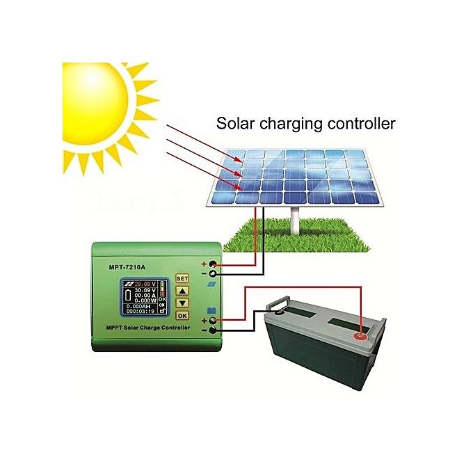
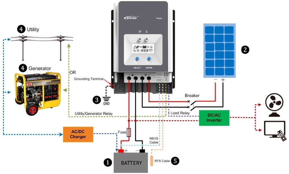
PWM or MPPT type charge controllers are one of the integral parts of any solar or hybrid system based on solar and wind generators. They provide a normal battery charge mode, increase efficiency and prevent premature wear, and can be completely assembled by hand.
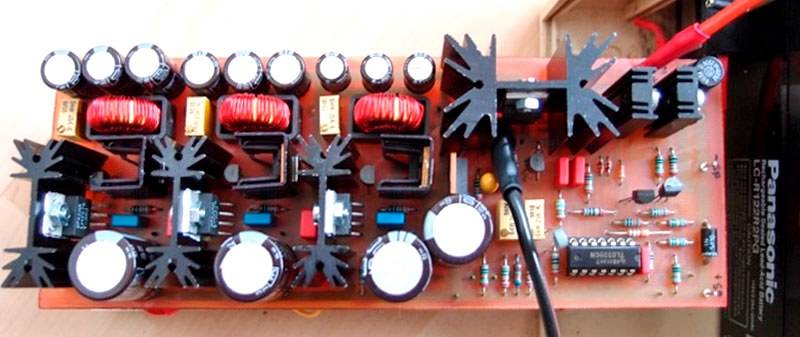
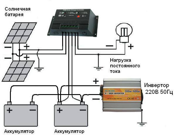
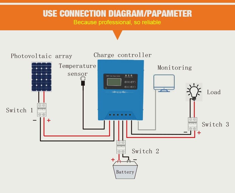
Module connection diagram

Click to enlarge diagram
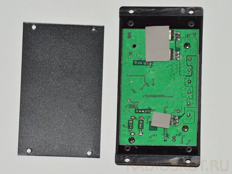
After removing the back wall, you can access the circuit board of the device.
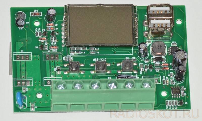
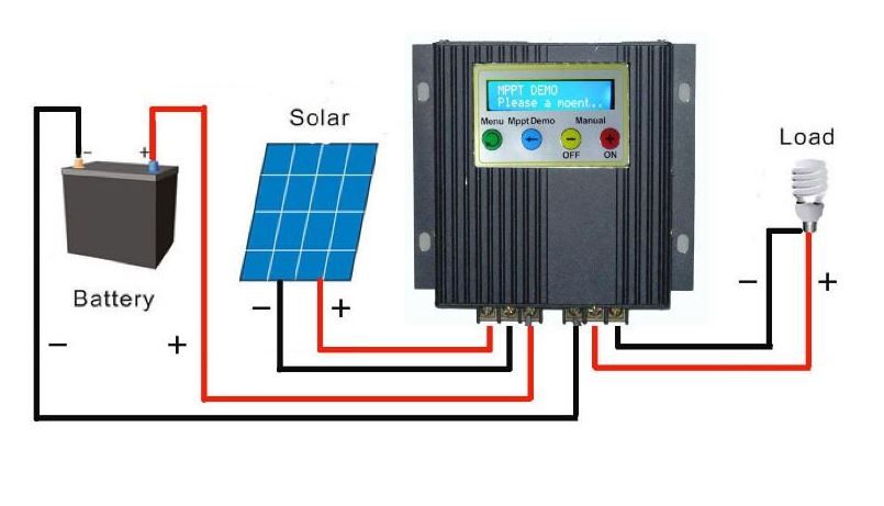
A 12 V battery with a capacity of 1.2 A / h was chosen as the battery, because the author had it. In fact, on a clear sunny day, the panel will be able to charge 2-3 such batteries. A fuse is included in the battery circuit to reduce the risk of a short circuit.To prevent the battery from discharging through the solar panel in low light, a Schottky diode of the IN5817 type is connected in series with the panel. When the battery is fully charged, the current drawn from the solar panel is about 50mA at 19V.
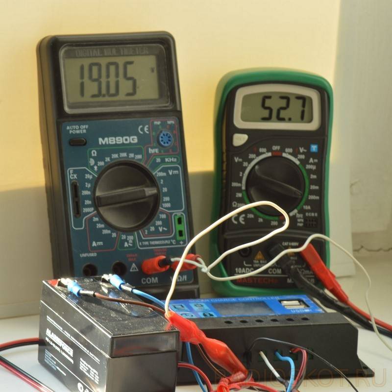
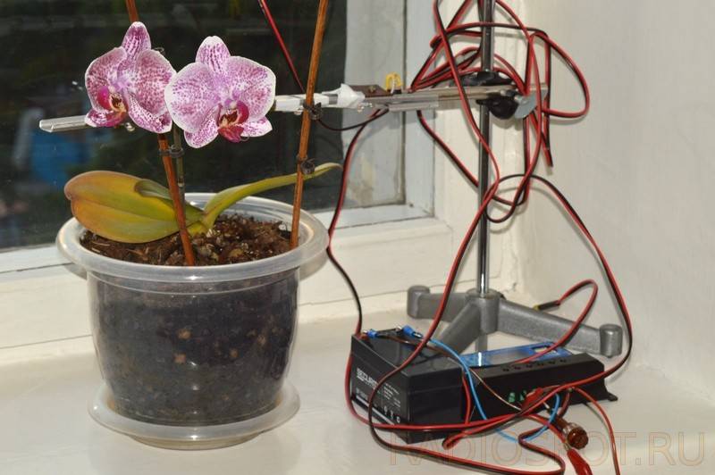
As a test load, a self-made LED phytolamp was used on 4 phyto-LEDs connected in series with a power of 1 W, a resistor of the MLT-2 type with a resistance of 30 Ohm was connected in series with the LEDs. At a voltage of 12.6 V, the current consumed by the lamp will be about 60 mA. Thus, a 1.2 Ah battery allows you to power this lamp for about 20 hours.

In general, the assembled autonomous structure turned out to be quite efficient from a technical point of view. But from an economic point of view, given the cost of the solar battery, battery and control unit, the picture is bleak. A solar battery costs 2700 rubles, a 12 V 1.2 Ah battery costs about 500 rubles, a control unit costs 400 rubles. The author also tried to use two 6 V 12 A / h batteries connected in series (they will cost about 3000 r), the author charges such a battery in 3-4 sunny days, while the charging current reaches 270 mA.
The total cost of used equipment in the minimum configuration is 3600 rubles. As you can see, this phytolamp consumes about 0.8 watts. At a rate of 3.5 r/kWh, the lamp must be operated from the mains at 50% power supply efficiency, about 640,000 hours or 73 years, just to justify the cost of equipment. At the same time, for such a period of time, undoubtedly, it will be necessary to completely change the equipment several times, no one has canceled the degradation of the battery and photocells.


Device diagram
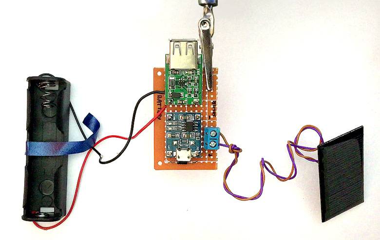
These boards get really hot, so we'll be soldering them a little over the PCB. For this, we will be using a rigid copper wire to make the legs for the PCB. We will have 4 pieces of copper wire to make 4 legs for the circuit board. You can also use pin headers instead of copper wire for this.
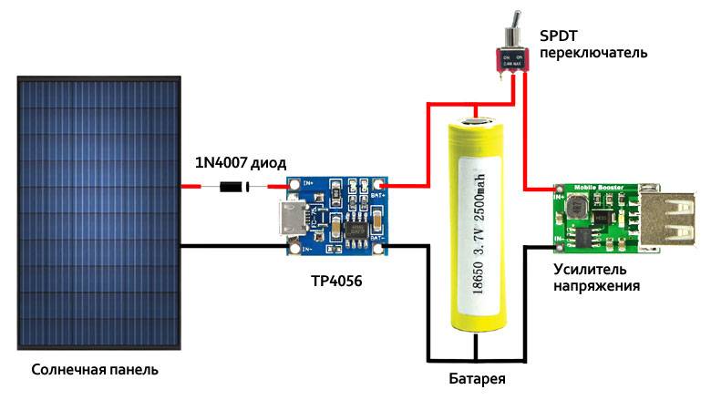
The solar cell is connected to the IN+ and IN- terminals of the TP4056 charging board respectively. A diode is inserted in the positive end for reverse voltage protection. The BAT+ and BAT- boards are then connected to the +ve and -ve ends of the battery. That's all we need to charge the battery.
Now to power the Arduino board, we need to increase the output to 5V. So we add a 5V voltage amplifier to this circuit. Connect -ve batteries to IN- of the amplifier and ve+ to IN+ by adding a switch between them. We connected the booster board directly to the charger, but we recommend installing an SPDT switch there. Therefore, when the device charges the battery, it is charged and not used.
The solar cells are connected to the input of a lithium battery charger (TP4056), the output of which is connected to a 18560 lithium battery. A 5V voltage booster is also connected to the battery and is used to convert from 3.7VDC to 5VDC.
The charging voltage is typically around 4.2V. The voltage booster's input varies from 0.9V to 5.0V. So it will see around 3.7V at its input when the battery is discharging and 4.2V when it is recharging. The amplifier output to the rest of the circuit will keep it at 5V.
This project will be very useful for powering remote data logger. As you know, the power supply is always a problem for the remote recorder, and in most cases there is no outlet available.
A similar situation forces you to use some batteries to power your circuit. But eventually, the battery will die. Our inexpensive project solar charger would be a great solution for this situation.
Need
At the maximum charge of the battery, the controller will regulate the current supply to it, reducing it to the required amount to compensate for the self-discharge of the device. If the battery is completely discharged, then the controller will turn off any incoming load on the device.
The need for this device can be reduced to the following points:
- Battery charging is multi-stage;
- Adjusting the on / off battery when charging / discharging the device;
- Connecting the battery at maximum charge;
- Connecting charging from photocells in automatic mode.
The battery charge controller for solar devices is important because the performance of all its functions in good condition greatly increases the life of the built-in battery.
Wiring diagrams
There are 3 possible schemes for connecting solar panels to each other, these are: serial, parallel and series-parallel connection. Now more about them.
serial connection
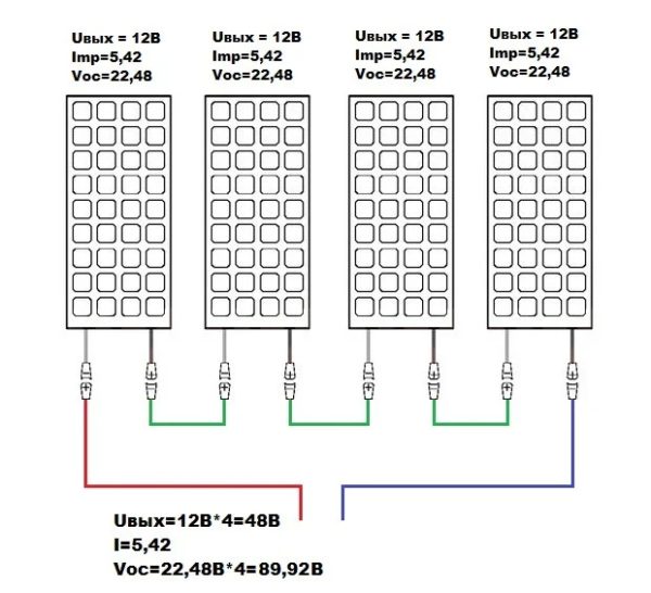
In this circuit, the negative terminal of the first panel is connected to the positive terminal of the second, the negative of the second to the third terminal, and so on. What gives such a connection - the voltage of all panels will be added. In other words, if you want to get, for example, 220V right away, this circuit will help you do it.but it is rarely used.
Let's take an example. We have 4 panels with a rated power of 12V each, Voc: 22.48V (this is the open circuit voltage), we get 48V at the output. Open circuit voltage \u003d 22.48V * 4 \u003d 89.92V. while the maximum current power, Imp, remains unchanged.
In this scheme, it is not recommended to use panels with different Imp values, as the system efficiency will be low.
Parallel connection
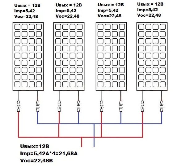
This scheme allows, without raising the voltage of the panels, to increase the current. Let's take an example. We have 4 panels with a rated power of 12V each, open circuit voltage 22.48V, current at the point of maximum power 5.42A. At the output of the circuit, the rated voltage and open circuit voltage remain unchanged, but the maximum power will be 5.42A * 4 = 21.68A.


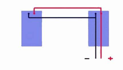
Series-parallel connection
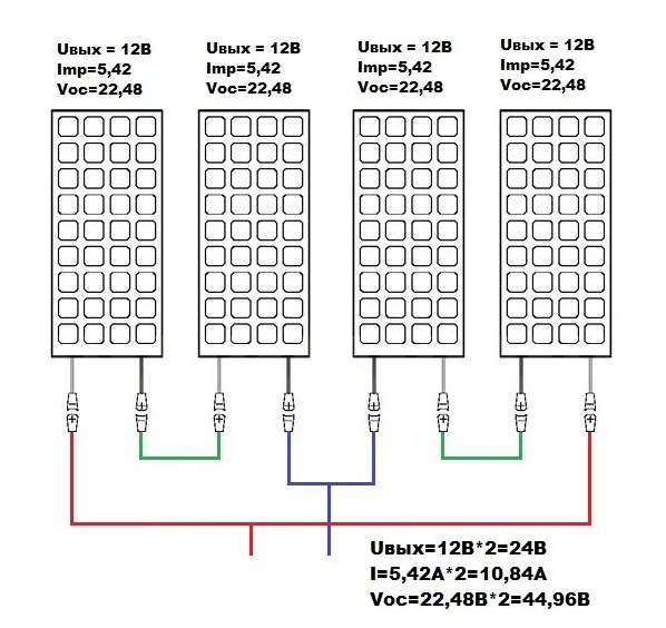
• Nominal solar panel voltage: 12V. • No-load voltage Voc: 22.48V. • Current at maximum power point Imp: 5.42A.
By connecting 2 solar panels in series and 2 in parallel at the output, we get a voltage of 24V, an open circuit voltage of 44.96V, and the current will be 5.42A * 2 = 10.84A.
This makes it possible to have a balanced system and save on equipment such as a battery charge controller, since the emu will not need to withstand a lot of voltage at its peak. The circuit also makes it possible to use panels of different power, for example, 2 to 12V, to convert to 24V. The most convenient network option for the home.
The best stationary solar panels
Stationary devices are characterized by large dimensions and increased power. They are installed in large numbers on the roofs of buildings and other free areas.Designed for year-round use.
Sunways FSM-370M
4.9
★★★★★
editorial score
98%
buyers recommend this product
The model is made using PERC technology, thanks to which it is stable in adverse weather conditions. The anodized aluminum frame is not afraid of sharp impacts and deformation. High-strength tempered glass with low UV absorption ensures the safety of the panel.
Rated power is 370 W, voltage is 24 V. The battery can operate at outdoor temperature from -40 to +85 °С. The diode assembly protects it from overloads and reverse currents, reduces efficiency losses with partial shading of the surface.
Advantages:
- durable corrosion-resistant frame;
- thick protective glass;
- stable operation in any conditions;
- long service life.
Flaws:
great weight.
Sunways FSM-370M is recommended for permanent power supply of large facilities. An excellent choice for placement on the roof of a residential building or office building.
Delta BST 200-24M
4.9
★★★★★
editorial score
96%
buyers recommend this product
A feature of Delta BST is the heterogeneous structure of single-crystal modules. This has improved the panel's ability to absorb scattered solar radiation and ensures its efficient operation even in cloudy conditions.
The peak power of the battery is 200 watts with dimensions of 1580x808x35 mm. Rigid construction withstands difficult conditions, and a reinforced frame with drainage holes ensures stable operation of the panel during bad weather. The protective layer is made of tempered anti-reflective glass 3.2 mm thick.
Advantages:
- stable operation in difficult weather conditions;
- reinforced construction;
- heat resistance;
- stainless frame.
Flaws:
complex installation.
The Delta BST is designed to provide consistent power throughout the year and will provide reliable power for many years to come.
Feron PS0301
4.8
★★★★★
editorial score
90%
buyers recommend this product
The Feron solar panel is not afraid of difficult conditions and functions stably at a temperature of -40..+85 °C. The metal case is resistant to damage and does not corrode. The battery power is 60 W, the dimensions in ready-to-use form are 35x1680x664 millimeters.


If necessary, transport the structure can be easily folded. For convenient and safe carrying, a special case made of durable synthetics is provided. The kit also includes two supports, a cable with clips and a controller, which allows you to immediately put the panel into operation.
Advantages:
- heat resistance;
- stable operation in all weather conditions;
- durable case;
- fast installation;
- convenient folding design.
Flaws:
high price.
Feron can be used in any weather. A good choice for installation in a private home, but you will need several of these panels to get enough power.
Woodland Sun House 120W
4.7
★★★★★
editorial score
85%
buyers recommend this product
The model is made of polycrystalline silicon wafers. Photocells are covered with a thick layer of tempered glass, which eliminates the risk of mechanical damage and external factors. Their service life is about 25 years.
The battery power is 120 W, the dimensions in the ready-to-use state are 128x4x67 centimeters.The kit includes a practical bag made of wear-resistant material that simplifies storage and transportation of the panel. For ease of installation on a flat surface, special legs are provided.
Advantages:
- protective covering;
- fast installation;
- compact size and easy to carry;
- long service life;
- durable bag included.
Flaws:
the frame is flimsy.
Woodland Sun House is capable of charging 12-volt batteries. An excellent solution for installation in a country house, a hunting base and in other places remote from civilization.
Solar connection options
Solar panels are made up of several individual panels. To increase the output parameters of the system in the form of power, voltage and current, the elements are connected to each other, applying the laws of physics.
The connection of several panels to each other can be performed using one of three solar panels mounting schemes:
- parallel;
- consistent;
- mixed.
The parallel circuit involves connecting terminals of the same name to each other, in which the elements have two common nodes of convergence of conductors and their branching.
With a parallel circuit, the pluses are connected to the pluses, and the minuses to the minuses, as a result of which the output current increases, and the output voltage remains within 12 volts
The value of the maximum possible output current in a parallel circuit is directly proportional to the number of connected elements. The principles for calculating the quantity are given in the article we recommend.


The serial circuit involves the connection of opposite poles: the "plus" of the first panel to the "minus" of the second. The remaining unused "plus" of the second panel and the "minus" of the first battery are connected to the controller located further along the circuit.
This type of connection creates conditions for the flow of electric current, in which there is only one way to transfer the energy carrier from the source to the consumer.
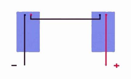
With a serial connection, the output voltage increases and reaches 24 volts, which is enough to power portable equipment, LED lamps and some electrical receivers
A series-parallel or mixed circuit is most often used when it is necessary to connect several groups of batteries. By applying this circuit, both voltage and current can be increased at the output.
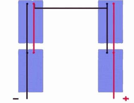
With a series-parallel connection scheme, the output voltage reaches a mark, the characteristics of which are most suitable for solving the bulk of household tasks
This option is also beneficial in the sense that in the event of failure of one of the structural elements of the system, other connecting chains continue to function. This significantly increases the reliability of the entire system.
The principle of assembling a combined circuit is based on the fact that the devices within each group are connected in parallel. And the connection of all groups in one circuit is carried out sequentially.
By combining different types of connections, it will not be difficult to assemble a battery with the necessary parameters. The main thing is that the number of connected cells should be such that the operating voltage supplied to the batteries, taking into account its drop in the charging circuit, exceeds the voltage of the batteries themselves, and the load current of the battery at the same time provides the required amount of charging current.
Need
At the maximum charge of the battery, the controller will regulate the current supply to it, reducing it to the required amount to compensate for the self-discharge of the device. If the battery is completely discharged, then the controller will turn off any incoming load on the device.
The need for this device can be reduced to the following points:
- Battery charging is multi-stage;
- Adjusting the on / off battery when charging / discharging the device;
- Connecting the battery at maximum charge;
- Connecting charging from photocells in automatic mode.
The battery charge controller for solar devices is important because the performance of all its functions in good condition greatly increases the life of the built-in battery.