- Main Functions
- Selectivity tables
- Relay protection - requirements
- Relay protection speed
- Relay sensitivity
- Selectivity of relay protection
- Logic principle
- Time switches
- Further:
- Construction methods and types of selective protection systems
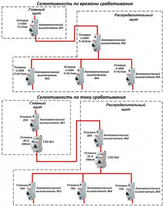
- Current selectivity
- Selectivity by the time interval of protection operation
- Differential principle of constructing selective protection
- Types of selective connection schemes
- Full and partial protection
- Current type selectivity
- Temporal and time-current selectivity
- Energy selectivity of automata
- What is zone selectivity
- Significance and main tasks of selective protection
- Basic definitions
- Benefits of cascading
- Determination of the selectivity of circuit breakers
- Selectivity Map
Main Functions
The key tasks of selective protection are to ensure the uninterrupted operation of the electrical system and the inadmissibility of burning mechanisms when threats appear. The only condition for the correct operation of this type of protection is the consistency of the protective units with each other.
As soon as an emergency situation arises, the damaged section is instantly identified and switched off with the help of selective protection.At the same time, serviceable places continue to work, and disabled ones do not interfere with this in any way. Selectivity significantly reduces the load on electrical installations.
The basic principle of arranging this type of protection lies in the equipment of automatic machines with a rated current that is less than that of the device at the input. In sum, they can exceed the face value of the group machine, but individually - never. For example, when installing an input device of 50 A, the next device should not have a rating higher than 40 A. The unit that is as close as possible to the place of emergency will always work first.
Thus, the main functions of selective protection include:
- ensuring the safety of electrical appliances and workers;
- quick identification and shutdown of the zone of the electrical system where the breakdown occurred (at the same time, the working zones do not stop functioning);
- reduction of negative consequences for the working parts of electromechanisms;
- reducing the load on the component mechanisms, preventing breakdowns in the faulty zone;
- Guarantee of uninterrupted working process and constant power supply of high level.
- support for optimal operation of a particular installation.
Selectivity tables
Selective protection works mainly when the rating In of the circuit breaker is exceeded, i.e. with small overloads. With short circuits, it is much more difficult to achieve it. To do this, manufacturers sell products with selectivity tables, with which you can create links with selectivity. Here you can select device groups from only one manufacturer. Selectivity tables are presented below, they can also be found on the websites of enterprises.
To check the selectivity between the upstream and downstream devices, the intersection of the row and column is found, where “T” is full selectivity, and the number is partial (if the short-circuit current is less than the value indicated in the table).
Relay protection - requirements
Relay protection must comply with a number of requirements, which contain the following principles: the principle of selectivity, sensitivity, reliability, speed. The device must monitor the operation of electrical appliances, respond in time in case of violation of the established mode, immediately turn off the faulty section of the circuit, while giving a signal to the maintenance personnel about an emergency.
Relay protection speed
The response time depends on this requirement, as a result of which the protection of electrical appliances. The sooner the protective relay works, thereby protecting the electrical equipment from damage. Therefore, all electrical equipment must be equipped with relay protection. In this case, the shutdown time is from 0.01 to 0.1 seconds.
Simply put, this is the speed at which the protective relay must detect and disconnect damaged elements. The speed factor is the length of time that starts from the moment a fault occurs and until the faulty element is disconnected from the electrical network.
Acceleration of fault shutdown shortens the time the load operates at reduced voltage, thereby reducing damage to the faulty component. As a result, for an electric network with a voltage of 500 kV, the speed should correspond to 20 ms, and for an electric line of 750 kV - at least 15 ms.
Relay sensitivity
This requirement should ensure the protection of electrical equipment even at minimum rates. That is, it is the susceptibility of the relay to the types of faults for which it is intended.
The sensitivity coefficient is the ratio of the minimum value of the indicator, which was formed as a result of damage, to the set value.
Selectivity of relay protection
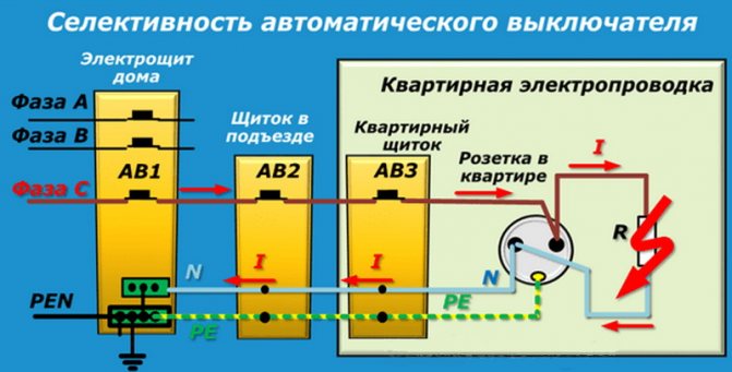
This principle lies in the fact that in the event of a short circuit, only that section of the circuit on which this situation has formed will turn off. All remaining electrical equipment remains in working condition.
Selectivity is divided into absolute and relative. Absolute selectivity is valid only in the area of performance of its functions. Absolute selectivity includes all types of differential protection. The relative characteristic operates on the entire power line, while de-energizing not only its sections, but also neighboring ones. This selectivity includes distance and overcurrent protection.
Logic principle
To implement circuits using this principle, digital relays are needed. The relays are connected to each other by a twisted pair line, a fiber optic cable or a telephone line (using a modem). With the help of such lines, information is received (transmitted) to the control panel from different objects and between the relays themselves.
The principle of logic in a radial network
On the given Picture 9, the principle of operation of logic is explained. Each of the 4 digital relays applies a current setting equal to the most recent sensitive stage. This stage has a response time of 0.2 s. Logic selectivity implies the possibility of blocking the relay with a LO (logical wait) signal.Such a signal is fed through the channel from the previous protection relay. Each of the relays can transmit such signals in transit.


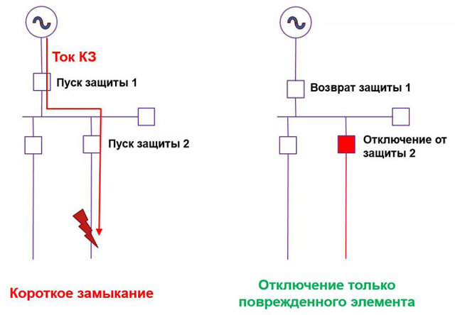
As can be seen from the figure, in the event of a short circuit at point K1, all other relays, from the LO signal given by relay K1, will be waiting. Relay K1 will energize and trip. In the event of a short circuit at point 2, relay K4 will operate in the same way.
Such schemes for constructing logical control are demanding on the reliability of communication lines between elements.
Time switches
Circuit breakers equipped with a mechanism for setting the operating time, regardless of the current value, are called selective. Accordingly, devices that do not have this quality are classified as non-selective. Consider what selectivity is and why it is needed.
Selectivity is one of the main qualities that protection should have. Selectivity lies in the necessary and sufficient amount of protective shutdowns of the damaged section of the network. This means that in the event of damage to the equipment (for example, a short circuit), the protection must work in such a way that only the damaged segment of the circuit is turned off. All other equipment should remain in operation as far as possible. What does the time delay of the switch have to do with this, we will show with an example.
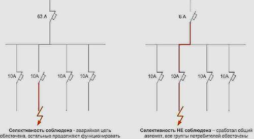
Let's assume that switch "1" is installed on the power input of the 0.4 kV section. Several outgoing lines are fed from this section through linear switches. Let switch "2" be installed on one of the outgoing lines.
Now suppose that a short circuit occurs at the very beginning of this line.Which switch should be tripped by the protections in order to highlight only the damaged area? Of course, "2". But after all, the short circuit current in this situation flows through two switches - "1" and "2" (the short circuit is fed from the source through the input switch "1"). How, then, to ensure that only switch “2” is turned off, because the value of the current flowing through these switches is almost the same. This is where the possibility of setting an artificial shutdown time delay on the automatic input “1” comes to the rescue. At the same time, the protection simply does not have time to work, since the line switch "2" will turn off the short circuit current without time delay.
Further:
- What are surge arresters and where are they used?
- Overview of the voltage relay RN-111, RN-111M, UZM-16.
- Is it better or not inverter voltage stabilizers of other similar devices?
Construction methods and types of selective protection systems
Based on the above principles, the main methods and types of designing selective protection systems are distinguished.
Current selectivity
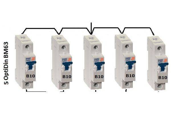
Circuit breakers with different current thresholds are installed in series in the network.
The principle of constructing current selectivity
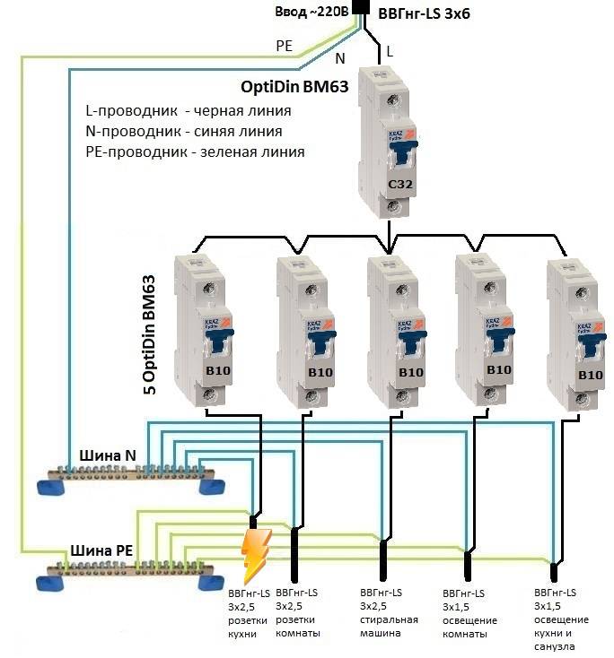
An example would be a network of an ordinary apartment or a private house, when an introductory machine for 25A is installed in the switchboard, after which an intermediate one for 16A. On socket lighting groups or household appliances with a separate line, automatic machines with a response limit of 10A are installed. At the same time, the time and other operating thresholds for these protective switches may be the same or differ depending on the nature of the load.
Current selective protection circuit
Selectivity by the time interval of protection operation
In this case, the construction of protection is carried out according to the same principle as with current protection, only the determining parameter in terms of selectivity is the time of operation of circuit breakers when the threshold value of currents is reached.
Time selective protection scheme
The introductory machine in the switchboard is set to a response interval of 1 second, the intermediate switch has an interval of 0.5 seconds, and before the load itself, automatic machines with a response interval of 0.1 seconds.
- Time-current protection is a set of elements, taking into account the threshold values of operation for current and time, practically a combined option for selecting the parameters listed above;
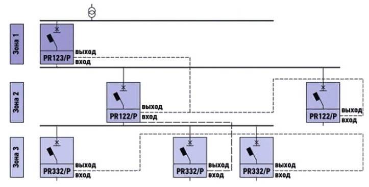
- Zone protection - when the selective protection principle is applied to a separate section of the circuit;
An example of building a zonal protection scheme
The logical principle of constructing selective protection provides for the presence of a processor that receives signals from all protection elements connected in series in the circuit. Based on these data, the device makes a decision and sends a signal to disable the protection element in the area where the threshold of one of the controlled parameters is exceeded;
Scheme of selective protection, built on a logical principle
Selectivity in direction - when protection elements are installed in series in the direction of the current, a phase shift in voltage forms a point in the direction of the voltage vector. Thus, the relay responds to voltage changes and current direction not only in the protection installation area, but also along the entire circuit line from the power source.
In case of a short circuit on the first line, it will be turned off, while the second line will continue to work and, conversely, if a fault occurs on the second line, the first line will not turn off. The disadvantage of this method is that, in addition to circuit breakers, it is necessary to mount voltage transformers for each phase of the line.
Differential principle of constructing selective protection
This method is used in circuits where a load is connected that consumes large electrical power. Current control is carried out by voltage transformers only in the A-B section. In fact, processes are controlled in a short section of the network where the load is connected; when threshold values are exceeded, specific equipment is turned off without affecting other sections.


Differential protection circuit
The advantage of this method is its high speed and sensitivity to changes in parameters; as a disadvantage, the high cost of the equipment can be noted.
All of the above methods of the selective principle of protection construction allow solving a number of problems in the operation of electrical circuits:
- Maintain the operability of serviceable sections during the occurrence of a malfunction in adjacent areas;
- Automatic detection of the fault location and disconnection from the working network;
- Ensuring the safety of personnel serving electrical installations.
When building selective protection, it is necessary to follow the basic principles, all elements are set to the same voltage, at the control points, the smallest and largest values of the parameters in case of a short circuit should be taken into account.
Types of selective connection schemes
Protective equipment by selectivity is divided into several types.These include the following types of protection:
- complete;
- partial;
- current;
- temporary;
- time-current;
- energy.
Each of them needs to be dealt with separately.
Full and partial protection
With such a circuit security, the devices are connected in series. In the event of an overcurrent, the automaton that is closest to the fault will operate.
Important! Partial selective protection differs from full selectivity in that it operates only up to the set overcurrent value.
Current type selectivity
By lining up in descending order the magnitude of the currents from the source to the load, they ensure the operation of current selectivity. The main measure here is the limit value of the current mark.
For example, starting from the power source or input, the circuit breakers are installed in the sequence: 25A, 16A, 10A. All machines can have the same time to operate.
Important! There must be high resistance between the circuit breakers. Then they will have effective selectivity. Increase resistance by increasing the length of the line, including sections with a smaller diameter wire or inserting a transformer winding
They increase the resistance by increasing the length of the line, including sections with a smaller diameter wire or inserting a transformer winding.
Current selectivity
Temporal and time-current selectivity
What does time selective protection mean? A feature of this construction of the relay protection circuit is the binding to the response time of each protective element.Circuit breakers have the same current ratings, but have different tripping delays. The response time increases with distance from the load. For example, the nearest one is designed to operate after 0.2 s. In case of its failure after 0.5 s. the second one should work. The work of the third circuit breaker is rated after 1 second in case of failure of the first two.
Temporal selectivity
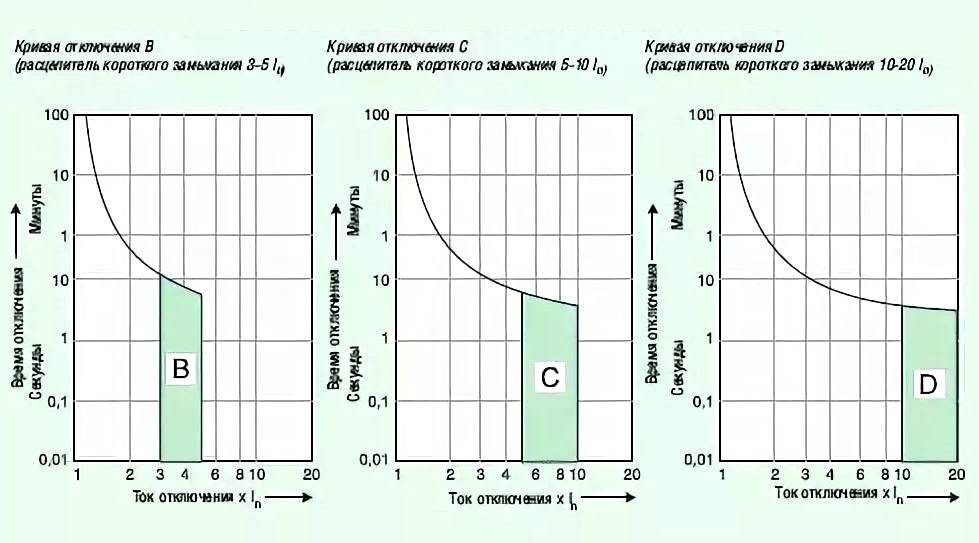
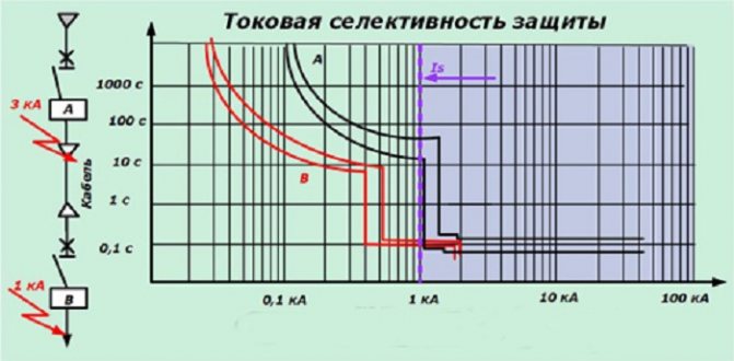
Time-current selectivity is considered very difficult. To organize it, you need to select devices of groups: A, B, C, D. Group A has the highest protection (used in electrical circuits). Each of these groups has an individual response to the magnitude of the electric current and the time delay.

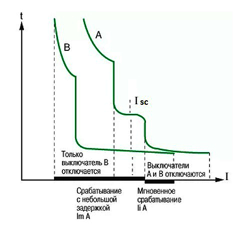


Energy selectivity of automata
Such protection is due to the properties of the switches, which are laid down by the manufacturer. Fast trip - before the short-circuit currents have reached their maximum. The account goes on milliseconds, it is very difficult to agree on such selectivity.
Energy selectivity
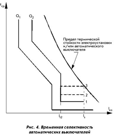
What is zone selectivity
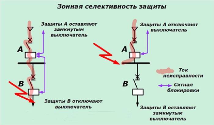
The definition of this coverage by selective protection of the network is associated with the peculiarity of its construction. This is quite an expensive and complicated way. As a result of processing the signals coming from each circuit breaker, the damage zone is determined, and the trip occurs only in it.
Information. For the arrangement of such protection, additional power is required. The signal from each switch is sent to the control center. Trips are made by electronic releases.
Such circuits are most rationally used in industrial enterprises, where systems have high short-circuit currents and significant operating currents.
Example and Graph of Zone Selectivity
Significance and main tasks of selective protection
Safe operation and stable operation of electrical installations are the tasks that are assigned to selective protection. It instantly calculates and cuts off the damaged area without interrupting the power supply to healthy areas. Selectivity reduces the load on the installation, reduces the consequences of a short circuit.
With the smooth operation of circuit breakers, requests are satisfied to the maximum regarding the provision of uninterrupted power supply and, as a result, the technological process.
When the automatic opening equipment fails as a result of a short circuit, the consumers will receive normal power due to selectivity.
The rule stating that the value of the current passing through all distribution switches installed after the introductory machine is less than the indicated current of the latter is the basis of selective protection.
In total, these denominations can be more, but each individual one must be at least one step lower than the introductory one. So, if a 50-ampere automatic machine is installed at the input, then a switch is installed next to it, with a current rating of 40 A.
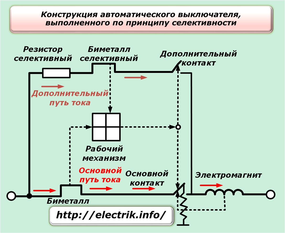
The circuit breaker consists of the following elements: lever (1), screw terminals (2), movable and fixed contacts (3, 4), bimetallic plate (5), adjusting screw (6), solenoid (7), arc chute (8) , latches (9)
Using the lever, both turn on and turn off the current input to the terminals. Contacts are brought to the terminals and fixed. The movable contact with the spring serves for quick opening, and the circuit is connected to it through a fixed contact.
Disengagement, in the event that the current overlaps its threshold value, occurs due to heating and bending of the bimetallic plate, as well as the solenoid.
The operating currents are adjusted using the adjusting screw. In order to prevent the occurrence of an electric arc during the opening of contacts, an element such as an arc chute has been introduced into the circuit. There is a latch to fix the body of the machine.
Selectivity, as a feature of relay protection, is the ability to detect a faulty system node and cut it off from the active part of the EPS.
Here is a diagram of the shield, clearly showing how the load is distributed throughout the apartment. Before installing the machine, you need to calculate the total power of the equipment that will be connected to it
The selectivity of automata is their property to work alternately. If this principle is violated, both circuit breakers and electrical wiring will heat up.
As a result, a short circuit may occur on the line, burnout of fusible contacts, insulation. All this will lead to failure of electrical appliances and a fire.
Suppose there is an emergency on a long power line. According to the main rule of selectivity, the automaton closest to the damage site fires first.


If a short circuit occurs in an ordinary apartment in a socket, the protection of the line, of which this socket is a part, should work on the shield. If this does not happen, it is the turn of the circuit breaker on the shield, and only after it - the introductory one.
Basic definitions
The definition of selectivity is given in GOST IEC 60947-1-2014 "Low voltage distribution and control equipment - Part 1. General rules."
"Selectivity for overcurrents (2.5.23)
Coordination of the operating characteristics of two or more overcurrent protective devices so that in the event of overcurrents within a specified range, only the device designed to operate in this range trips, and the others do not trip”, while overcurrent is understood to be a current with a higher value than the rated current caused by any cause (overload, short circuit, etc.). There is thus selectivity between two circuit breakers in series with respect to the overcurrent that flows through both circuit breakers, with the load side circuit breaker opening to protect the circuit and the supply side circuit breaker remaining closed to supply power to the rest of the installation. Definitions of full and partial selectivity, on the other hand, are given in GOST R 50030.2-2010 "Low voltage distribution and control equipment - Part 2. Circuit breakers."
"Total selectivity (2.17.2)
Overcurrent selectivity, when, when two overcurrent protection devices are connected in series, the device on the load side provides protection without tripping the second protective device.
"Partial selectivity (2.17.3)
Overcurrent selectivity when, when two overcurrent protection devices are connected in series, the device on the load side provides protection up to a certain level of overcurrent without tripping the second protective device.”
One can speak of complete selectivity when selectivity is ensured for any value of overcurrent possible in the installation. Full selectivity between two circuit breakers is said to be when selectivity to the smaller of the Icu values of the two circuit breakers is ensured, since the maximum prospective short circuit current (SC) of the installation will in any case be lower than or equal to the smallest Icu value of the two circuit breakers.
Partial selectivity is said to be when selectivity is provided only up to a certain current value Is (selectivity limit). If the current exceeds this value, then selectivity between the two circuit breakers can no longer be ensured.
Partial selectivity between two circuit breakers is said to be achieved when selectivity is achieved up to a certain Is value, which is lower than the Icu values of the two circuit breakers. If the maximum prospective short circuit current of the installation is less than or equal to the selectivity current Is, one speaks of full selectivity.
Example
The following two circuit breakers are considered:
- On the supply side XT4N250 TMA100 (Icu=36 kA);
- On the load side S200M C40 (Icu=15 kA).
From the “Protection and Control Coordination Tables” it can be seen that full selectivity (T) between two circuit breakers is ensured. This means that selectivity up to 15 kA is provided, i.e. the smaller of the two Icu values.
Obviously, the maximum expected current K3 at the installation site of the S200M C40 circuit breaker will be less than or equal to 15kA.
The following two circuit breakers are now considered:
- On the supply side XT4N250 TMA80 (Icu=36 kA);
- On the load side S200M C40 (Icu=15 kA).
From the "Tables of coordination of protection and control devices" it can be seen that the selectivity between two circuit breakers is Is = 6.5 kA.
This means that if the maximum prospective short-circuit current on the load side of the S200M C40 circuit breaker is less than 6.5 kA, then full selectivity will be provided, and if the short-circuit current is higher, then partial selectivity will be provided, i.e. only for short circuits with currents less than 6.5 kA, while for short circuits with currents between 6.5 and 15 kA, the failure of the supply side circuit breaker is not guaranteed.
Benefits of cascading
Current limiting benefits all downstream circuits which are controlled by the appropriate current limiting circuit breaker.
This principle does not impose any additional restrictions, i. Current-limiting circuit breakers can be installed anywhere in an electrical installation where the downstream circuits are not adequately protected.


Advantages:
- simplification of calculations of short circuit currents;
- a wider choice of downstream switching devices and household appliances;
- the use of switching devices and household appliances designed for lighter operating conditions and, therefore, less expensive;
- space savings, since equipment designed for lower currents is usually more compact.
Determination of the selectivity of circuit breakers
The definition of "selectivity" implies a protective mechanism and the smooth functioning of some devices, consisting of separate parts connected in series with each other.Often, various types of automatic devices, fuses, RCDs, etc. serve as such devices. The result of their work is to prevent the combustion of electrical mechanisms in the event of a threat.
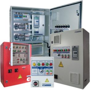
 What does the device look like?
Note! The advantage of this system is its ability to turn off only the necessary sections, while the rest of the system remains in working order. The only condition is the consistency of the protective devices with each other
 Zone protection scheme
Selectivity Map
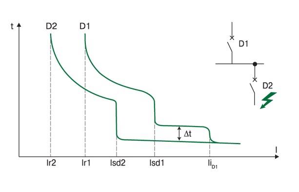
Be sure to mention the selectivity card, which you will need "like air" for overcurrent protection. The map itself is a specific scheme built in axes, where all sets of time-current characteristics of installed devices are displayed. An example is provided below:

We have already said that all protective devices must be connected in turn one after the other. And the map shows the characteristics of these particular devices. The main rules for card drawings are: protection settings must come from one voltage; the scale must be chosen with the expectation that all boundary points will be visible; it is necessary to specify not only the protective properties, but also the maximum and minimum indicators of short circuits at the design points of the circuit.
It should be noted that in today's practice, the absence of selectivity maps in projects is firmly entrenched, especially at low voltages. And this is a violation of all design standards, which in the end is the result of a power outage at consumers.
Finally, we recommend watching a useful video on the topic:


