- How the 555 chip works
- Scope of time relay application
- Time relay diagram | Electrician in the house
- Time relay circuit
- We create a time relay for 12 and 220 volts
- Manufacturing on diodes
- With the help of transistors
- Chip-based creation
- Using ne555 timer
- Multifunction devices
- Scope of application
- The easiest 12V timer at home
- Universal single-channel cyclic timer
- DIY time relay
- 12 Volt
- 220 volt
- Schematic NE555
- On-delay timer
- Cyclic device
- FET timing relay
- Cyclic on-off timer. Do-it-yourself cyclic time relay
- circuit for 12 and 220 volts
- Scope of time relay application
- Schemes of various time relays
- How an electronic timer works
How the 555 chip works
Before moving on to the example of a relay device, consider the structure of the microcircuit. All further descriptions will be made for the NE555 series chip manufactured by Texas Instruments.
As can be seen from the figure, the basis is an RS flip-flop with an inverted output, controlled by outputs from comparators. The positive input of the upper comparator is called THRESHOLD, the negative input of the lower comparator is called TRIGGER. The other inputs of the comparators are connected to a supply voltage divider of three 5 kΩ resistors.
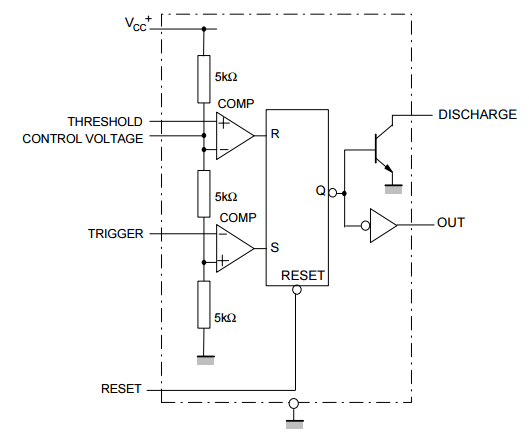
As you probably know, the RS flip-flop can be in a stable state (has a memory effect, 1 bit in size) either in logical "0" or in logical "1". How it functions:
- The arrival of a positive pulse at the input R (RESET) sets the output to logical "1" (namely, "1", not "0", since the trigger is inverse - this is indicated by a circle at the output of the trigger);
- The arrival of a positive pulse at the input S (SET) sets the output to logic "0".
Resistors of 5 kOhm in the amount of 3 pieces divide the supply voltage by 3, which leads to the fact that the reference voltage of the upper comparator (the “-” input of the comparator, it is also the CONTROL VOLTAGE input of the microcircuit) is 2/3 Vcc. The reference voltage of the bottom is 1/3 Vcc.
With this in mind, it is possible to compile state tables of the microcircuit regarding the TRIGGER, THRESHOLD inputs and the OUT output
Note that the OUT output is the inverted signal from the RS flip-flop.
| THRESHOLD < 2/3 Vcc | THRESHOLD > 2/3 Vcc | |
|---|---|---|
| TRIGGER < 1/3 Vcc | OUT = log "1" | indeterminate OUT state |
| TRIGGER > 1/3 Vcc | OUT remains unchanged | OUT = log "0" |
In our case, the following trick is used to create a time relay: the TRIGGER and THRESHOLD inputs are combined together and a signal is supplied to them from the RC chain. The state table in this case would look like this:
| OUT | |
|---|---|
| THRESHOLD, TRIGGER < 1/3 Vcc | OUT = log "1" |
| 1/3 Vcc < THRESHOLD, TRIGGER < 2/3 Vcc | OUT remains unchanged |
| THRESHOLD, TRIGGER > 2/3 Vcc | OUT = log "0" |
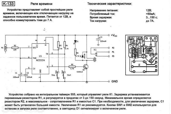
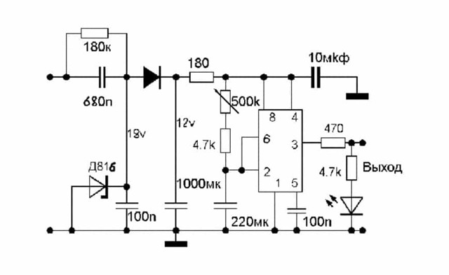
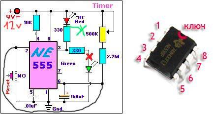
The NE555 wiring diagram for this case is as follows:
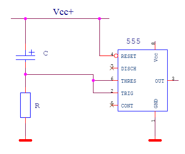
After power is applied, the capacitor begins to charge, which leads to a gradual increase in the voltage across the capacitor from 0V and beyond. In turn, the voltage at the TRIGGER and THRESHOLD inputs will, on the contrary, decrease, starting from Vcc +.As can be seen from the state table, the OUT output is logic "0" after Vcc+ is powered on, and the OUT output switches to logic "1" when the voltage drops below 1/3 Vcc at the specified TRIGGER and THRESHOLD inputs.
It is important that the delay time of the relay, that is, the time interval between power on and charging of the capacitor until the OUT output switches to logic "1", can be calculated using a very simple formula:
Next, we give a drawing of a microcircuit design in a DIP package and show the location of the chip pins:
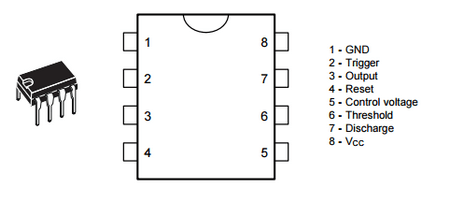
It is also worth mentioning that in addition to the 555 series, the 556 series is produced in a 14-pin package. The 556 series contains two 555 timers.
Scope of time relay application
Man has always sought to make his life easier by introducing various devices into everyday life. With the advent of technology based on an electric motor, the question arose of equipping it with a timer that would automatically control this equipment.
Turned on for a specified time - and you can go do other things. The unit will turn itself off after the set period. For such automation, a relay with an auto-timer function was required.
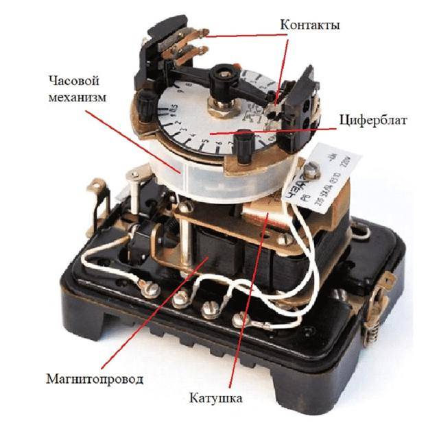
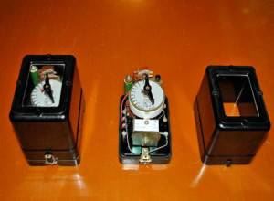
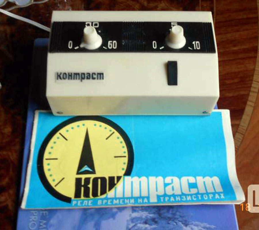
A classic example of the device in question is in a relay in an old Soviet-style washing machine. On its body there was a pen with several divisions. I set the desired mode, and the drum spins for 5-10 minutes, until the clock inside reaches zero.
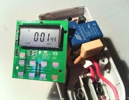
The electromagnetic time relay is small in size, consumes little electricity, has no broken moving parts and is durable
Today, time relays are installed in various equipment:
- microwave ovens, ovens and other household appliances;
- exhaust fans;
- automatic watering systems;
- lighting control automation.
In most cases, the device is made on the basis of a microcontroller, which simultaneously controls all other modes of operation of automated equipment. It's cheaper for the manufacturer. No need to spend money on several separate devices responsible for one thing.
According to the type of element at the output, the time relay is classified into three types:
- relay - the load is connected through a "dry contact";
- triac;
- thyristor.
The first option is the most reliable and resistant to surges in the network. A device with a switching thyristor at the output should be taken only if the connected load is insensitive to the shape of the supply voltage.


To make a time relay yourself, you can also use a microcontroller. However, homemade products are mainly made for simple things and working conditions. An expensive programmable controller in such a situation is a waste of money.
There are much simpler and cheaper circuits based on transistors and capacitors. Moreover, there are several options, there are plenty to choose from for your specific needs.
Time relay diagram | Electrician in the house
Time relay circuit
Time relay circuit
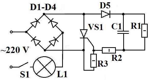
Consider the simplest time relay circuit for 220 volts. This time relay circuit can be used for various needs. For example, with the specified elements, for a photographic enlarger or for temporary lighting of stairs, platforms.
The diagram shows:
- D1-D4 - diode bridge KC 405A or any diodes with a maximum allowable direct rectified current (Iv.max) of at least 1A and a maximum allowable reverse voltage (Uobr.max) of at least 300 V.
- D5 - diode KD 105B or any diode with Iv.max not less than 0.3A and Uobr.max not less than 300V.
- VS1 - thyristor KU 202N or KU 202K(L,M), VT151, 2U202M(N).
- R1 - MLT resistor - 0.5, 4.3 mOhm.
- R2 - MLT resistor - 0.5, 220 Ohm.
- R3 - MLT resistor - 0.5, 1.5 kOhm.
- C1 - capacitor 0.5 uF, 400 V.
- L1 - incandescent lamp(s) not exceeding 200 W.
- S1 - switch or button.
The operation of the time relay circuit
When the contacts S1 are closed, the capacitor C1 begins to charge, “+” is applied to the control electrode of the thyristor, the thyristor opens, the circuit begins to consume a large current and the lamp L1, connected in series with the circuit, lights up. The lamp also acts as a current limiter through the circuit, so the circuit will not work with energy-saving lamps. When the capacitor C1 is fully charged, the current stops flowing through it, the thyristor closes, the lamp L1 goes out. When the contacts S1 open, the capacitor is discharged through the resistor R1 and the time relay returns to its original state.
Finalization of the time relay circuit
With the specified parameters of the circuit elements, the burning time L1 will be 5-7 seconds. To change the response time of the relay, you need to replace the capacitor C1 with a capacitor of a different capacity. Accordingly, with an increase in capacity, the operating time of the time relay increases. You can put two or more capacitors in parallel and connect or disconnect them with switches, in which case you get a stepwise adjustment of the time relay operation. To smoothly adjust the time, you need to add a variable resistor R4. You can combine both methods of adjustment, you get a relay with almost any duration of operation.
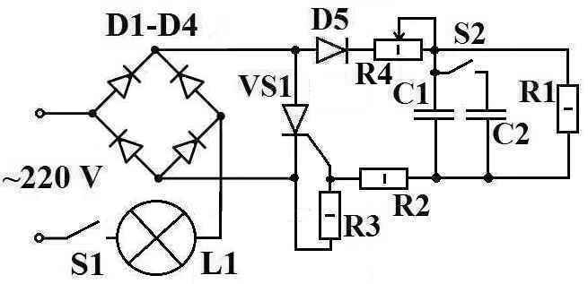
Modified time relay circuit
Schema changes:
- C2 is an additional capacitor, you can take the same one as C1.
- S2 - switch (tumbler) connecting capacitor C2 (increase the operating time of the time relay).
- R4 is a variable resistor, you can take SP-1, 1.0-1.5 kOhm, or close in value.
When prototyping, with the ratings of parts indicated on the diagrams, the light bulb (60W) lit up for about 5 seconds. By adding a capacitor C2 with a capacity of 1 uF and a resistor R4 of 1.0 kOhm to the parallel, it became possible to adjust the burning time of the bulb from 10 to 20 seconds (using R4).
Another time relay circuit can be taken from the article “Automatic Air Freshener”, such a circuit can be used for almost any device.
Be careful when setting up and operating the device, circuit parts are under dangerous voltage.
P.S. Many thanks to Mr. Yakovlev V.M. for help.
It will be interesting to read:
Useful devices, Electronic devices, Wiring diagrams
do-it-yourself, electronics, electrical circuit
We create a time relay for 12 and 220 volts
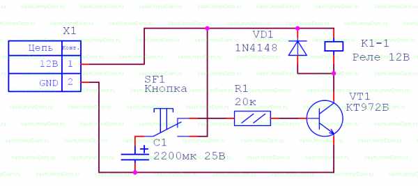
Transistor and microcircuit timers operate at a voltage of 12 volts. For use at loads of 220 volts, diode devices with a magnetic starter are installed.
To assemble a controller with a 220 volt output, stock up:
- three resistances;
- four diodes (current more than 1 A and reverse voltage 400 V);
- a capacitor with an indicator of 0.47 mF;
- thyristor;
- start button.
After pressing the button, the network closes, and the capacitor begins to charge. The thyristor, which was open during charging, closes after the capacitor is charged. As a result, the current supply stops, the equipment is turned off.
Correction is carried out by choosing the resistance R3 and the power of the capacitor.
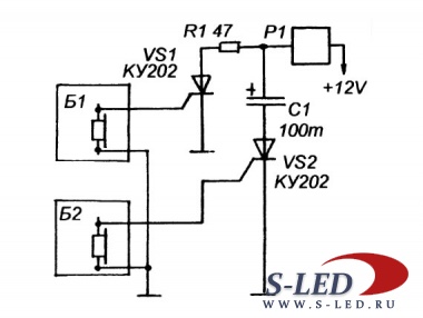
Manufacturing on diodes
To mount the system on diodes, the necessary elements:
- 3 resistors;
- 2 diodes, designed for a current of 1 A;
- thyristor VT 151;
- starting device.
The switch and one contact of the diode bridge are connected to a 220 volt power supply. The second wire of the bridge is connected to the switch. The thyristor is connected to resistances of 200 and 1,500 ohms and a diode. The second terminals of the diode and the 200th resistor are connected to the capacitor. A 4300 ohm resistor is connected in parallel with the capacitor.
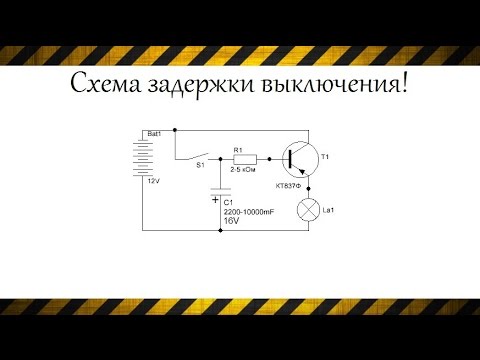
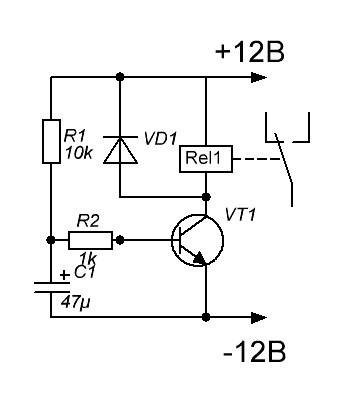
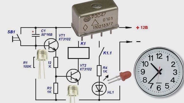
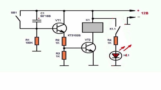
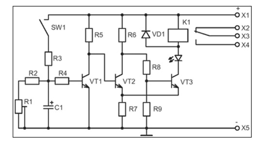
With the help of transistors
To assemble a circuit on transistors, you need to stock up:
- capacitor;
- 2 transistors;
- three resistors (nominal 100 kOhm K1 and 2 models R2, R3);
- button.
After the button is turned on, the capacitor is charged through the resistors r2 and r3 and the emitter of the transistor. In this case, the voltage drops across the resistance, as the transistor opens. After the opening of the second transistor, the relay is activated.


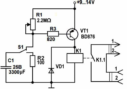
As the capacitance charges, the current drops, and with it the voltage across the resistance to the point at which the transistor closes and the relay is released. For a new start, a complete discharge of the capacity is required, it is performed by pressing a button.
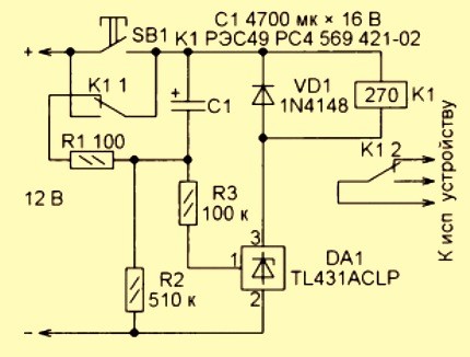
Chip-based creation
To create a system based on chips, you will need:
- 3 resistors;
- diode;
- chip TL431;
- button;
- containers.
The relay contact is connected in parallel with the button to which the “+” of the power source is connected. Second relay contact output to a 100 ohm resistor. The resistor is also connected to resistances.
The second and third pins of the microcircuit are connected to a 510 ohm resistor and a diode, respectively. The last contact of the relay is also connected to a semiconductor, with an executing device. The "-" of the power supply is connected to a 510 ohm resistance.
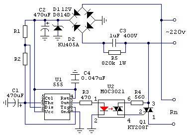
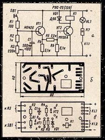
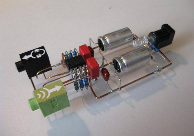
Using ne555 timer
The simplest circuit with an integrated timer NE555, so this option is used in many circuits. To install the time controller you will need:
- board 35x65;
- Sprint Layout program file;
- resistor;
- screw terminals;
- spot soldering iron;
- transistor;
- diode.

The circuit is mounted on the board, the resistor is located on its surface or is output by wires. The board has places for screw terminals. After soldering the components, the excess soldering is removed and the contacts are checked. To protect the transistor, a diode is mounted in parallel with the relay. The device sets the response time. If you connect a relay to the output, you can adjust the load.
- the user presses a button;
- the circuit closes and voltage appears;
- the light comes on and the countdown starts;
- after the set period has elapsed, the lamp goes out, the voltage becomes equal to 0.
The user can adjust the interval of the clock mechanism within 0 - 4 minutes, with a capacitor - 10 minutes. The transistors used in the circuit are bipolar devices of low and medium power of the n-p-n type.
The delay depends on the resistances and the capacitor.
Multifunction devices
Multifunctional time controllers perform:
- countdown in two versions simultaneously within one period;
- parallel counting of time intervals constantly;
- countdown;
- stopwatch function;
- 2 options for autostart (the first option after pressing the start button, the second - after the current is applied and the set period has elapsed).
For the operation of the device, a memory block is installed in it, in which settings and subsequent changes are stored.
Scope of application
In the process of development of human civilization, people have always tried to make life easier for themselves and came up with various useful devices.After the popularization of electrical equipment among the population, it became necessary to invent a timer that would turn off the device after a certain time. That is, you can turn on the unit and go about your business, after which the timer will automatically turn it off at the specified or programmed time. For these purposes, they created a time relay. The 12 V device is characterized by ease of manufacture, so it will not be difficult to make it yourself.
 An example is the relay from an old washing machine, which was popular during the years of the Soviet Union. In the classic version, they had a mechanical round handle with divisions. After scrolling it in a certain direction, the countdown began, and the machine stopped when the timer inside the relay reached the value "zero".
The time relay also exists in modern electrical engineering:
- microwave ovens or other similar equipment;
- automatic watering systems;
- fans for air supply or for exhaust;
- automatic lighting control systems.
This is easier and more economical for the manufacturer, since it is not necessary to install two elements that perform the same function, if all tasks can be provided by one control unit.
All models (both factory and home-made) according to the type of element located at the outlet are divided into:
- relay;
- triac;
- thyristor.
In the first option, the entire load is connected and passes through a "dry contact". It is the most reliable among analogues. For self-manufacturing, you can also use a microcontroller. But doing this is impractical, since ordinary home-made time relays are made for simple tasks.Therefore, the use of microcontrollers is a waste of money. It is better in this case to use simple circuits on capacitors and transistors.
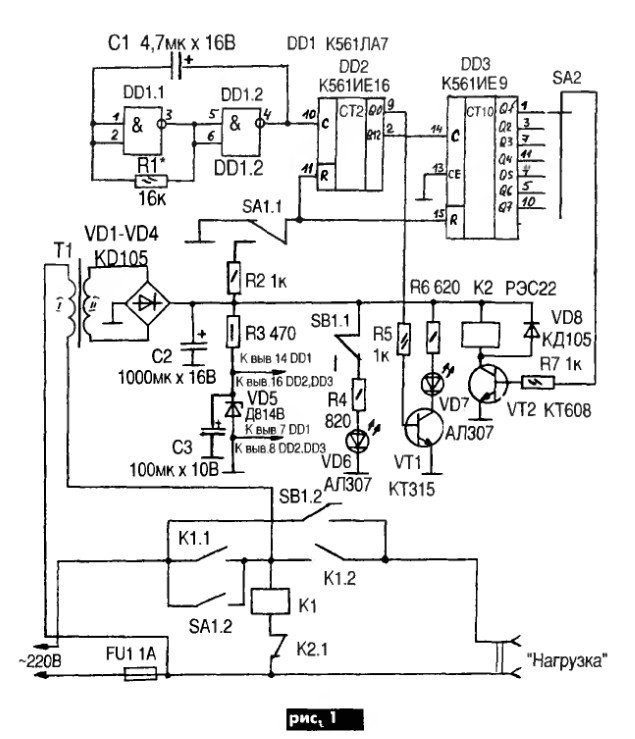
The easiest 12V timer at home
The simplest solution is a 12 volt time relay. Such a relay can be powered from a standard 12v power supply, of which there are a lot of sold in various stores.
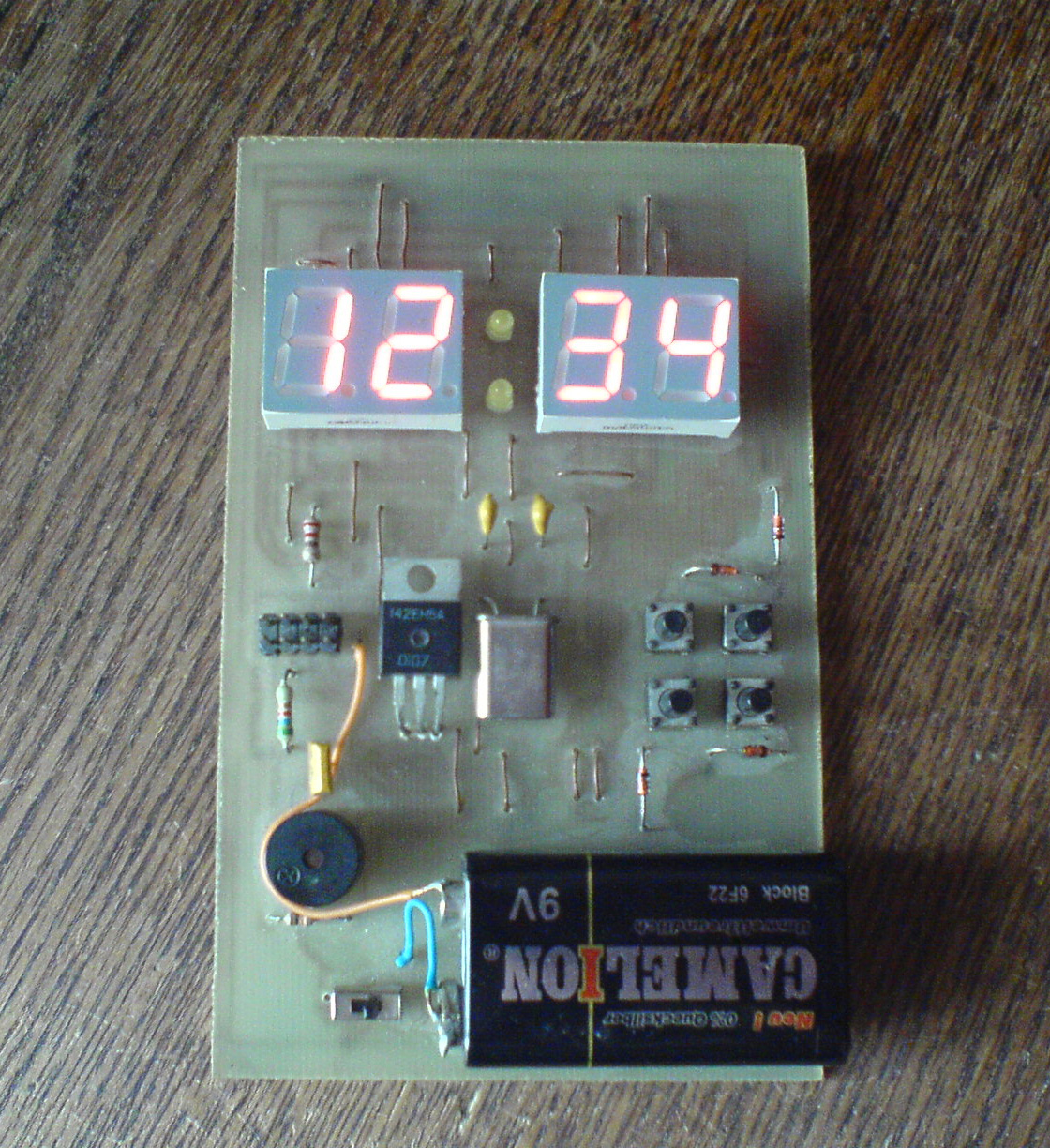
The figure below shows a diagram of a device for turning on and off the lighting network, assembled on one counter of the integral type K561IE16.

Picture. A variant of the 12v relay circuit, when power is applied, it turns on the load for 3 minutes.
This circuit is interesting in that the blinking LED VD1 acts as a clock pulse generator. Its flicker frequency is 1.4 Hz. If the LED of a particular brand cannot be found, then you can use a similar one.


Consider the initial state of operation, at the time of 12v power supply. At the initial moment of time, the capacitor C1 is fully charged through the resistor R2. Log.1 appears on the output under No. 11, making this element zero.
The transistor connected to the output of the integrated counter opens and supplies a voltage of 12V to the relay coil, through the power contacts of which the load switching circuit closes.
The further principle of operation of the circuit operating at a voltage of 12V is to read the pulses coming from the VD1 indicator with a frequency of 1.4 Hz to pin No. 10 of the DD1 counter. With each decrease in the level of the incoming signal, there is, so to speak, an increment in the value of the counting element.
When a 256 pulse arrives (this equals 183 seconds or 3 minutes), a log appears on pin No. 12. one.Such a signal is a command to close the transistor VT1 and interrupt the load connection circuit through the relay contact system.
At the same time, log.1 from output under No. 12 enters through the VD2 diode to the clock leg C of the DD1 element. This signal blocks the possibility of receiving clock pulses in the future, the timer will no longer work, until the 12V power supply is reset.
The initial parameters for the operation timer are set in different ways of connecting the transistor VT1 and the diode VD3 indicated in the diagram.
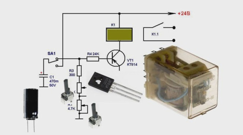
By slightly transforming such a device, you can make a circuit that has the opposite principle of operation. The KT814A transistor should be changed to another type - KT815A, the emitter should be connected to the common wire, the collector to the first contact of the relay. The second contact of the relay should be connected to the 12V supply voltage.

Picture. A variant of the 12v relay circuit that turns on the load 3 minutes after power is applied.
Now, after power is applied, the relay will be turned off, and the control pulse opening the relay in the form of log.1 output 12 of the DD1 element will open the transistor and apply a voltage of 12V to the coil. After that, through the power contacts, the load will be connected to the electrical network.
This version of the timer, operating from a voltage of 12V, will keep the load in the off state for a period of 3 minutes, and then connect it.
When making the circuit, do not forget to place a 0.1 uF capacitor, marked C3 on the circuit and with a voltage of 50V, as close as possible to the supply pins of the microcircuit, otherwise the counter will often fail and the relay exposure time will sometimes be less than it should be.
In particular, this is the programming of the exposure time. Using, for example, such a DIP switch as shown in the figure, you can connect one switch contacts to the outputs of the counter DD1, and combine the second contacts together and connect to the connection point of the VD2 and R3 elements.
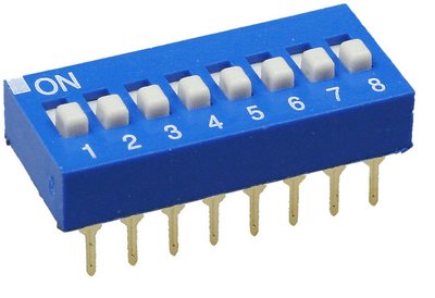
Thus, with the help of microswitches, you can program the delay time of the relay.
Connecting the connection point of the elements VD2 and R3 to different outputs DD1 will change the exposure time as follows:
| Counter foot number | Counter digit number | holding time |
| 7 | 3 | 6 sec |
| 5 | 4 | 11 sec |
| 4 | 5 | 23 sec |
| 6 | 6 | 45 sec |
| 13 | 7 | 1.5 min |
| 12 | 8 | 3 min |
| 14 | 9 | 6 min 6 sec |
| 15 | 10 | 12 min 11 sec |
| 1 | 11 | 24 min 22 sec |
| 2 | 12 | 48 min 46 sec |
| 3 | 13 | 1 hour 37 min 32 sec |
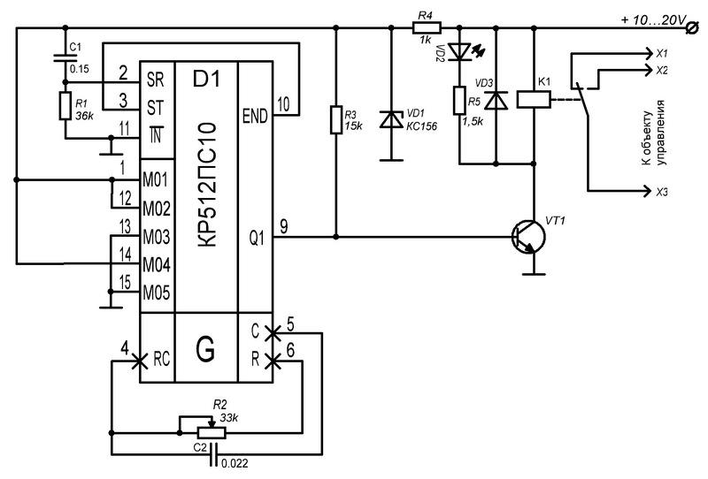
Universal single-channel cyclic timer
Another option: Universal single-channel cyclic timer.
Scheme:
Device capabilities: - adjustable timer cycle duration up to 4 billion seconds (4-byte variable) during firmware. - two actions per cycle (turn the load on and off), set using three buttons. - the ability to turn on / off the load bypassing the timer. - counting discreteness 1 second.- Average current consumption without load 11 microamps (approximately 2 years of operation from CR2032).- Stroke correction (coarse). eats 120uA.
Principle of operation: the timer repeats the recorded actions (on / off) with a certain period (cycle) set by the user in the EEPROM memory when flashing the controller. Task example: you need to turn on the load at 21:00 and turn it off at 7:00, and do this every three days. Solution: we flash the timer with a cycle of "3 days", we start it.The first time we approach the timer at 21:00, hold down the PROG button and without releasing it, press the ON button, the LED will light up for 0.5 seconds and the output will turn on. The second time we approach the timer at 7:00, hold down the PROG button and without releasing it, press the OFF button, the LED will light up for 0.5 seconds and the output will turn off. That's it, the timer is programmed and will perform these actions every three days at the same time. If the load needs to be turned on or off bypassing the timer, you must press the ON or OFF buttons without the PROG button, the program will not fail and the load will turn on / off the next time at the previously set time. You can check the timer's operation by pressing the PROG button, the LED will flash once a second .
Description of testing with different capacitors in the previous article.
For a simpler device setup, a calculator (EEPROM code generator) was also written. With it, you can create a HEX file to replace part of the code in the firmware file.
Update 02/29/2016Configurator 04/16/2016 Forum
DIY time relay
Let's analyze the simplest ways to make do-it-yourself slowdown systems.
12 Volt
We need a printed circuit board, a soldering iron, a small set of a capacitor that performs a relay, transistors, emitters.
The circuit is drawn up in such a way that when the button is turned off, there is no voltage on the capacitance plates. During the short circuit of the button, the capacitor rapidly charges and then begins to discharge, supplying voltage through the transistors and emitters.


In this case, the relay will be closed or open until a few volts remain on the capacitor.
You can regulate the duration of the discharge of the capacitor by its capacitance or by the value of the resistance of the connected circuit.
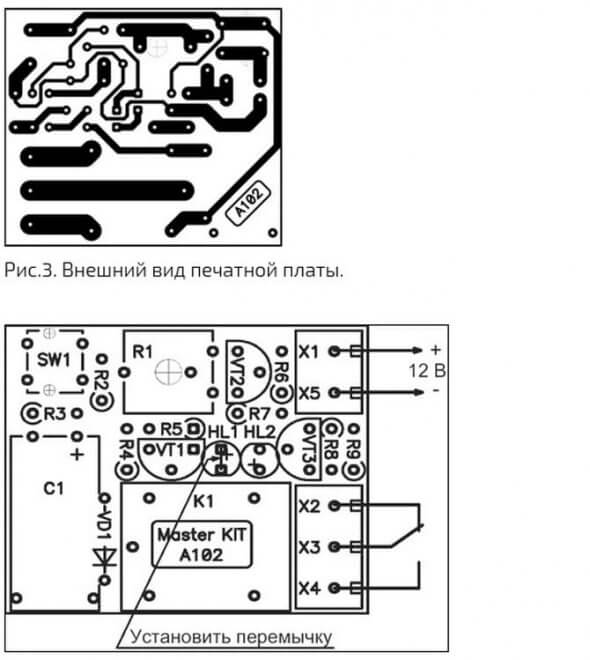
Work order:
- payment is being prepared;
- paths are being tinned;
- transistors, diodes and relays are soldered.
220 volt
Fundamentally, this scheme is not very different from the previous one. The current passes through the diode bridge and charges the capacitor. At this time, a lamp is lit, which acts as a load. Then the process of discharging and triggering the timer takes place. The assembly procedure and the set of tools are the same as in the first option.
Schematic NE555
In another way, the 555 chip is called an integral timer. Its use guarantees the stability of maintaining the time interval, the device does not respond to voltage drops in the network.
When the button is off, one of the capacitors is discharged, and the system can be in this state indefinitely. After pressing the button, the container starts charging. After a certain time, it is discharged through the circuit transistor.
The discharge transistor opens and the system returns to its original state.
There are 3 operating modes:
- monostable. At the input signal, it turns on, a wave of a certain length comes out and turns off in anticipation of a new signal;
- cyclical. At predetermined intervals, the circuit enters the operating mode and turns off;
- bistable. Or a switch (pressed button works, pressed - does not work).
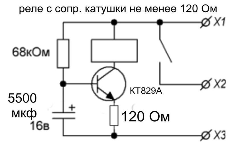
On-delay timer
After the voltage is applied, the capacitance is charged, the transistor opens, while the other two are closed. Therefore, there is no output load. During the discharge of the capacitor, the first transistor closes, the other two open. Power begins to flow to the relay, the output contacts close.
The period depends on the capacitance of the capacitor, variable resistor.
Cyclic device
The most commonly used counters are generators. The first of which generates a signal at specified intervals, and the second receives them, setting a logical zero or one after a certain number of them.
All this is created using a controller, you can find a lot of circuits, but they will require some knowledge of radio engineering.
Another option is to fully discharge or charge the capacitance using a microcircuit, which sends a signal to the control transistor, which operates in key mode.
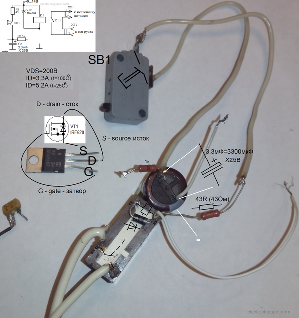
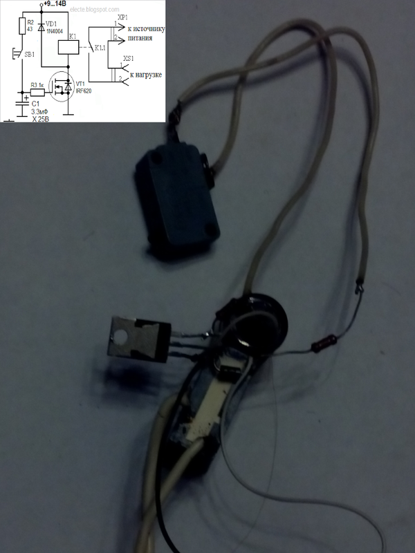
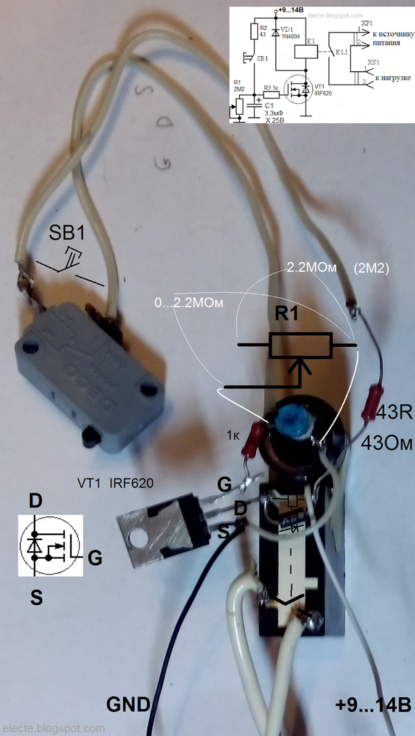
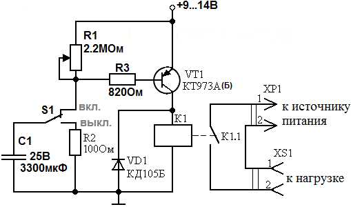
FET timing relay
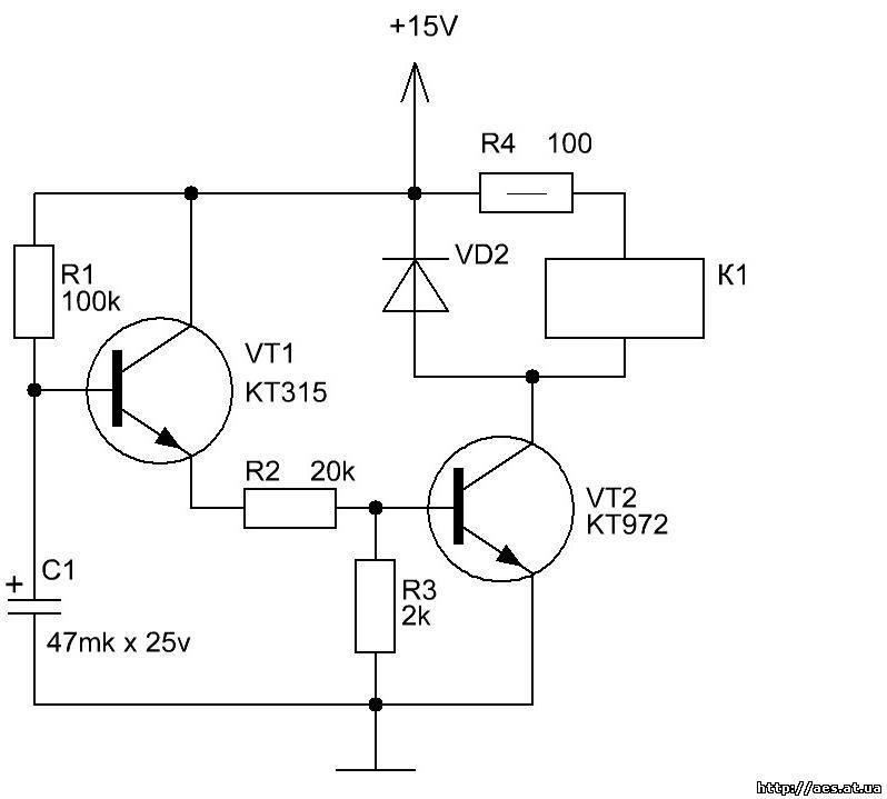
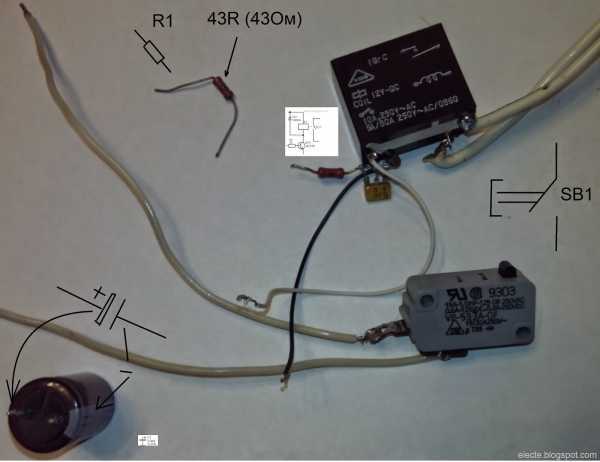
A simple time relay (or a simple time relay for beginners 2) on a bipolar transistor is not difficult to manufacture, but such a relay cannot get large delays. The duration of the delay determines the RC circuit consisting (for a time relay and a bipolar transistor) of a capacitor, a resistor in the base circuit and a base-emitter junction of the transistor. The larger the capacitance, the greater the delay. The greater the total resistance of the resistor in the base circuit and the base-emitter junction, the greater the delay. It is impossible to increase the resistance of the base-emitter junction to obtain a large delay. this is a fixed parameter of the used transistor. The resistance of the resistor in the base circuit cannot be increased indefinitely. to open the transistor requires a current at least h31e less than the current required to turn on the relay. If, for example, 100mA is required to turn on the relay, h31e = 100, then base current Ib = 1mA is required to open the transistor. To open a field-effect transistor with an insulated gate, a large current is not required, in this case, you can even neglect this current and assume that current is not required to open such a transistor.The IGF is voltage controlled so you can use an RC circuit with any resistance and therefore any delay. Consider the schema:
Figure 1 - Time relay on a field-effect transistor
This circuit is similar to the bipolar transistor circuit from the previous article, only here instead of the n-MOSFET bipolar transistor (n-channel insulated gate (and induced channel) bipolar transistor) and a resistor (R1) is added to discharge the capacitor C1. Resistor R3 is optional:
Figure 2 - FET time relay without R3
Insulated gate field-effect transistors can be damaged by static electricity, so they must be handled with care: try not to touch the gate terminal with hands and charged objects, ground the gate terminal if possible, etc.
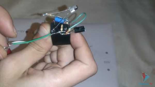
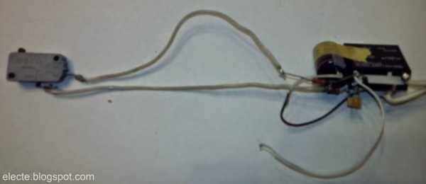
The process of checking the transistor and the finished device is shown in the video:
Because the parameters of the RC circuit are negligibly little affected by the parameters of the transistor, then the calculation of the delay duration is quite easy to carry out. In this circuit, the duration of the delay is still affected by the duration of holding the button and the smaller the resistance of the resistor R2, the weaker this effect, but do not forget that this resistor is needed to limit the current at the moment the button contacts are closed, if its resistance is made too low or replaced jumper, then when you press the button, the power supply may fail or its short circuit protection may work. (if any), the button contacts can fuse to each other, in addition, this resistor limits the current when the minimum resistance is set by resistor R1.Resistor R2 also lowers the voltage (UCmax) to which the capacitor C1 is charged when the SB1 button is pressed, which leads to a decrease in the delay duration. If the resistance of the resistor R2 is low, then it does not significantly affect the duration of the delay. The duration of the delay is affected by the voltage at the gate relative to the source at which the transistor closes (hereinafter referred to as the closing voltage). To calculate the duration of the delay, you can use the program:
BLOG MAP (content)
Cyclic on-off timer. Do-it-yourself cyclic time relay
circuit for 12 and 220 volts
In modern equipment, a timer is often needed, that is, a device that does not work immediately, but after a period of time, so it is also called a delay relay. The device creates time delays for turning other devices on or off. It is not necessary to purchase it in a store, because a well-designed home-made time relay will effectively perform its functions.
Scope of time relay application
Areas of use of the timer:
- regulators;
- sensors;
- automation;
- various mechanisms.
All these devices are divided into 2 classes:
- Cyclic.
- Intermediate.
The first is considered an independent device. It gives a signal after a specified time period. In automatic systems, a cyclic device turns on and off the necessary mechanisms. With its help, lighting is controlled:


- on the street;
- in aquarium;
- in a greenhouse.
The cyclic timer is an integral device in the Smart Home system. It is used to perform the following tasks:
- Turning the heating on and off.
- Event reminder.
- At a strictly specified time, it turns on the necessary devices: a washing machine, a kettle, a light, etc.
In addition to the above, there are other industries in which a cyclic delay relay is used:
- the science;
- the medicine;
- robotics.
Intermediate relay is used for discrete circuits and serves as an auxiliary device. It performs automatic interruption of the electrical circuit. The scope of the intermediate timer of the time relay begins where signal amplification and galvanic isolation of the electrical circuit are necessary. Intermediate timers are divided into types depending on the design:
- Pneumatic. The relay operation after the signal is received does not occur instantly, the maximum operation time is up to one minute. It is used in control circuits of machine tools. The timer controls the actuators for step control.
- Motor. The time delay setting range starts from a couple of seconds and ends with tens of hours. Delay relays are part of overhead power line protection circuits.
- Electromagnetic. Designed for DC circuits. With their help, acceleration and deceleration of the electric drive occur.
- With clockwork. The main element is a cocked spring. Regulation time - from 0.1 to 20 seconds. Used in relay protection of overhead power lines.
- Electronic. The principle of operation is based on physical processes (periodic pulses, charge, capacity discharge).
Schemes of various time relays
There are different versions of the time relay, each type of circuit has its own characteristics. Timers can be made independently. Before you make a time relay with your own hands, you need to study its device. Schemes of simple time relays:
- on transistors;
- on microchips;
- for 220 V output power.
Let's describe each of them in more detail.
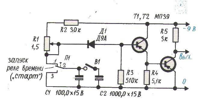
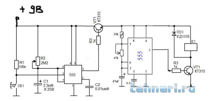
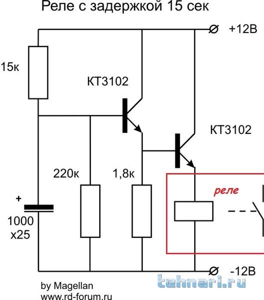
Transistor circuit
Required radio parts:
- Transistor KT 3102 (or KT 315) - 2 pcs.
- Capacitor.
- Resistor with a nominal value of 100 kOhm (R1). You will also need 2 more resistors (R2 and R3), the resistance of which will be selected along with the capacitance, depending on the timer operation time.
- Button.
When the circuit is connected to a power source, the capacitor will begin to charge through resistors R2 and R3 and the emitter of the transistor. The latter will open, so the voltage will drop across the resistance. As a result, the second transistor will open, which will lead to the operation of the electromagnetic relay.
When the capacitance is charged, the current will decrease. This will cause a decrease in the emitter current and a voltage drop across the resistance to a level that will lead to the closing of the transistors and the release of the relay. To start the timer again, a short press of the button will be required, which will cause the capacity to completely discharge.
To increase the time delay, an insulated gate field effect transistor circuit is used.
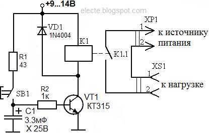
Chip-based
The use of microcircuits will remove the need to discharge the capacitor and select the ratings of radio components to set the required response time.
Necessary electronic components for a 12 volt time relay:
- resistors with a nominal value of 100 Ohm, 100 kOhm, 510 kOhm;
- diode 1N4148;
- capacitance at 4700 uF and 16 V;
- button;
- chip TL 431.
The positive pole of the power supply must be connected to the button, to which one relay contact is connected in parallel. The latter is also connected to a 100 ohm resistor. On the other hand, resi
How an electronic timer works
Unlike the very first clockwork timers, modern time relays are much faster and more efficient.Many of them are based on microcontrollers (MCs) capable of performing millions of operations per second.
This speed is not needed to turn on and off, so the microcontrollers were connected to timers that could count the pulses that occur inside the MK. Thus, the central processor executes its main program, and the timer provides timely actions at certain intervals. Understanding the principle of operation of these devices will be needed even when making a simple do-it-yourself capacitive time relay.
The principle of operation of the time relay:
- After the start command, the timer starts counting from zero.
- Under the influence of each pulse, the content of the counter increases by one and gradually acquires a maximum value.
- Next, the contents of the counter are reset to zero, since it becomes “overflowing”. At this point, the time delay ends.
This simple design allows you to get a maximum shutter speed within 255 microseconds. However, in most devices, seconds, minutes, and even hours are required, which raises the question of how to create the required time intervals.
The way out of this situation is quite simple. When the timer overflows, this event causes the main program to abort. Next, the processor switches to the corresponding subroutine, which combines small excerpts with any period of time that is required at the moment. This interrupt service routine is very short, consisting of no more than a few dozen instructions. At the end of its action, all functions return to the main program, which continues to work from the same place.
The usual repetition of commands does not occur mechanically, but under the guidance of a special command that reserves memory and creates short time delays.


