- Classification and why you need a relay
- Protection
- Scope of devices
- The easiest 12V timer at home
- Scheme and principle of operation of an electromagnetic relay
- Starting the engine "Triangle"
- And yet, what is the actual advantage of this relay?
- Coil shorting
- Electromagnetic relays on the diagrams: windings, contact groups
- How to test an electromagnetic relay
- If you don't have a multimeter
- Checking contacts
- Main characteristics of KU
- Instruments with a mechanical scale
- Weekly timer
Classification and why you need a relay
Since relays are highly reliable switching devices, it is not surprising that they are widely used in various fields of human activity. They are used in industry to automate work processes, as well as in everyday life in a wide variety of appliances, for example, in the usual refrigerators and washing machines.
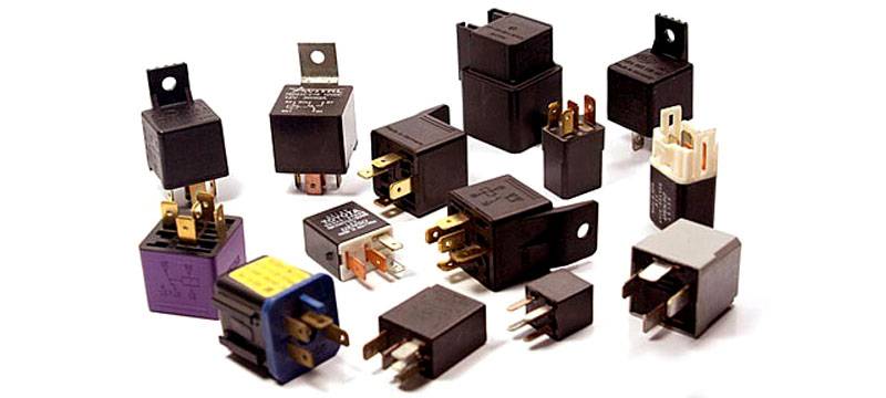 The variety of types of relays is very large and each is designed to perform a specific task.
Relays have a complex classification and are divided into several groups:
By scope:
- management of electrical and electronic systems;
- systems protection;
- systems automation.
According to the principle of action:
- thermal;
- electromagnetic;
- magnetolectic;
- semiconductor;
- induction.
According to the incoming parameter, causing the operation of the KU:
- from current;
- from tension;
- from power;
- from frequency.
According to the principle of influence on the control part of the device:
- contact;
- contactless.
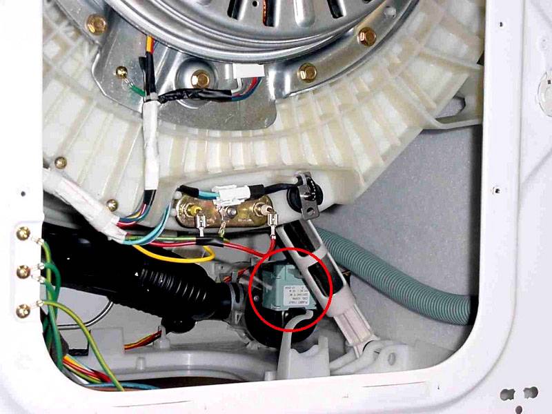 The photo (circled in red) shows where one of the relays is located in the washing machine
Depending on the type and classification, relays are used in household appliances, cars, trains, machine tools, computer technology, etc. However, most often this type of switching device is used to control large currents.
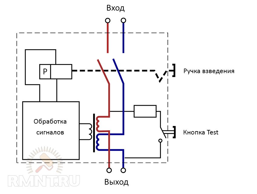
Protection
Most manufacturers recommend fast acting fuses as protection.
This is necessary so that in the event of an overload or short circuit of the load, there is no breakdown of the SSR.
However, since the cost of such fuses is comparable to the cost of the SSR itself,
there is an option to install circuit breakers instead of fuses.
Moreover, manufacturers recommend only circuit breakers with a time-current characteristic of type "B".
To explain the principle of protection, consider the well-known graphs of the time-current characteristics of circuit breakers:
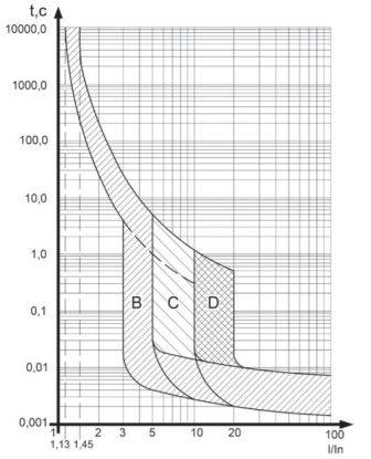
It can be seen from the graph that when circuit breaker current with characteristic "B"
more than 5 times its turn-off time - about 10 ms (half a period of voltage with a frequency of 50 Hz).
From this we can conclude that in order to have a great chance of maintaining the performance of the SSR in the event of a short circuit,
you need to use circuit breakers with characteristic "B".
In this case, it is necessary to calculate the currents of the load and the circuit breaker accordingly, depending on the maximum current of the solid state relay.
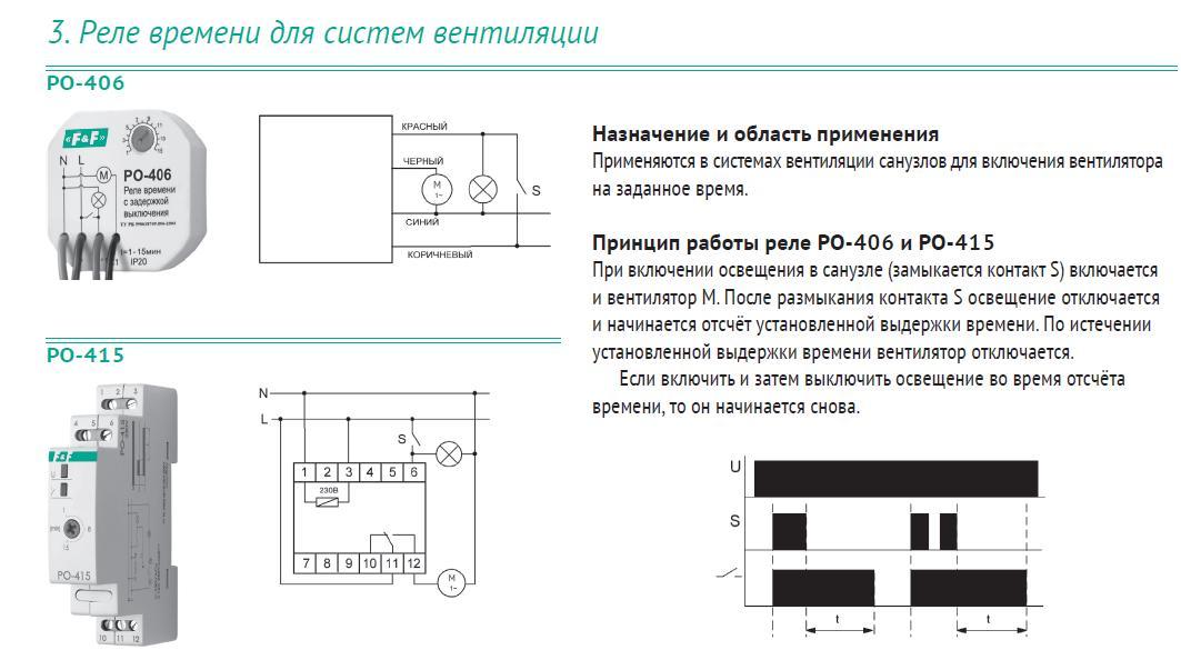
Scope of devices
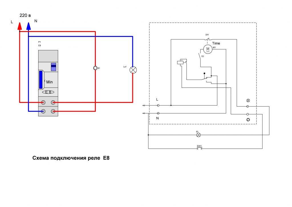
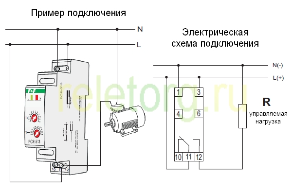
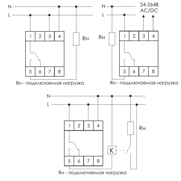
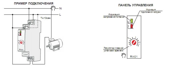
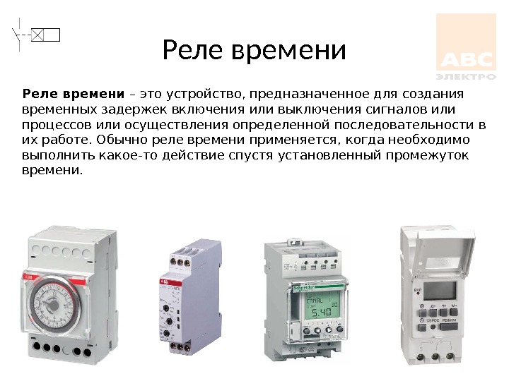
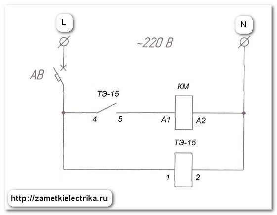
Timers are used in many devices surrounding modern man.Often, in life, it is required to automate the start and stop cycles of various equipment.
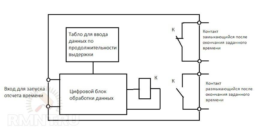
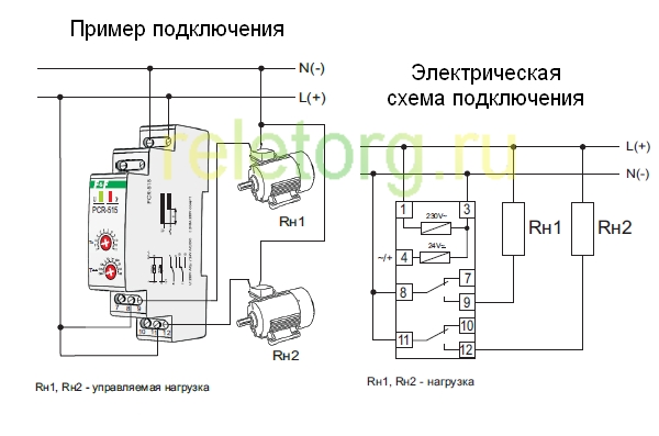
The connection scheme of the time relay is so simple that it allows such an operation controller to be used in a wide range of household and industrial equipment, starting or turning off the equipment after certain periods. Examples of use are washing machines, microwave ovens, machine tools, traffic lights, street lighting, irrigation systems, and home heating controls. Modern time relay
Time relays have been used for so long that even information about the first engineer who introduced such functions into his equipment could not be found. The first mention and attempt to separate work time control systems according to the principle of operation was made in 1958, in the book by V. Bolshov "Electronic Time Relays".
It is significant that even then the need for periodic start-up and shutdown of equipment was taken for granted. The book suggested dividing timers into hourly, air, electronic and electromagnetic ones, depending on the type of functioning mechanism. Time relays used in the USSR
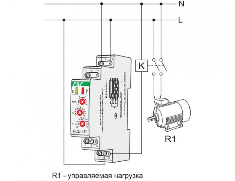
In modern life, timers that turn off and control the power of equipment, and this is another name for such a device, are used everywhere, both to control production processes and consumer electronics.
Time relays are especially important in smart home systems, in which they measure time intervals and control certain processes. The simplest example is automatic light in the entrances of residential buildings. The sensor, when motion is detected, gives a signal to start the timer, which lights up the lighting. If there is no signal from the sensor for a long period, the time relay is activated and the light goes out.One of the schemes for connecting a time relay to the entrance lighting
This is interesting: Shunt release or voltage relay - which is better to choose
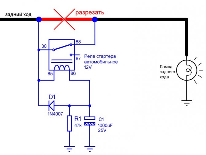
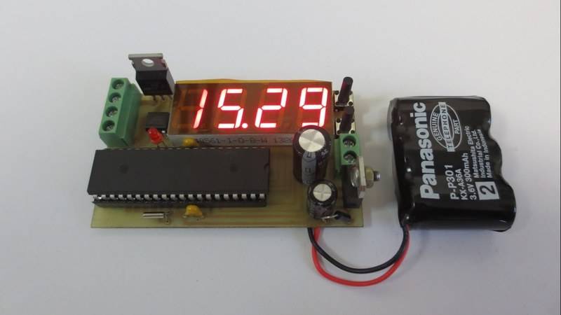
The easiest 12V timer at home
The simplest solution is a 12 volt time relay. Such a relay can be powered from a standard 12v power supply, of which there are a lot of sold in various stores.
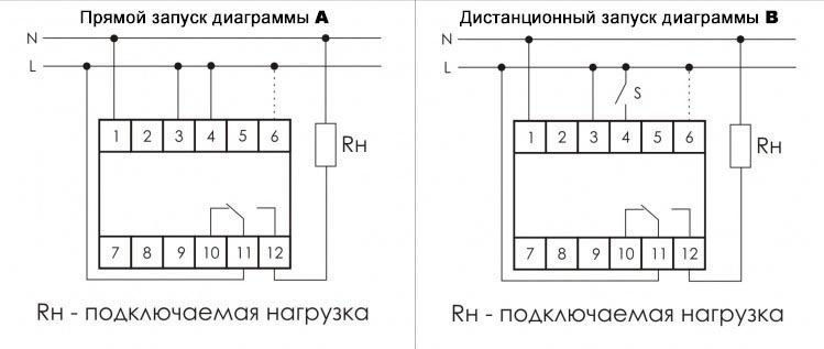
The figure below shows a diagram of a device for turning on and off the lighting network, assembled on one counter of the integral type K561IE16.
Picture. A variant of the 12v relay circuit, when power is applied, it turns on the load for 3 minutes.
This circuit is interesting in that the blinking LED VD1 acts as a clock pulse generator. Its flicker frequency is 1.4 Hz. If the LED of a particular brand cannot be found, then you can use a similar one.
Consider the initial state of operation, at the time of 12v power supply. At the initial moment of time, the capacitor C1 is fully charged through the resistor R2. Log.1 appears on the output under No. 11, making this element zero.
The transistor connected to the output of the integrated counter opens and supplies a voltage of 12V to the relay coil, through the power contacts of which the load switching circuit closes.
The further principle of operation of the circuit operating at a voltage of 12V is to read the pulses coming from the VD1 indicator with a frequency of 1.4 Hz to pin No. 10 of the DD1 counter. With each decrease in the level of the incoming signal, there is, so to speak, an increment in the value of the counting element.
When a 256 pulse arrives (this equals 183 seconds or 3 minutes), a log appears on pin No. 12. 1. Such a signal is a command to close the transistor VT1 and interrupt the load connection circuit through the relay contact system.
At the same time, log.1 from output under No. 12 enters through the VD2 diode to the clock leg C of the DD1 element. This signal blocks the possibility of receiving clock pulses in the future, the timer will no longer work, until the 12V power supply is reset.
The initial parameters for the operation timer are set in different ways of connecting the transistor VT1 and the diode VD3 indicated in the diagram.
By slightly transforming such a device, you can make a circuit that has the opposite principle of operation. The KT814A transistor should be changed to another type - KT815A, the emitter should be connected to the common wire, the collector to the first contact of the relay. The second contact of the relay should be connected to the 12V supply voltage.
Picture. A variant of the 12v relay circuit that turns on the load 3 minutes after power is applied.
Now, after power is applied, the relay will be turned off, and the control pulse opening the relay in the form of log.1 output 12 of the DD1 element will open the transistor and apply a voltage of 12V to the coil. After that, through the power contacts, the load will be connected to the electrical network.
This version of the timer, operating from a voltage of 12V, will keep the load in the off state for a period of 3 minutes, and then connect it.
When making the circuit, do not forget to place a 0.1 uF capacitor, marked C3 on the circuit and with a voltage of 50V, as close as possible to the supply pins of the microcircuit, otherwise the counter will often fail and the relay exposure time will sometimes be less than it should be.
In particular, this is the programming of the exposure time. Using, for example, such a DIP switch as shown in the figure, you can connect one switch contacts to the outputs of the counter DD1, and combine the second contacts together and connect to the connection point of the VD2 and R3 elements.
Thus, with the help of microswitches, you can program the delay time of the relay.
Connecting the connection point of the elements VD2 and R3 to different outputs DD1 will change the exposure time as follows:
| Counter foot number | Counter digit number | holding time |
|---|---|---|
| 7 | 3 | 6 sec |
| 5 | 4 | 11 sec |
| 4 | 5 | 23 sec |
| 6 | 6 | 45 sec |
| 13 | 7 | 1.5 min |
| 12 | 8 | 3 min |
| 14 | 9 | 6 min 6 sec |
| 15 | 10 | 12 min 11 sec |
| 1 | 11 | 24 min 22 sec |
| 2 | 12 | 48 min 46 sec |
| 3 | 13 | 1 hour 37 min 32 sec |
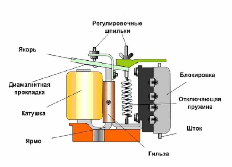
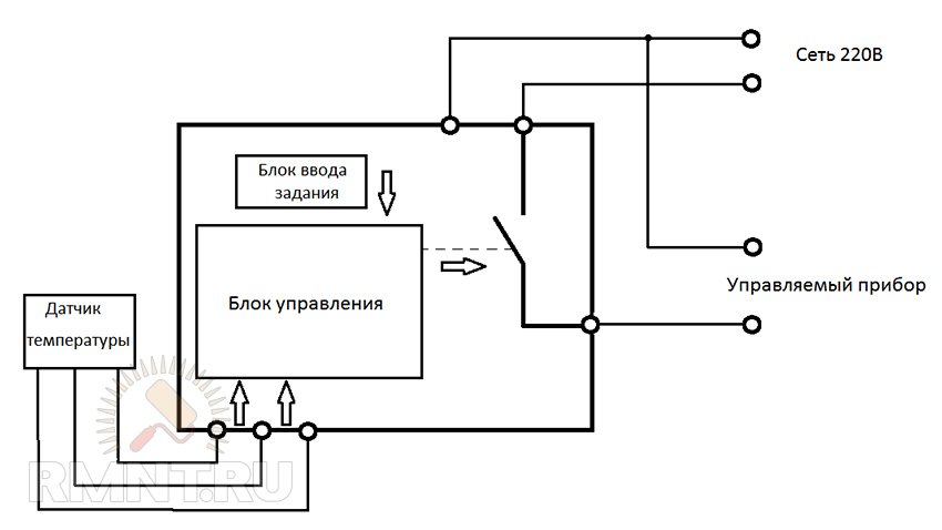
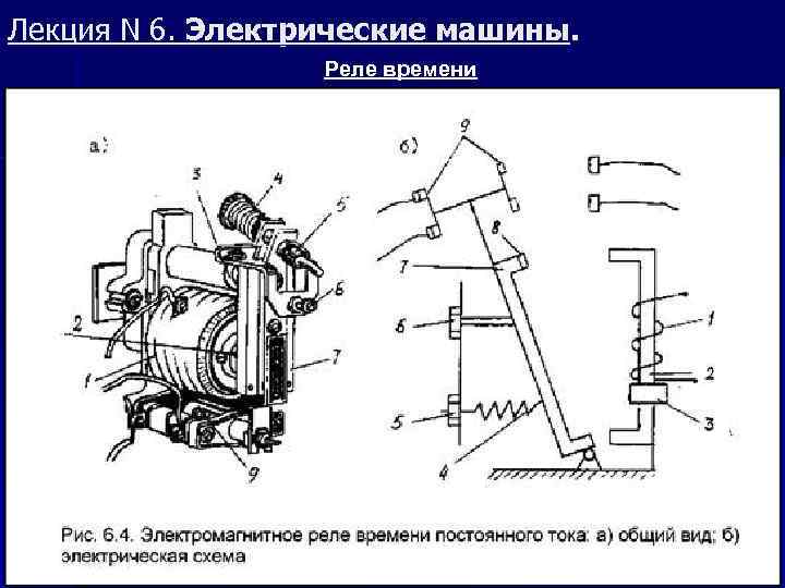
Scheme and principle of operation of an electromagnetic relay
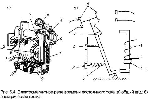
Consider how this mechanism works from the inside.
- The inductor contains a movable steel armature.
- When voltage is applied to the coil, an electromagnetic field is formed around it, which attracts this armature to the coil.
- The frequency and time of voltage supply is regulated electrically or mechanically.
The structure of the device consists of three main elements:
- Perceiving or primary - in fact, this is the winding of the coil. Here the momentum is converted into electromagnetic force.
- Retarding or intermediate - a steel anchor with a return spring and contacts. Here the actuator is brought into working condition.
- Executive - in this part, the contact group has a direct impact on power equipment.
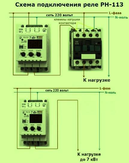
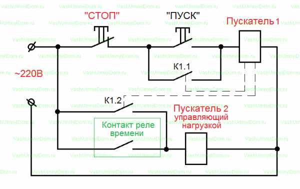
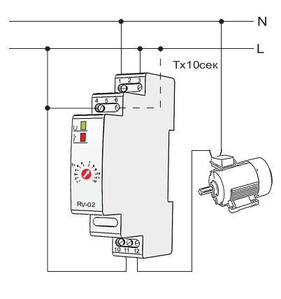
Starting the engine "Triangle"
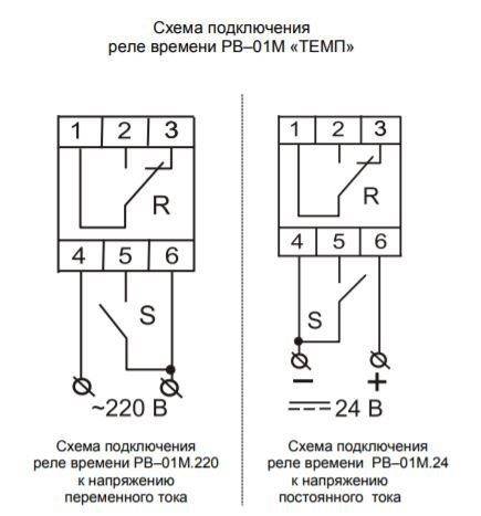
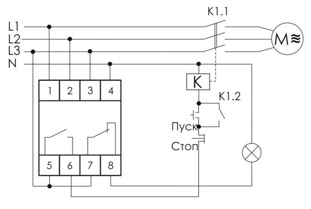
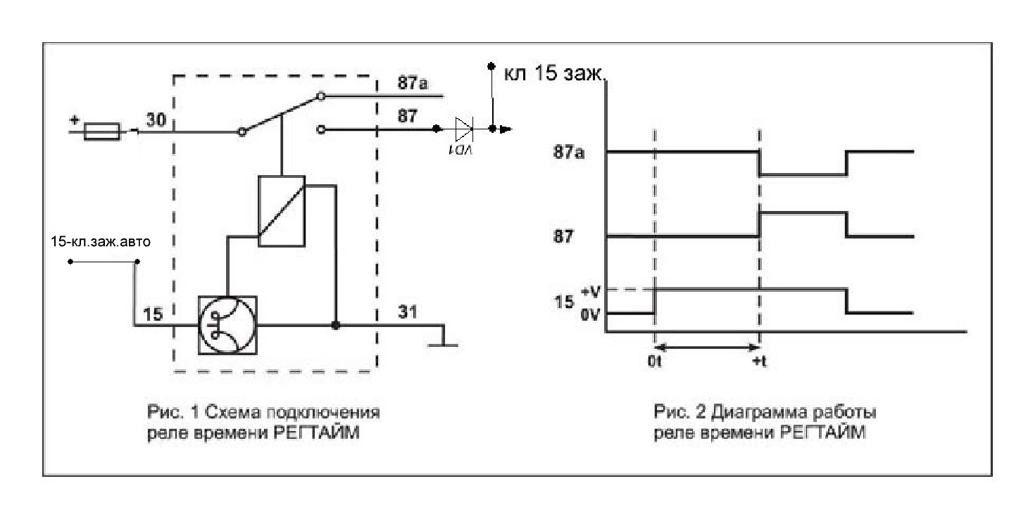
After some time (installed on the front panel of the relay), the time relay KT1 switches its contact from 17-18 to contact 17-28, thereby turning off the KM3 contactor in the "Star" mode.
After switching the executive contact of the time relay KT1, the contactor KM2 is switched on. Power contacts KM2 apply voltage to the end of the winding U2-V2-W2, the "Triangle" mode is activated.
Auxiliary contact 53-54 on the KM2 contactor supplies voltage to the HL2 bulb (Engine start in "Delta" mode is on)
Phew, perhaps this is all according to the scheme))). So this actually works, and to turn it all off, you need to press the SB1 button.
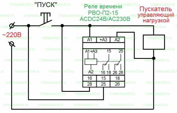
And yet, what is the actual advantage of this relay?
I'll try to say it in my own words: for engines with high power, the starting current at startup can exceed the operating current by 5-7 times.
For this simple reason, time relays such as RT-SD are used to start the engine according to the Star-Delta scheme.
The RT-SD time relay is, so to speak, “the main thing is not to make a mistake”, an alternative to soft starters. Because soft starters are much more expensive than time relays, which is why they are used quite often today.
Okay, dear friends! I look forward to your comments on the topic and do not forget to click on the buttons to share this topic with your friends. On this I conclude this article, but I do not close this topic completely, I have one more thought in reserve.
Coil shorting
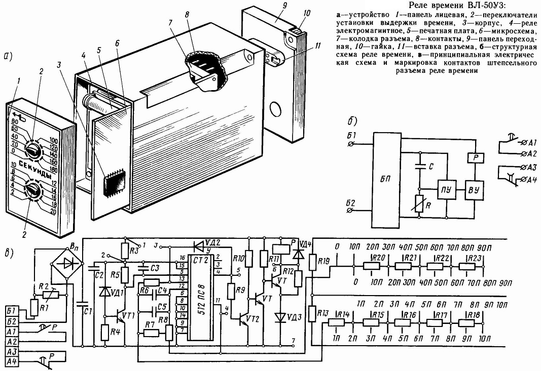
Figure 2. Scheme for obtaining the time delay for electromagnetic time relays with various options for turning on the pull-in coil.
When the RV relay is turned on, the armature is attracted very quickly (the relay charge time is 0.8 sec). When disconnected, a time delay is created, while the relay can be turned off both by breaking the coil circuit and by shorting it (Fig. 2a).The time delay when shorting the coil is obtained for the following reason. For the armature to fall off (and, consequently, the relay contacts to operate), it is necessary that the flux in the magnetic system disappear or decrease to a certain value, which happens when the relay coil is powered off, i.e., when it is turned off.
If, however, the relay coil is shunted (for example, by parallel connection of any contacts of another intermediate relay RP), then due to self-induction in the circuit formed by the relay coil and the RP contact, current is maintained for some time. Consequently, the magnetic flux and the force of attraction of the armature to the core will also fade gradually. Resistance R in the coil circuit must be provided to prevent a short circuit (if there are no other consumers in this circuit).
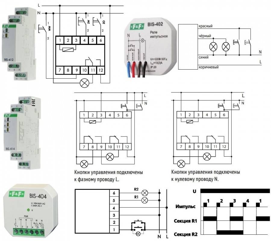
Electromagnetic relays on the diagrams: windings, contact groups
The peculiarity of the relay is that it consists of two parts - winding and contacts. Winding and contacts have a different designation. The winding graphically looks like a rectangle, the contacts of different ones each have their own designation. It reflects their name/purposes, so there are usually no problems with identification.
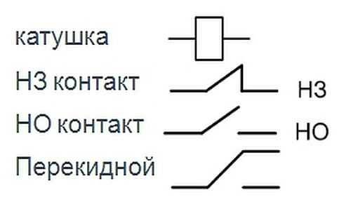
Types of contacts of electromagnetic relays and their designation on the diagrams
Sometimes a type designation is placed next to the graphic image - NC (normally closed) or NO (normally open). But more often they prescribe belonging to the relay and the number of the contact group, and the type of contact is clear from the graphic image.
In general, you need to look for relay contacts throughout the circuit. After all, physically it is in one place, and its different contacts are part of different circuits. This is shown in the diagrams. Winding in one place - in the power supply circuit.Contacts are scattered in different places - in the circuits in which they work.
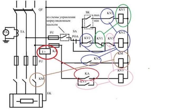
Example of a circuit on electromagnetic relays: the contacts are in the corresponding circuits (see color coding)
For an example, look at the diagram with the relay. Relays KA, KV1 and KM have one contact group, KV3 - two, KV2 - three. But three is far from the limit. Contact groups in each relay can be ten or twelve or more. And the diagram is simple. And if it occupies a couple of sheets of A2 format and there are a lot of elements in it ...
How to test an electromagnetic relay
The performance of the electromagnetic relay depends on the coil. Therefore, first of all, we check the winding. They call her a multimeter. The winding resistance can be either 20-40 ohms or several kilohms. When measuring, simply select the appropriate range. If there is data on what resistance value should be, we compare. Otherwise, we are content with the fact that there is no short circuit or open circuit (resistance tends to infinity).
You can check the electromagnetic relay using a tester / multimeter
The second point is whether the contacts switch or not and how well the contact pads fit. Checking this is a little more difficult. A power supply can be connected to the output of one of the contacts. For example, a simple battery. When the relay is triggered, the potential must appear on the other contact or disappear. This depends on the type of contact group being tested. You can also control the presence of power using a multimeter, but it will need to be switched to the appropriate mode (voltage control is easier).
If you don't have a multimeter
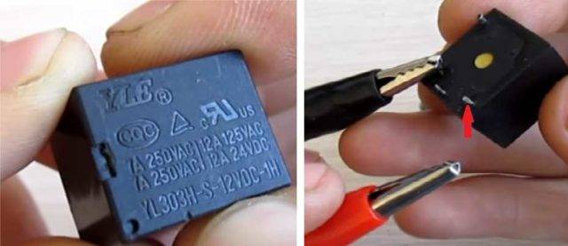
A multimeter is not always at hand, but batteries are almost always available. Let's look at an example. There is some kind of relay in a sealed case.If you know or found its type, you can see the characteristics by name. If the data is not found or there is no name of the relay, we look at the case. Usually all important information is indicated here. Supply voltage and switched currents/voltages are required.
Checking the winding of the electromagnetic relay
In this case, we have a relay that operates from 12 V DC. Well, if there is such a power source, then we use it. If not, we collect several batteries (in series, that is, one by one) in order to get the required voltage in total.
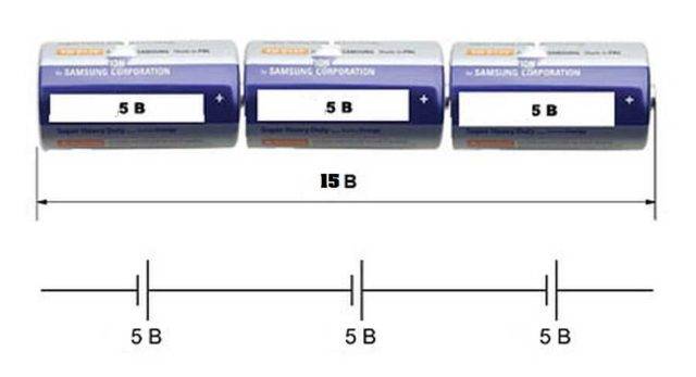
When batteries are connected in series, their voltage is summed up
Having received a power source of the desired rating, we connect it to the terminals of the coil. How to determine where the coil leads? Usually they are signed. In any case, there are “+” and “-” designations for connecting DC power supplies and signs for a variable type such as “≈”. We supply power to the corresponding contacts. What's happening? If the relay coil is working, a click is heard - this is an anchor pulled. When the voltage is removed, it is heard again.
Checking contacts
But clicks are one thing. This means that the coil is working, but you still need to check the contacts. Perhaps they are oxidized, the circuit closes, but the voltage drops sharply. Maybe they are worn out and the contact is bad, maybe, on the contrary, they boil and do not open. In general, for a full check of the electromagnetic relay, it is also necessary to check the performance of the contact groups.
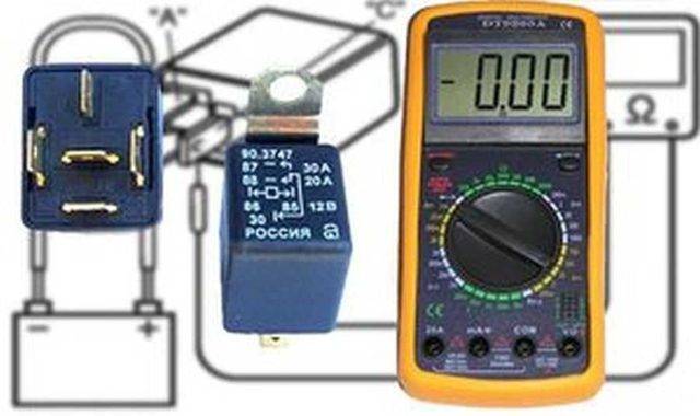
The easiest way to explain is with the example of a relay with one group. They are usually found in cars. Motorists call them by the number of pins: 4 pin or 5 pin.In both cases there is only one group. It's just that a four-contact relay contains a normally closed or normally open contact, and a five-contact relay contains a switching group (changeover contacts).
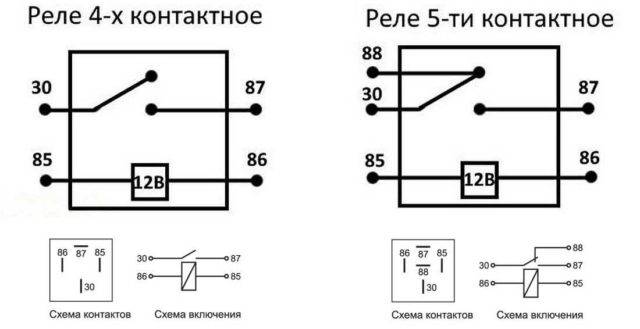
Electromagnetic relay 4 and 5 pin: pin arrangement, wiring diagram
As you can see, power is supplied in any case to the conclusions that are signed 85 and 86. And the load is connected to the rest. To test a 4-pin relay, you can assemble a simple bundle of a small light bulb and a battery of the desired rating. Screw the ends of this bundle to the terminals of the contacts. In a 4-pin relay, these are pins 30 and 87. What happens? If the contact is closed (normally open), when the relay is activated, the lamp should light up. If the group is open (normally closed) should go out.
In the case of a 5-pin relay, the circuit will be a little more complicated. Here you will need two bundles of light bulbs and batteries. Use lamps of different sizes, colors, or separate them in some way. If there is no power on the coil, you should have one light on. When the relay is activated, it goes out, another one lights up.
Main characteristics of KU
The main characteristics that you should pay attention to when choosing this type of switching device include:
- sensitivity - operation from a current of a certain strength supplied to the winding, sufficient to turn on the device;
- electromagnet winding resistance;
- operation voltage (current) - the minimum allowable value sufficient to switch contacts;
- release voltage (current) - the value of the parameter at which the CU is turned off;
- the time of attraction and release of the anchor;
- operating frequency with operating load on the contacts.
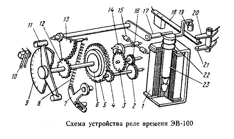
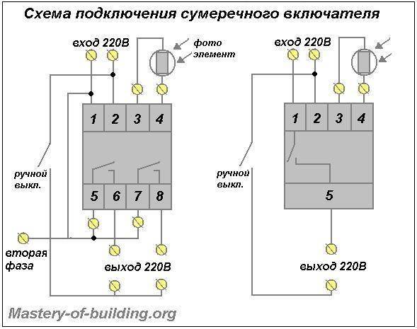
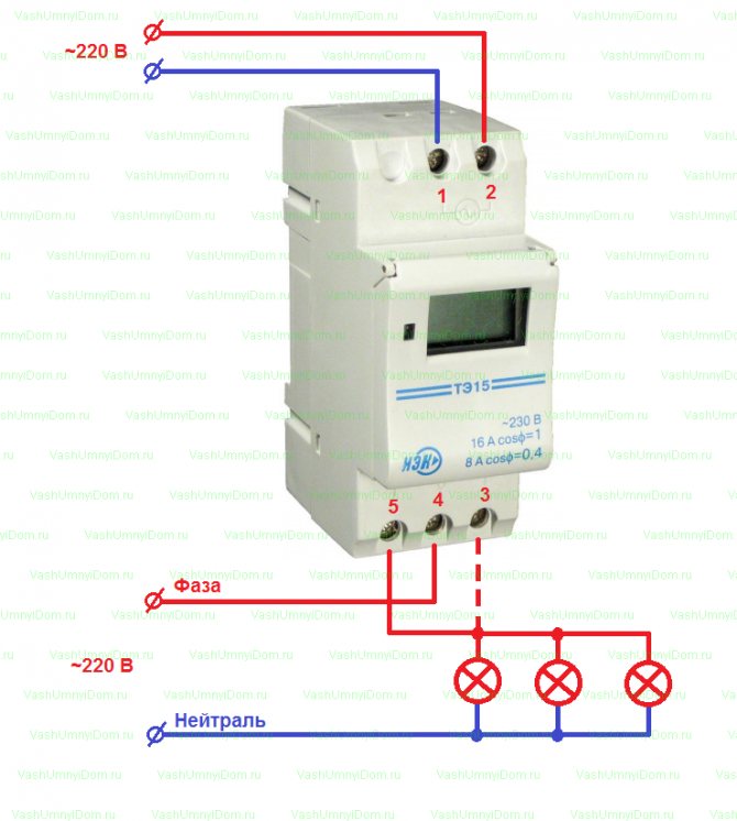
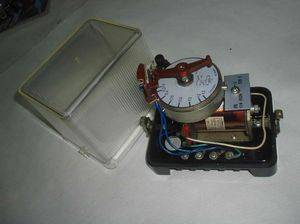
Instruments with a mechanical scale
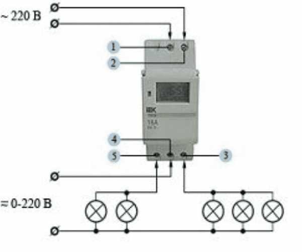
One of the devices that has a mechanical scale is a household timer. It works from a regular outlet. Such a device allows you to control home appliances in a certain time range. It has a "socket" relay, which is limited to a daily cycle of operation.
To use the daily timer, you need to configure it:
- Raise all elements that are located on the disk circumference.
- Omit all elements that are responsible for setting the time.
- Scrolling the disk, set it to the current time interval.
For example, if the elements are lowered on the scale marked with the numbers 9 and 14, then the load will be activated at 9 am and will be turned off at 14:00. Up to 48 activations of the device can be created per day.
To do this, you need to activate the button, which is located on the side of the case. If you run it, the timer will turn on in urgent mode, even if it was turned on.
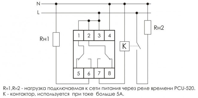
Weekly timer
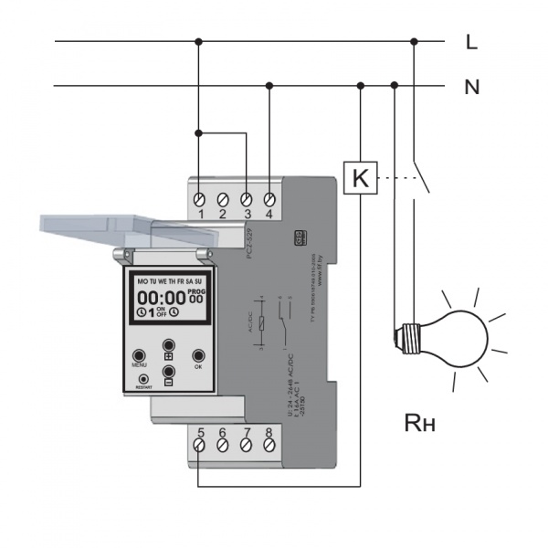
The electronic on-off timer in automatic mode is used in various fields. The “weekly” relay switches within a pre-set weekly cycle. The device allows:
- Provide switching functions in lighting systems.
- Enable/disable technological equipment.
- Start / disable security systems.
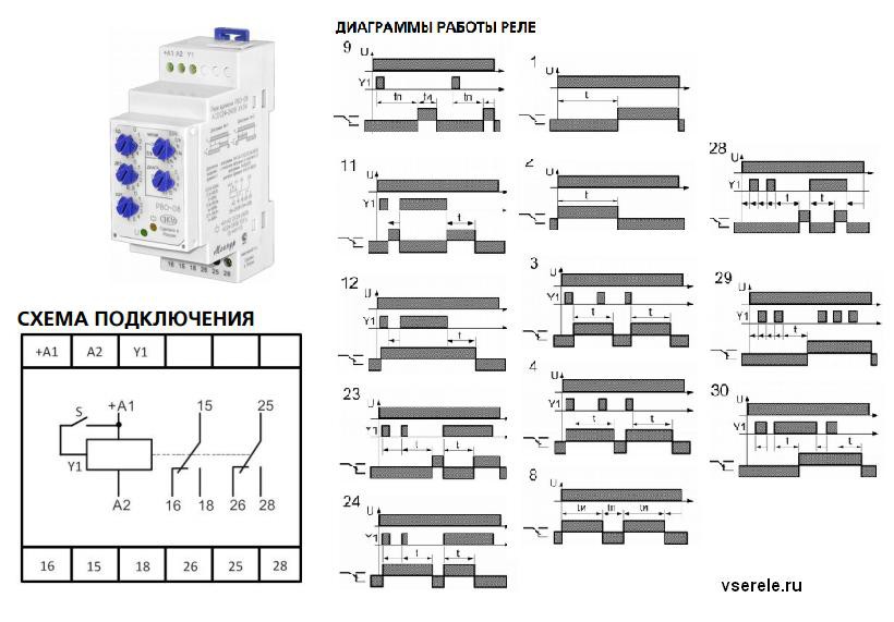
The dimensions of the device are small, the design provides function keys. Using them, you can easily program the device. In addition, there is a liquid crystal display that displays information.
 The control mode can be activated by pressing and holding the "P" button. The settings are reset with the "Reset" button. During programming, you can set the date, the limit is a weekly period.The time relay can operate in manual or automatic mode. Modern industrial automation, as well as various household modules, are most often equipped with devices that can be configured using potentiometers.
The front of the panel assumes the presence of one or more potentiometer rods. They can be adjusted with a screwdriver blade and set to the desired position. There is a marked scale around the stem. Such devices are widely used in the control of ventilation and heating systems.


