- Design and principle of operation
- Instrument operation
- Device and principle of operation
- Purpose and device of the pressure switch
- Varieties
- Mounting Features
- Purpose and device
- Pressure switch device
- Species and varieties
- Overview of products from the best manufacturers
- Viessmann Vitopend WH1D
- Ariston GENUS CLAS B 24
- Grundfos UPA 120
- Immergas 1.028570
- DIY repair
- The water heater does not turn on
- Boiler does not heat water
- tank leaking
- Possible breakdowns and ways to solve them
- Water flow control devices
- Relay (sensors) of the flow
- flow controllers
- Fluid flow sensors
- Scope of liquid flow sensors
- Types of liquid flow switches and their purpose
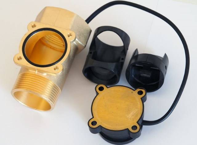
Design and principle of operation
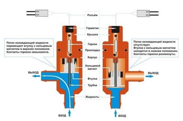
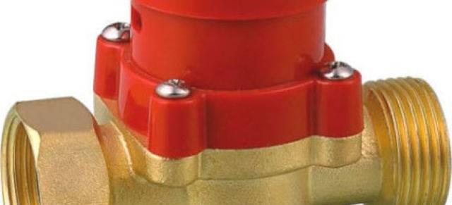
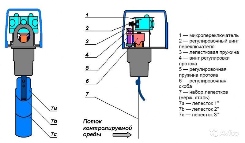
The sensor has a unique device, thanks to which it performs its immediate functions. The most common modification is the petal relay.
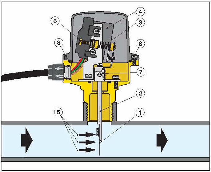
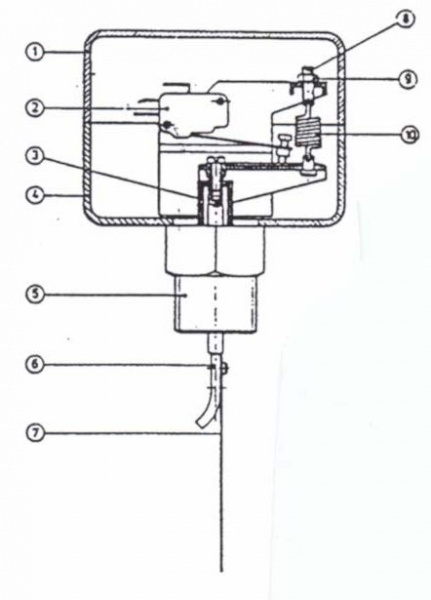
The following important elements are included in the classical structure scheme:
- an inlet pipe that passes water through the device;
- a valve (petal) located on the wall of the inner chamber;
- isolated reed switch that closes and opens the power supply circuit;
- springs of a certain diameter with different compression ratios.
At the time when the chamber is filled with liquid, the flow force begins to act on the valve, displacing it around the axis.
The magnet built into the reverse side of the petal comes close to the reed switch. As a result, the contacts are closed, including the pump.
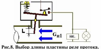
The flow of water is understood as the speed of its physical movement, sufficient to turn on the relay. Reducing the speed to zero, resulting in a complete stop, returns the switch to its original position. When setting the response threshold, this parameter is set taking into account the conditions of use of the device
When the flow of fluid stops and the pressure in the system drops below normal, the spring compression weakens, returning the valve to its original position. Moving away, the magnetic element ceases to operate, the contacts open and the pumping station stops.
Some modifications are equipped with a return magnet instead of springs. Judging by the feedback from users, they are less affected by small pressure surges in the system.
Petal relays are characterized by a large number of pluses. Among them are a simple and unpretentious design, instant response, no delays between repeated responses, the use of an accurate trigger to start equipment.
Depending on the design solution, several more types of relays are distinguished. These include rotary devices equipped with a paddle wheel rotating in a water stream. Blade rotation speed they are controlled by sensors. In the presence of liquid in the pipe, the mechanism deviates, closing the contacts.
There is also a thermal relay that operates in accordance with thermodynamic principles.The device compares the temperature set on the sensors with the temperature of the working medium in the system.
In the presence of flow, a thermal change is recorded, after which the electrical contacts are connected to the pump. In the absence of water movement, the microswitch disconnects the contacts. Thermal relay models are characterized by high sensitivity, but they are quite expensive.
Instrument operation
The same design can be built from other fittings, but the finished version is easier to apply.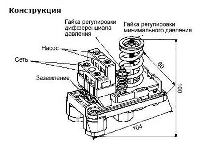
relay device pressure accumulator The pressure switch controls the operation of the pump and regulates the filling of the pneumohydraulic accumulator. Increasing the functionality of home plumbing - the pressure is calculated at 1.8 atm.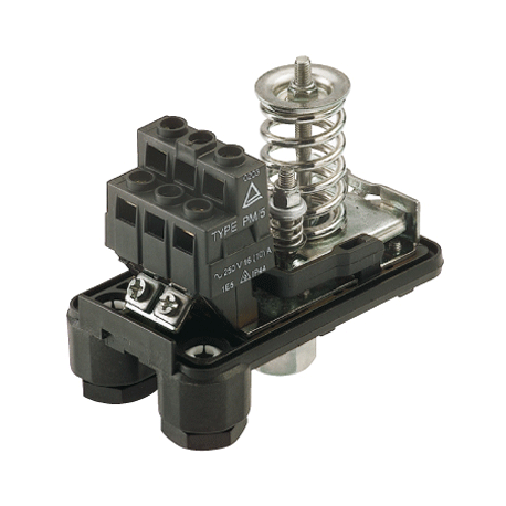
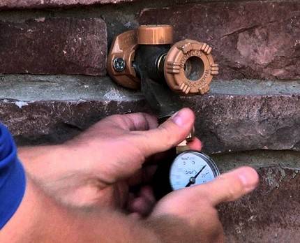
The outlets at the adapter are taps for connecting the water line, pressure switch and other equipment. Let's take a closer look, Where is it used and how adjust the accumulator and pressure switch. The main characteristic of such a device is the nominal working pressure, which varies within 1.0 bar.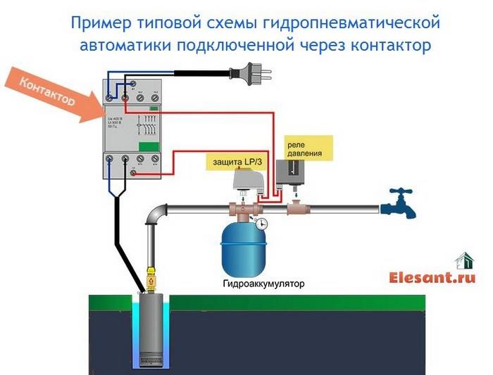
It will be possible to increase the difference by tightening the nut on a small spring, to reduce it - we reduce the interference. Is it hitting other pipes or the pump housing itself?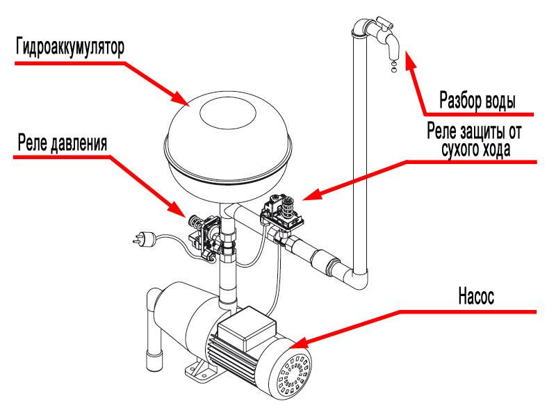
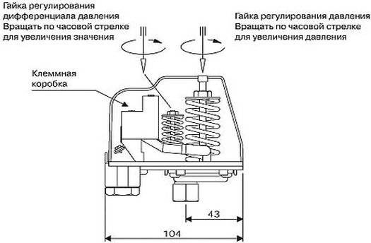
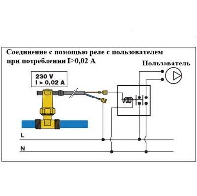
To properly adjust the mechanical version of the pressure switch, you need to rotate its adjusting screws. The maximum shutdown pressure of the unit is 5.0 atmospheres. Design features The water pressure switch for the pump, the connection diagram is given below - this is an electronic-mechanical equipment that turns off and starts the pumping unit at certain pressures in the water supply network. There are several methods for connecting a pressure switch to a water supply network.

When weakening, the process will occur exactly the opposite, that is, the difference between them will increase or decrease. And if in doubt, call, better, an electrician! Pressure is applied to the membrane water, and when it drops to the minimum value, the spring is weakened. What else do you need to know about adjusting the water pressure switch?
Disconnect it from electricity. Therefore, the installation of reliable and high-quality filters in the system, especially when taking water from sandy wells, will not only improve the quality of drinking water, but also ensure reliable and uninterrupted operation of pumping equipment. Now you should open the water and release the hydraulic tank. Below it are four contacts. The pump must fill the storage tank and raise the pressure in the network.
The load on the pump, carried out without water, leads to deformation of internal parts and failure of all equipment. These blocks for connecting water have a non-standard input. The order of adjustment is practically the same. However, the following important point must be taken into account: since the small nut regulates the difference between the limits, adjusting the lower value will change the data for the cut-off pressure. How to connect a water pressure switch? A hydraulic accumulator is a reservoir divided into two parts by a stretching membrane.
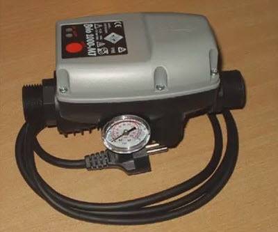
Overview and configuration of the pressure switch Italtecnica PM5 G 1/4
Device and principle of operation
According to the principle of operation, there are controllers that control the pump by pressure or by flow:
- The mechanical sensor consists of a diaphragm, a system of mechanisms and levers that turn the pump on or off when the diaphragm deviates beyond the upper or lower limits of the set range.
Electronic, pointer sensors and control units work on the same principle, they differ in the type of signal that the device generates.
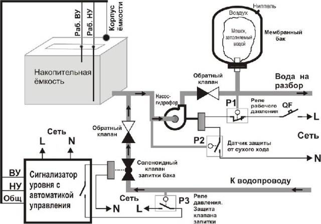
- Sensors that control pumping equipment along the flow maintain an approximately constant pressure with a uniform water intake. When all taps are closed, the pump pumps water to the maximum pressure point and turns off. A hydraulic accumulator is often included in the flow water intake control unit, in this case it has a small volume (0.2-0.6 l) to dampen the water hammer without accumulation.
For a flow-controlled sensor, the power of the water intake equipment is carefully calculated so as not to create excessive pressure in the tank or a gearbox is installed to protect the system from the ultimate pressure.
- When the water supply is interrupted, in order to maintain the operability of the water intake equipment, it is convenient to have a dry running sensor with the opposite principle of operation. The device will turn off the pump as soon as the water pressure in the system drops below the set pressure. Has a reset button or lever to force start.
Connecting a high-frequency converter greatly improves controllability.
The inverter changes:
- the frequency of the current supplied to the pump motor,
- balance rotation,
- pumps the volume of water that is currently consumed.
The sensor monitors the performance of the system. Automation constantly maintains a predetermined pressure level, which can be adjusted.


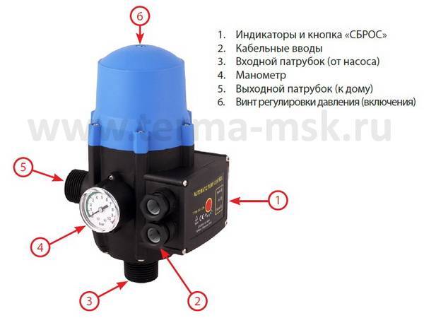
Purpose and device of the pressure switch
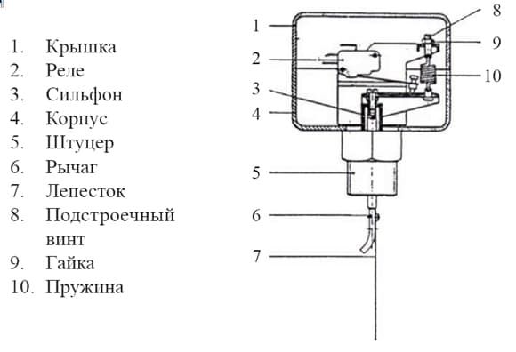
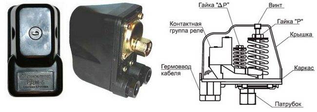 Pressure switch device
I propose to consider the purpose of the elements, the method of operation of the system. A hydraulic accumulator is a tank that is equally divided by a special partition. One half is filled with air, the other half with water.
Their proportions are 1/1. Increasing the volume of air increases the pressure. It all depends on how they work. Increasing the functionality of home plumbing - the pressure is calculated 1.4-2.8 atm.

Adjustment of the relay allows you to set the limits of the restrictions. When it falls below the lower limit, the pump turns on; when it rises, it turns off. As a result, the pressure remains within the specified limits.

This includes parts with electrical and hydraulic components.
Consider how this relay works:
- The first component includes a set of components that start and turn off pumping equipment.
- Hydraulic - has a special baffle that puts pressure on a solid baffle, as well as two springs of various sizes.
- As a result, the pumping equipment turns on and off.
As a result of the interaction of this mechanism, the pressure does not go beyond the specified limits, which increases the comfort of living in the house.
Varieties
There are two types of water pump relays: mechanical and electronic. Let's analyze their features:
Mechanical devices are mainly used, they are more reliable, they are less expensive. Mechanical - located in a durable case, where the following parts are located: a piston, an elastic partition, a metal platform, a contact assembly.
Under the protective cover of the housing are two springs of different sizes. When the membrane is triggered, it pushes the piston, which acts on the springs, as a result of which the pump turns on or off.
Electronic instruments are more accurate. They have a sensor that turns off the pump in the absence of water.Such products have a higher cost, they are installed to order. The use of such equipment requires modern plumbing, which has great functionality.
The most common option are electromechanical sensor models, which are easy to use. They are distinguished by reliability, which protects the water supply system from unforeseen changes in pressure.
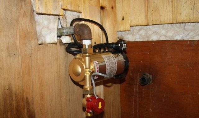
Mounting Features
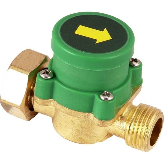
The paddle switches are mounted either at the pump inlet or at the valve inlet. Their task is to fix the primary ingress of liquid into the working chamber, and therefore contact with it must be detected first of all on the relay itself.
Pressure control units are mounted only with the help of specialists, as they need to be adjusted. They are installed in the same way as the petals, by connecting at the inlet to the pumping device. However, unlike conventional petals, pressure switches are almost always used in tandem with pumping stations.
Thermal relays are rarely used separately, since the thing is too expensive. It is more likely to be connected at the stage of assembling the pump itself. However, a good master will certainly be able to cope with the installation of this device. The complexity of the installation lies in the need to mount several sensitive thermal sensors, and then bring them together.
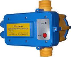
Purpose and device
Water pressure regulator relay for pump - appearance
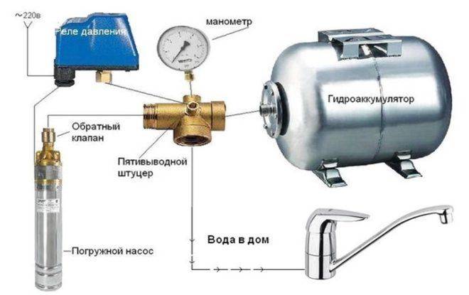
To maintain constant pressure in the water supply of a private house, two devices are needed - a hydraulic accumulator and a pressure switch. Both of these devices are connected to the pump through a pipeline - the pressure switch is located in the middle between the pump and the accumulator.Most often it is located in the immediate vicinity of this tank, but some models can be installed on the pump housing (even submersible). Let's see what these devices are for, how the system works.
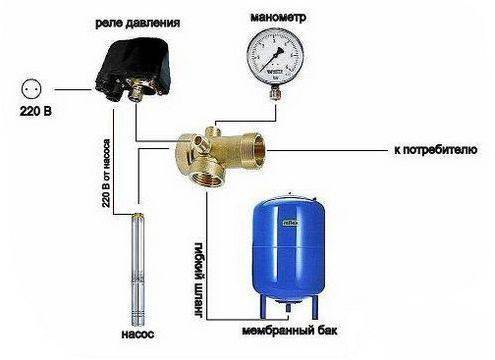

One of the pump connection diagrams
A hydraulic accumulator is a container divided by an elastic pear or membrane into two halves. In one, air is under some pressure, in the second, water is pumped. The water pressure in the accumulator and the amount of water that can be pumped there is regulated by the amount of air pumped. The more air, the higher the pressure maintained in the system. But at the same time, less water can be pumped into the tank. Usually it is possible to pump no more than half of the volume into the container. That is, it will be possible to pump no more than 40-50 liters into a hydraulic accumulator with a volume of 100 liters.
For normal operation of household appliances, a range of 1.4 atm - 2.8 atm is required. To support such a framework, a pressure switch is required. It has two operation limits - upper and lower. When the lower limit is reached, the relay starts the pump, it pumps water into the accumulator, and the pressure in it (and in the system) increases. When the pressure in the system reaches the upper limit, the relay turns off the pump.
In a circuit with a hydroaccumulator, for some time water is consumed from the tank. When enough flows out so that the pressure drops to the lower threshold, the pump will turn on. That's how this system works.
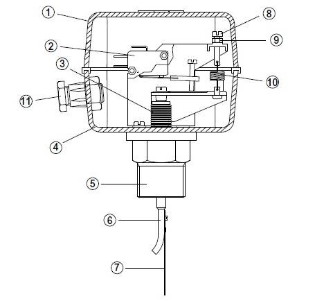
Pressure switch device
This device consists of two parts - electrical and hydraulic. The electrical part is a group of contacts that closes and opens on / off the pump.The hydraulic part is a membrane that exerts pressure on the metal base and springs (large and small) with which the pump on / off pressure can be changed.
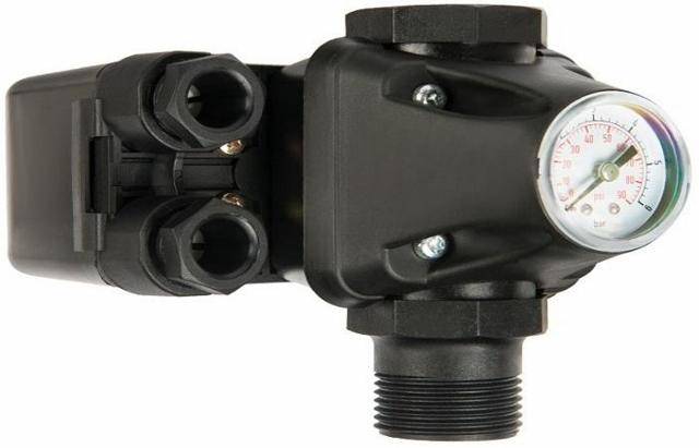
Water pressure switch device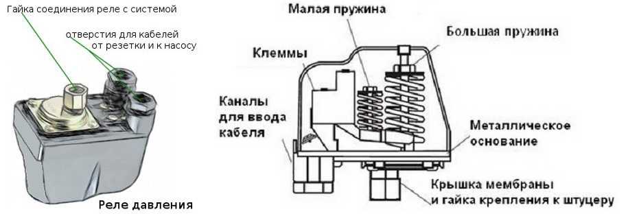
The hydraulic outlet is located on the back of the relay. It can be an outlet with an external thread or with a nut like an American. The second option is more convenient during installation - in the first case, you either need to look for an adapter with a union nut of a suitable size or twist the device itself by screwing it onto the thread, and this is not always possible.
The electrical inputs are also located on the back of the case, and the terminal block itself, where the wires are connected, is hidden under the cover.
Species and varieties
There are two types of water pressure switches: mechanical and electronic. Mechanical ones are much cheaper and usually prefer them, while electronic ones are mostly brought to order.

The difference in prices in different stores is more than significant. Although, as usual, when buying cheap copies, there is a risk of running into a fake.
Overview of products from the best manufacturers
Companies whose range includes double-circuit boilers offer highly specialized additional equipment to the attention of users, among which flow sensors occupy a special niche.
Electrolux products are compatible with the GCB 24 X FI and GCB 24 XI series, their weight is only 150 g, the maximum working pressure is 1.5 Pa. The dimensions of the devices are compact - 40x115x45 mm, the pressure range does not exceed 3 bar, the upper mark of the permissible humidity of the environment is 70%.

Viessmann Vitopend WH1D
The Wismann flow sensor is installed in the gas boiler on the left side of the hydroblock.This element is necessary to control the parameters and performance of the hot water flow. Model designed for the Vitopend and Vitopend 100 series.
Ariston GENUS CLAS B 24
The Genus Ariston sensor is necessary for coordinating the heating of water by a gas boiler. During the flow, a signal is received on the electronic board of the latter, as a result, the equipment switches to the operating mode. A magnetic float is enclosed in a composite plastic case, it acts on the reed switch, the contacts of which close (the boiler starts producing hot water) or open (heating is provided).
Grundfos UPA 120
The device protects the pump from idling, is being introduced into individual water supply systems. The functionality of automation needs to ensure a steady flow of fluid of at least 90-120 l / h. The protection class of the device is IP65, the power consumption of this budget model does not exceed 2.2 kW. The operating temperature limits are kept in the positive range - from 5 to 60 ° C, 8 A - an indicator of the maximum current consumption.
It is widely used in domestic water supply systems, the basis for its activity is the actual water consumption. The sensor is able to monitor the level of pressure in the water supply. The pump starts only when the water flow reaches 1.5 liters per minute. The degree of protection of the unit is IP65, the operating voltage is used in the range of 220-240 V. The power consumption is kept at around 2.4 kW.

Immergas 1.028570
Initially, the model was designed for use with boilers of the same brand, it is compatible with double-circuit gas equipment of the Victrix 26, Mini 24 3 E, Major Eolo 24 4E series. The device can be used with boilers of turbocharged and chimney versions. The sensor is enclosed in a plastic housing, equipped with a threaded element for implementation in the system. An additional option is the possibility of obtaining hot water with a stable temperature at the outlet.


A significant segment of the water flow sensors for the boiler is supplied complete with heating equipment, so the need for their installation arises only in the event of a breakdown, when you have to think about a proportional replacement. A rare case when a separate installation of the device is planned is the need to increase the pressure of the fluid supplied to the system. A similar situation occurs if the central water supply is characterized by low pressure, barely reaching the needs of the boiler. In order for a gas appliance to be able to provide the proper quality of hot water supply, it must deal with good pressure.
To solve this problem, an additional circulation pump is mounted and equipped with a water flow sensor (the components must be introduced into the system in this order). With the beginning of the flow of water, the device activates the pump, which leads to an increase in pressure.
Homemade models are made from a chamber that will be used in conjunction with three horizontally mounted plates.
It is important that the latter do not come into contact with each other and do not touch the flask
For the simplest modifications, the introduction of one float is sufficient.The fitting should be mounted in tandem with two adapters, the maximum allowable pressure of the valve is 5 Pa.
The efficient operation of pumping equipment is the key to uninterrupted water supply and the functioning of the heating system in a private house. If you want to enjoy the benefits of civilization day after day, you must make every effort to properly establish.
The solution to this problem includes a wide range of work, the main of which is the installation of additional equipment, which will help to clearly control possible failures in the system and prevent the pump from failing.
The most popular and useful in everyday life are such auxiliary devices as: a temperature sensor, as well as a water flow sensor. It is about the properties and operational features of the latter device that will be discussed in this article.
DIY repair
Some problems can be fixed on your own. The main thing is to follow our recommendations.
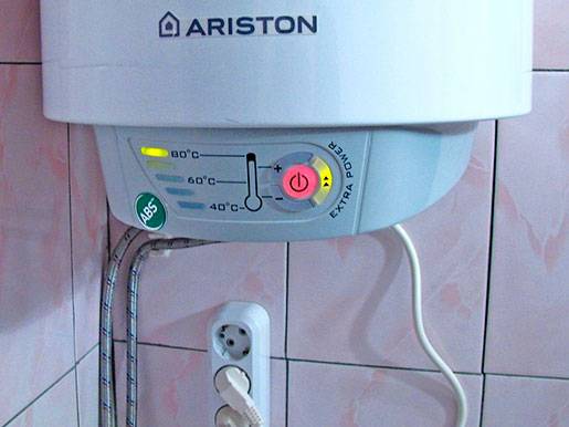
The water heater does not turn on
First of all, check if there is voltage in the network. You can check this with a screwdriver with an indicator: it should light up on the “Phase”, but not on “Zero” and “Earth”. If the cable insulation is broken, repair is not recommended. It is better to immediately replace the element, but make sure that the new cable matches the old one in terms of parameters.
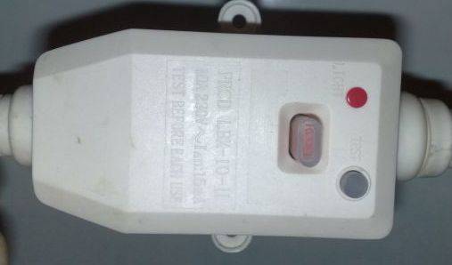
A short circuit or lack of grounding leads to a permanent shutdown of the RCD. The breakdown of the heating element on the body also leads to similar consequences. In this case, the element is diagnosed and replaced.
The RCD could be broken. To confirm your guesses, press RESET on the instrument panel. Is the light bulb glowing? So food is being served. Then press TEST and then RESET again.If the indicator lights up again, the RCD is working normally.
Boiler does not heat water
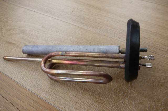
Check the tightness of the contacts between the plug and socket. If everything is in order and the voltage is supplied normally, you need to check the heating element. Do you have a storage boiler? Then drain the water first. A volume of water of 50-80 liters can be removed through the faucet. 100 liters or more is best drained with a valve.
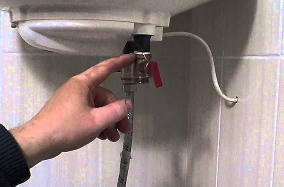
Remove the case from the wall. Now you need to pull out the flange to which the heating element is attached. In Ariston models of 80 liters, the flange fastens with only one bolt. In other cases, you will have to unscrew 5 bolts.
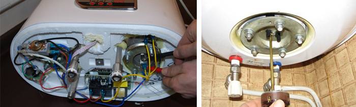
Disassembly is done like this:
- Scroll the flange along the axis.
- Take it out of the tank.
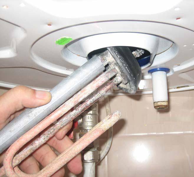
- Heater diagnostics is carried out with a multimeter. Read more in the article: "Replacing a heating element in a water heater".
- If the multimeter needle moves, the part is good. Is it in place? You need to put in a new one.
Have you noticed that the water heats up longer than usual? This does not mean that the heater is broken. Perhaps the reason is scale: over time, it grows in a thick layer and interferes with normal heat transfer. Clean the element with special means.


Lack of heat may indicate a broken thermostat. Perform a restart on the boiler panel. If the appliance cannot be restarted, the thermostat is defective.
A tester will help diagnose a breakdown more accurately:
- Set the multimeter to the maximum position.
- Attach the probes to the thermostat contacts (located next to the heating element).
- Does the arrow on the screen move? The device is working.
There is another option:
- Heat the thermostat with a lighter.
- Set the multimeter to "minimum".
- Attach the probes to the contacts.
- If the arrow moves away from zero, then the part is functioning normally.
In the event of a malfunction, the thermostat must be replaced.Disconnect the wiring from the part, pull it out of the hole.
Installation is carried out in the reverse order.
tank leaking
Found a leak? Carefully inspect all connections, hoses. If everything is in order, you need to inspect the tank itself. A leak can occur as a result of strong water pressure. If the body is swollen, check and replace the relief valve.
If the tank "ran", it will not be difficult to disassemble it for verification. Open the top cover of the product and look inside. Are the walls and heater covered with scale? We need to clean the equipment. Pull out the heating element and the anode (they are located nearby).
Carefully clean scale from all surfaces and walls of the tank. Then rinse with a solution of the Antinakipin type. Install the heater and a new magnesium anode in the cleaned tank.
The gasket that secures the parts from below can also leak. Inspect it and replace it.
All these works can be done independently.
Important: disconnect equipment from the network before starting work
Possible breakdowns and ways to solve them
In the event of malfunctions in the operation of the pumping station, a general diagnostic is carried out in order to exclude a breakdown of the pump or damage to the tank membrane.
Automation can cause a malfunction in the following cases:
- Weak or excessive pressure occurs when the setting is incorrect, re-adjust.
- Loosening the screws holding the contact group leads to spontaneous switching on or off of the device, heating and even burning of the contacts, to eliminate the block is replaced.
- If a pipeline or fitting is clogged, the device reacts with a delay, is corrected by cleaning the system, and to prevent it, reliable filters are installed between the pump and the sensor.
Before carrying out maintenance work, turn off the power supply and do not carry out any operations with the pump running.
The device will not work properly if placed at a great distance from the accumulator or has a narrowed connection to the tank. In this case, it is easier to redo the equipment connection scheme.
How to clean the water pressure sensor, the video will tell:


Water flow control devices
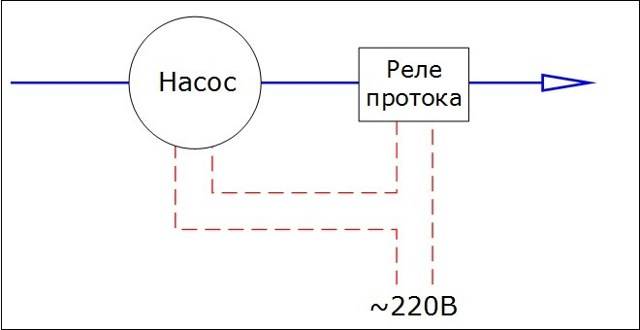
In any situation that causes the pump to run dry, there is insufficient or no water flow. There are devices that monitor this situation - relays and water flow controllers. Relays or flow sensors are electromechanical devices, controllers are electronic.
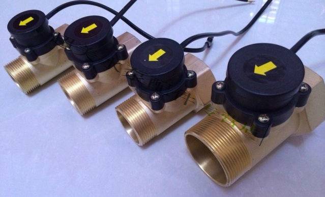
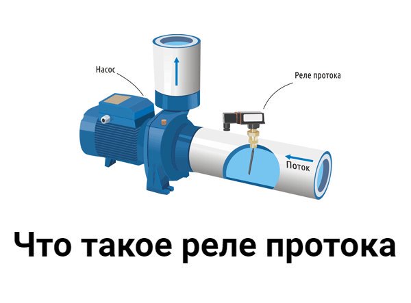
Relay (sensors) of the flow
There are two types of flow sensors - petal and turbine. Flap has a flexible plate that is in the pipeline. In the absence of water flow, the plate deviates from the normal state, contacts are activated that turn off the power to the pump.
Turbine flow sensors are somewhat more complicated. The basis of the device is a small turbine with an electromagnet in the rotor. In the presence of a flow of water or gas, the turbine rotates, an electromagnetic field is created, which is converted into electromagnetic pulses read by the sensor. This sensor, depending on the number of pulses, turns on / off the power to the pump.
flow controllers
Basically, these are devices that combine two functions: protection against dry running and a water pressure switch. Some models, in addition to these features, may have a built-in pressure gauge and check valve. These devices are also called electronic pressure switches.These devices cannot be called cheap, but they provide high-quality protection, serving several parameters at once, providing the pressure required in the system, turning off the equipment when there is insufficient water flow.
| Name | Functions | Parameters of operation of protection against dry running | Connecting dimensions | Producing country | Price |
|---|---|---|---|---|---|
| BRIO 2000M Italtecnica | Pressure switch + flow sensor | 7-15 sec | 1″ (25mm) | Italy | 45$ |
| AQUAROBOT TURBIPRESS | Pressure switch + flow switch | 0.5 l/min | 1″ (25mm) | 75$ | |
| AL-KO | Pressure switch + check valve + dry running protection | 45 sec | 1″ (25mm) | Germany | 68$ |
| Dzhileks automation unit | Pressure switch + idle protection + pressure gauge | 1″ (25mm) | Russia | 38$ | |
| Aquario automation unit | Pressure switch + idle protection + pressure gauge + check valve | 1″ (25mm) | Italy | 50$ |
In the case of using an automation unit, a hydraulic accumulator is an extra device. The system works perfectly on the appearance of a flow - the opening of a tap, the operation of household appliances, etc. But this is if the headroom is small. If the gap is large, both a GA and a pressure switch are needed. The fact is that the pump shutdown limit in the automation unit is not adjustable. The pump will only turn off when it reaches maximum pressure. If it is taken with a large headroom, it can create excess pressure (optimal - no more than 3-4 atm, anything higher leads to premature wear of the system). Therefore, after the automation unit, they put a pressure switch and a hydraulic accumulator. This scheme makes it possible to regulate the pressure at which the pump is turned off.
Fluid flow sensors
Liquid flow sensors are designed to indicate the flow of a liquid substance, determine the speed and measure the level of product flow.
Modern flow switches are highly sensitive and able to respond even to a weak flow of liquid in the pipeline. A variety of models allows the use of flow sensors to work with various types of liquid products, including aggressive and hazardous substances. Some manufacturers offer explosion-proof options that are safe for use in hazardous industries.
Scope of liquid flow sensors
Liquid flow switches are used to solve various problems in many industries:
- in water supply and sanitation systems to control water supply, maintain the operation of pumping equipment, organize wastewater disposal systems, sewer facilities, protect pumping equipment and engines from "dry running",
- in heating, cooling, ventilation and air conditioning systems to control the supply of water, refrigerant, special liquids, removal of waste liquids from the system,
- in the oil and gas sector to control the flow of gas, oil, oil products during transportation and storage,
- in metallurgy, steel industry in systems for supplying and discharging water and other liquids,
- in the chemical industry to work with aggressive and dangerous types of liquid products, water supply and discharge systems,
- in agriculture when automating feeding processes, in drinking bowls, in watering and irrigation systems, when working with liquid fertilizers,
- in the food industry to control the supply of various types of liquid food products, including mineral water, dairy and sour-milk products, alcoholic beverages, beer, etc.
Some types of liquid flow sensors are also suitable for working with gases, which greatly expands the possibilities of using devices in industry and everyday life.
Types of liquid flow switches and their purpose
Modern types of fluid flow switches have a common main purpose - to control the presence or absence of the flow of the working fluid in the pipeline. The differences lie in the principles of operation and the possibilities of using the sensors.
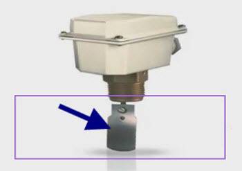
- Mechanical paddle flow switch is a device built into the pipe, equipped with a special blade. If there is flow in the pipeline, the vane deflects, causing the contacts to close and trigger the sensor. The paddle relay has practically no restrictions in use, is little subject to wear and does not require maintenance.
- Thermal flow switch monitors the presence of flow by measuring the level of dissipation of thermal energy from the built-in heating element. Depending on the rate of change in the temperature of the heating element, the flow is recorded, as well as its speed if this function is available. The hot-wire principle of flow measurement is not suitable for some hazardous liquids. To maintain the reliability of registration, it is necessary to maintain the cleanliness of the sensitive elements of the sensor. Some types of devices are not suitable for operation in conditions of constantly changing flow rates.
- Mechanical piston flow sensor works on the basis of a magnetic piston system. When there is flow, the built-in piston with magnet rises, causing the contacts to close and trigger the sensor. In the absence of flow, the piston returns to its original position.The piston transmitter is optimally suited for high pressure applications and is available in a variety of designs for mounting in the most convenient position.
- Operating principle ultrasonic liquid flow switch is based on the properties of the acoustic effect that occurs when ultrasonic pulses are transmitted through the product flow. At present, the devices that use the movement of ultrasonic vibrations by a moving stream are most widely used.
- flow indicators - these are devices with one or two windows for visual control and a rotating blade or a rotating shutter as a signaling device for the presence and direction of flow, in addition, there are pipe structures with devices for cleaning substances. In some models it is possible to receive electrical control output signals (relay, flow).


