- Practical examples of relay settings
- Connecting a new device
- Pump stopped turning off
- Situations that do not require adjustment
- Functional purpose of the flow switch
- The device and principle of operation of the pressure switch
- Overview of popular models
- Step-by-step instructions for adjusting the pressure switch
- Step by step instructions how to connect
- Connection to frequency converter
- To the water supply system
- When does automation need to be reset?
- Permissible relay failures
- The device of a double-circuit gas boiler
- The principle of operation of the boiler and its device
- Rules and selection criteria in the store
- Models for an apartment
- For the water supply system of a private house
- Trustworthy Instruments
- Genyo Lowara Genyo 8A
- Grundfos UPA 120
Practical examples of relay settings
Let's analyze the cases when the appeal to the adjustment of the pressure switch is really necessary. This usually happens when buying a new appliance or when frequent pump shutdowns occur. Also, setting will be required if you got a used device with downgraded parameters.
Connecting a new device
At this stage, you should check how correct the factory settings are and, if necessary, make some changes to the operation of the pump.
Image gallery
Photo from
We turn off the energy, completely empty the system of water until the pressure gauge reaches the “zero” mark.Turn on the pump and watch the readings. We remember at what value it turned off. Then we drain the water and remember the parameters at which the pump starts working again
We twist a large spring to increase the lower border. We make a check: we drain the water and remember the value of switching on and off. The second parameter should increase along with the first. Adjust until you get the desired result.
We perform the same actions, but with a small spring. You need to act carefully, since the slightest change in the position of the spring responds to the operation of the pump. Having slightly tightened or loosened the nut, we immediately check the result of the work
Having finished all the manipulations with the springs, we take the final readings and compare them with the initial ones. We also look at what has changed in the work of the station. If the tank began to be filled in a different volume, and the on / off intervals have changed, the setting was successful
Stage 1 - equipment preparation
Stage 2 - adjusting the turn-on value
Step 3 - adjusting the trip amount
Stage 4 - testing the system operation
To track the progress of work, it is recommended to write down all the data received on a piece of paper. In the future, you can return the initial settings or change the settings again.
Pump stopped turning off
In this case, we forcibly turn off the pumping equipment and act in the following order:
- We turn on, and wait until the pressure reaches the maximum mark - suppose 3.7 atm.
- We turn off the equipment and lower the pressure by draining the water - for example, up to 3.1 atm.
- Slightly tighten the nut on the small spring, increasing the value of the differential.
- We check how the cut-off pressure has changed and test the system.
- We adjust the best option by tightening and loosening the nuts on both springs.
If the cause was an incorrect initial setting, it can be solved without buying a new relay. It is recommended to regularly, once every 1-2 months, check the operation of the pressure switch and, if necessary, adjust the on / off limits.
Situations that do not require adjustment
There can be many reasons when the pump does not turn off or does not turn on - from a blockage in communications to engine failure. Therefore, before starting to disassemble the relay, you should make sure that the rest of the equipment of the pumping station is working properly.
If everything is in order with the rest of the devices, the problem is in the automation. We turn to the inspection of the pressure switch. We disconnect it from the fitting and wires, remove the cover and check two critical points: a thin pipe for connecting to the system and a block of contacts.
Image gallery
Photo from
To check if the hole is clean, it is necessary to dismantle the device for inspection, and if a blockage is found, clean it.
The quality of tap water is not ideal, so often the problem is solved by simply cleaning the inlet from rust and mineral deposits.
Even with devices with a high degree of protection against moisture, failures can occur due to the fact that the wire contacts are oxidized or burned.
To clean the contacts, use a special chemical solution or the simplest option - the finest sandpaper
You have to act very carefully
Plugged hydraulic tank connection
Relay inlet cleaning
Clogged electrical contacts
Cleaning the contact block.If the cleaning measures did not help, and the adjustment of the position of the springs was also in vain, most likely the relay is not subject to further operation and should be replaced with a new one
If the cleaning measures did not help, and the adjustment of the position of the springs was also in vain, most likely the relay is not subject to further operation and should be replaced with a new one.
Suppose you got an old but working device in your hands. Its adjustment takes place in the same order as the setting of a new relay. Before starting work, make sure that the device is intact, disassemble it and check that all contacts and springs are in place.
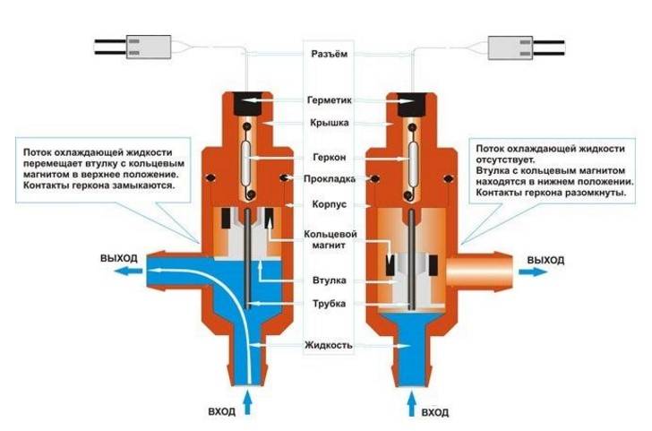


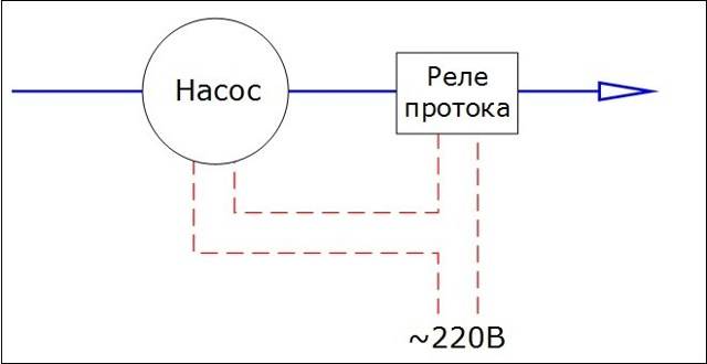
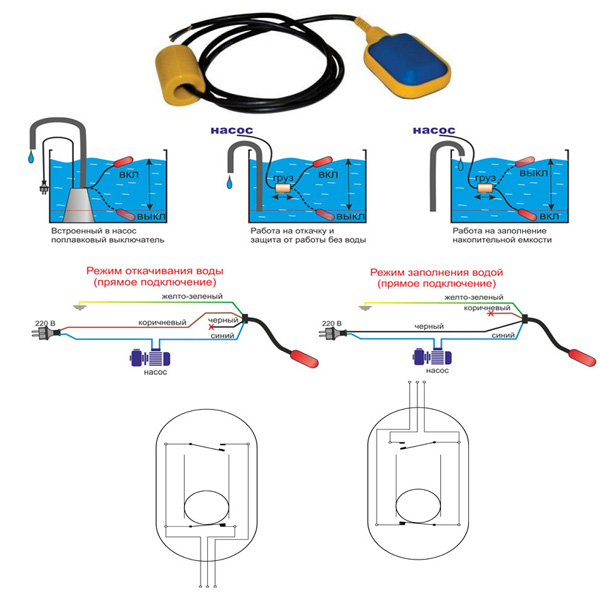
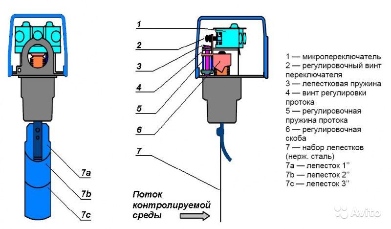
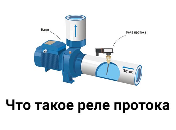
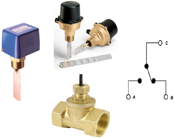
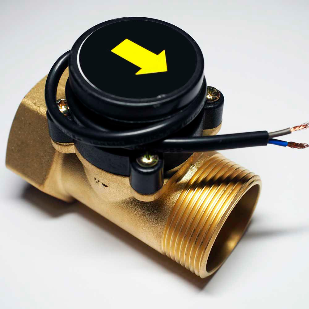
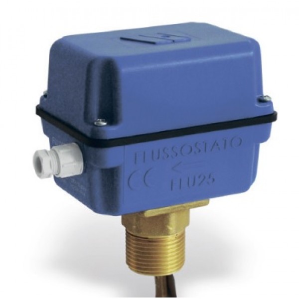
Functional purpose of the flow switch
In domestic water supply systems, the operation of a pumping station without water that threatens with an accident quite often occurs. A similar problem is called "dry running".
As a rule, the liquid cools and lubricates the elements of the system, thereby ensuring its normal performance. Even a short dry run leads to deformation of individual parts, overheating and failure of the equipment engine. The negative effects apply to both surface and deep pump models.
Dry running occurs for various reasons:
- wrong choice of pump performance;
- unsuccessful installation;
- violation of the integrity of the water pipe;
- low fluid pressure and lack of control over its level, for which a pressure switch is used;
- accumulated debris in the pumping pipe.
An automatic sensor is necessary in order to completely protect the device from the threats posed by lack of water. It measures, controls and maintains the constancy of the parameters of the water flow.
Pumping equipment equipped with a sensor has many advantages.It lasts longer, fails less often, consumes electricity more economically. There are also relay models for boilers
The main purpose of the relay is to independently turn off the pumping station in case of insufficient fluid flow power and turn it on after normalization of the indicators.
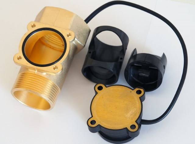
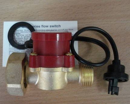
The device and principle of operation of the pressure switch
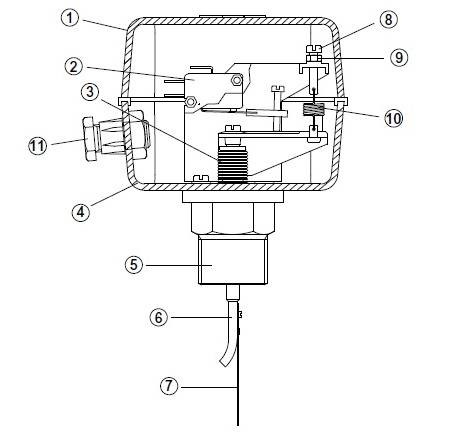
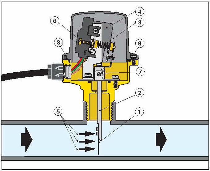
The pressure switch device of the pumping station is not complicated. The design of the relay includes the following elements.
Housing (see picture below).
- Flange for connecting the module to the system.
- Nut designed to adjust the shutdown of the device.
- A nut that regulates the compression force in the tank at which the unit will turn on.
- Terminals to which the wires coming from the pump are connected.
- Place for connecting wires from the mains.
- Ground terminals.
- Couplings for fixing electrical cables.
There is a metal cover on the bottom of the relay. If you open it, you can see the membrane and the piston.
The principle of operation of the pressure switch is as follows. With an increase in the compression force in the hydraulic tank chamber designed for air, the relay membrane flexes and acts on the piston. It sets in motion and activates the contact group of the relay. The contact group, which has 2 hinges, depending on the position of the piston, either closes or opens the contacts through which the pump is powered. As a result, when the contacts are closed, the equipment is started, and when they are opened, the unit stops.
Overview of popular models
There are two types of pressure switches: mechanical and electronic, the latter are much more expensive and rarely used.A wide range of devices from domestic and foreign manufacturers is presented on the market, facilitating the choice of the required model.
RDM-5 Dzhileks (15 USD) is the most popular high-quality model from a domestic manufacturer.
Characteristics
- range: 1.0 - 4.6 atm.;
- minimum difference: 1 atm.;
- operating current: maximum 10 A.;
- protection class: IP 44;
- factory settings: 1.4 atm. and 2.8 atm.
Genebre 3781 1/4″ ($10) is a Spanish-made budget model.
Characteristics
- case material: plastic;
- pressure: top 10 atm.;
- connection: threaded 1.4 inches;
- weight: 0.4 kg.
Italtecnica PM / 5-3W (13 USD) is an inexpensive device from an Italian manufacturer with a built-in pressure gauge.
Characteristics
- maximum current: 12A;
- working pressure: maximum 5 atm.;
- lower: adjustment range 1 - 2.5 atm.;
- upper: range 1.8 - 4.5 atm.
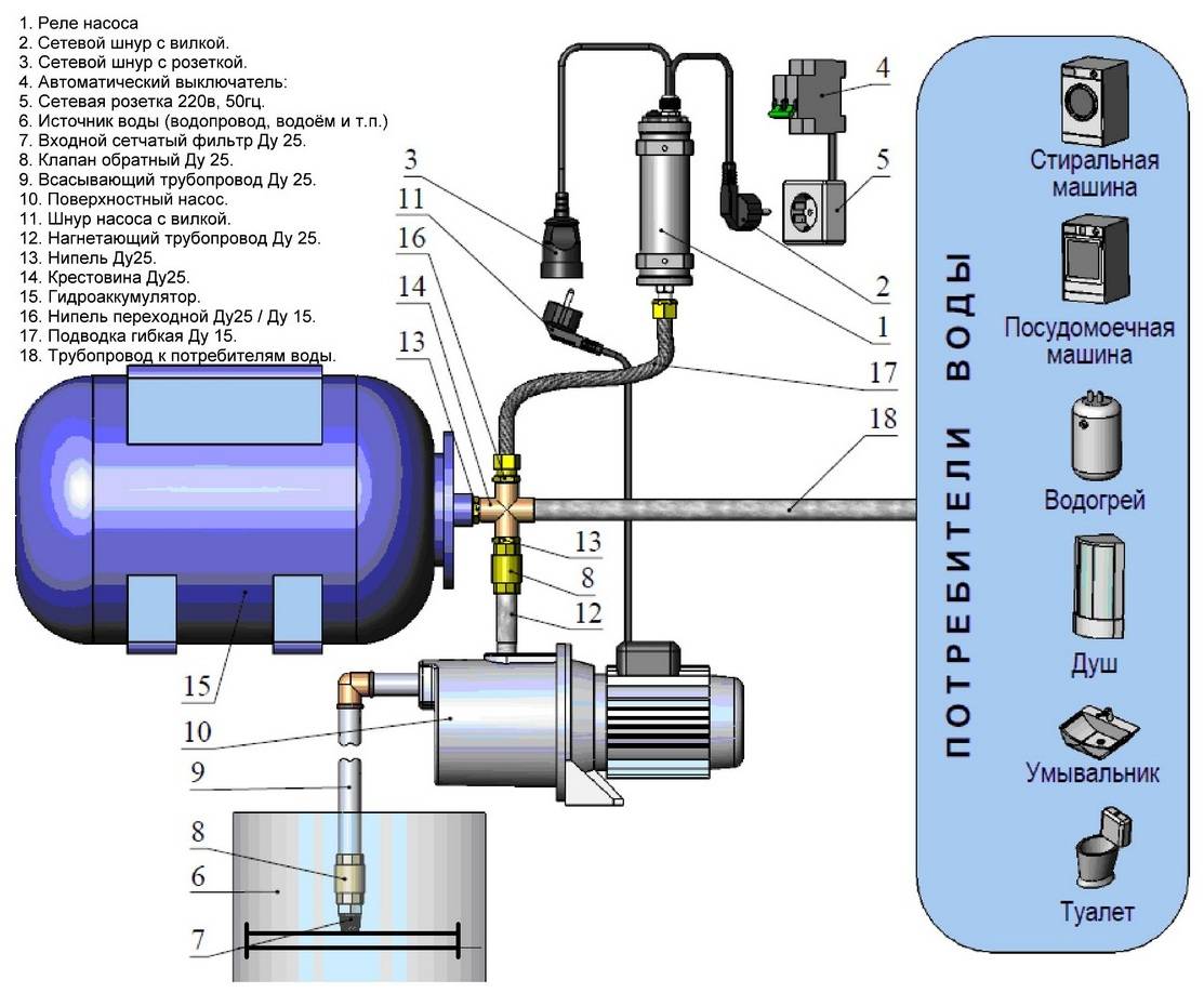
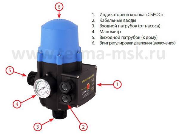
The pressure switch is the most important element in the water intake system, which provides automatic individual water supply to the house. It is located next to the accumulator, the operating mode is set by means of adjusting screws inside the housing.


When organizing autonomous water supply in a private house, pumping equipment is used to raise water. In order for the water supply to be stable, it is necessary to select it correctly, since each type has its own technical characteristics and features.
For efficient and trouble-free operation of the pump and the entire water supply system, it is necessary to purchase and install an automation kit for the pump, taking into account the characteristics of the well or well, the water level and its expected flow rate.
The vibration pump is chosen when the amount of water spent per day does not exceed 1 cubic meter.It is inexpensive, does not create problems during operation and maintenance, and its repair is simple. But if water is consumed from 1 to 4 cubic meters or water is located at a distance of 50 m, it is better to purchase a centrifugal model.
Usually the kit includes:
- operating relay, which is responsible for supplying and blocking voltage to the pump at the time of emptying or filling the system; the device can be immediately configured at the factory, and self-configuration for specific conditions is also allowed:
- a collector that supplies and distributes water to all points of consumption;
- pressure gauge for measuring pressure.
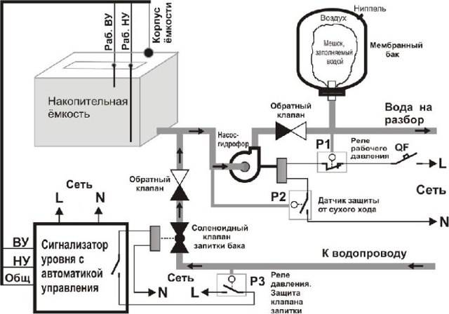
Manufacturers offer ready-made pumping stations adapted to specific requirements, but a self-assembled system will work most efficiently. The system is also equipped with a sensor that blocks its operation during dry running: it disconnects the engine from power.
The safety of the equipment operation is ensured by overload protection sensors and the integrity of the main pipeline, as well as a power regulator.
Step-by-step instructions for adjusting the pressure switch
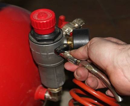
Step 1. Check the compressed air pressure in the accumulator. There is a rubber plug on the back of the tank, you need to remove it and get to the nipple. Check the pressure with an ordinary air pressure gauge, it should be equal to one atmosphere. If there is no pressure, pump in air, measure the data and after a while check the indicators. If they decrease - a problem, you need to look for the cause and eliminate it. The fact is that most equipment manufacturers sell hydraulic accumulators with pumped air. If it is not available when buying, then this indicates a marriage, it is better not to purchase such a pump.
First you need to measure the pressure in the accumulator
Step 2. Disconnect electrical power and remove pressure regulator housing protective cover. It is fixed with a screw, removed with an ordinary screwdriver. Under the cover there is a contact group and two springs compressed by 8 mm nuts.
To adjust the relay, you must remove the housing cover
Big spring. Responsible for the pressure at which the pump turns on. If the spring is fully tightened, then the motor switch-on contacts will be constantly closed, the pump turns on at zero pressure and constantly works.
Small spring. Responsible for turning off the pump, depending on the degree of compression, the water pressure changes and reaches its maximum value
Please note, not the optimal working, but the maximum according to the technical characteristics of the unit.
Relay factory settings need to be adjusted
For example, you have a delta of 2 atm. If in this case the pump is turned on at a pressure of 1 atm, then it will turn off at 3 atm. If it turns on at 1.5 atm, then it turns off, respectively, at 3.5 atm. and so on. Always the difference between the pressure on and off the electric motor will be 2 atm. You can change this parameter by changing the compression ratio of the small spring. Remember these dependencies, they are needed to understand the pressure control algorithm. The factory settings are set to turn on the pump at 1.5 atm. and shutdown at 2.5 atm., delta is 1 atm.
Step 3. Check the actual operating parameters of the pump. Open the tap to drain the water and slowly release its pressure, constantly monitor the movement of the pressure gauge needle. Remember or write down at what indicators the pump turned on.
When the water is drained, the arrow indicates a decrease in pressure
Step 4. Continue monitoring until the moment of shutdown. Also note down the values at which the electric motor cuts out. Find out the delta, subtract the smaller from the larger value. This parameter is needed so that you can navigate at what pressures the pump will turn off if you adjust the compression force of the large spring.
Now you need to notice the values at which the pump turns off
Step 5. Shut off the pump and loosen the small spring nut about two turns. Turn on the pump, fix the moment it turns off. Now the delta should decrease by about 0.5 atm., The pump will turn off when the pressure reaches 2.0 atm.
Using the wrench, you need to loosen the small spring a couple of turns
Step 6. You need to ensure that the water pressure is in the range of 1.2–1.7 atm. As mentioned above, this is the optimal mode. Delta 0.5 atm. you have already installed, you need to lower the switching threshold. To do this, you need to release a large spring. For the first time, turn the nut, check the starting period, if necessary, fine-tune the compression force of the large spring.


Large spring adjustment
You will have to start the pump several times until you achieve switching on at 1.2 atm., And turning off at a pressure of 1.7 atm. It remains to replace the housing cover and put the pumping station into operation. If the pressure is correctly adjusted, the filters are constantly in good condition, then the pump will work for a long period of time, there is no need to do any special maintenance.
Pump Relay Selection Criteria
Step by step instructions how to connect
A detailed diagram of the installation of the pressure sensor is in the instructions with which the device is sold. In general, the sequence of steps is the same.
Connection to frequency converter
The sensor is connected to the inverter in the following order:
- mount the sensor on the pipeline, connect the device to the high-frequency converter with a signal cable;
- in accordance with the diagram given in the documentation, connect the wires to the appropriate terminals;
- configure the software part of the converter and check the operation of the bundle.
To prevent interference and correct operation of the inverter, a shielded signal cable is used for laying.
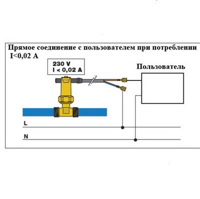
To the water supply system
A typical pipeline mount transmitter requires a stub with five leads:
- water inlet and outlet;
- outlet to the expansion tank;
- under the pressure switch, as a rule, with an external thread;
- pressure gauge outlet.
A cord from the pump is connected to the sensor to control the on or off. The power supply is provided by a cable that is laid to the shield.
When does automation need to be reset?
There are various reasons why a pump may not provide the required value. We briefly list the most common:
- the equipment operates at a large suction depth, cannot achieve the water supply of the required force;
- pump impeller wear, cannot pump water to the required force;
- increased wear of sealing glands, air leakage;
- the need to supply water with high pressure to a multi-storey building or a highly located storage tank;
- Water-consuming mechanisms require more pressure.
In these and other similar cases, it will be necessary to change the factory settings.
Permissible relay failures
Several breakdowns that are distinctive for pressure switches are noted. In many cases, they are simply exchanged for new devices. But there are small problems that can be removed personally without the help of a professional.
If the pressure switch was found to be the object of a malfunction, the professional will insist on replacing the device. All service actions for cleaning and replacing contacts cost the client more than purchasing and installing a new device
More often than others, a breakdown occurs, characterized by air leakage from relay with the receiver turned on. In this embodiment, the starting valve may be the culprit. You just need to replace the gasket and the problem will be fixed.
Frequent turning on of the air blower indicates loosening and displacement of the pressure bolts. Here you will need to double-check the threshold for turning on and off the relay and adjust them in accordance with the instructions in the previous section.
The device of a double-circuit gas boiler
In order to understand the principle of operation of a gas double-circuit boiler, it is necessary to understand its device. It consists of many individual modules that heat the heating medium in the heating circuit and switch over to the DHW circuit. The well-coordinated work of all components allows you to count on the trouble-free operation of the equipment. Knowing the device of a double-circuit boiler, you can understand its principle of operation.
We will not consider the device of double-circuit boilers with an accuracy of a screw, since it is enough for us to understand the purpose of the main components. Inside the cauldron we will find:
Device models with two circuits: heating and DHW circuit.
- A burner located in an open or closed combustion chamber is the heart of any heating boiler.It heats the coolant and generates heat for the operation of the DHW circuit. To ensure accurate maintenance of the set temperature, it is endowed with an electronic flame modulation system;
- Combustion chamber - the above burner is located in it. It can be open or closed. In a closed combustion chamber (or rather, above it) we will find a fan responsible for forcing air and for removing combustion products. It is he who is the source of quiet noise when the boiler is turned on;
- Circulation pump - provides forced circulation of the coolant through the heating system and during the operation of the DHW circuit. Unlike the combustion chamber fan, the pump is not a source of noise and operates as silently as possible;
- Three-way valve - it is this thing that is responsible for switching the system to the hot water generation mode;
- The main heat exchanger - in the device of a double-circuit wall-mounted gas boiler, it is located above the burner, in the combustion chamber. Here, the heating medium used in the heating circuit or in the DHW circuit for heating water is heated;
- Secondary heat exchanger - it is in it that hot water is prepared;
- Automation - it controls the parameters of the equipment, checks the temperature of the coolant and hot water, controls the modulation, turns on and off various nodes, controls the presence of a flame, fixes errors and performs other useful functions.
In the lower part of the buildings there are branch pipes for connecting the heating system, pipes with cold water, pipes with hot water and gas.
Some models of gas double-circuit boilers use dual heat exchangers. But the principle of operation remains almost the same.
It can be seen that the gas column device differs only in the absence of a heating circuit.
We found out the device of a double-circuit wall-mounted gas boiler - it seems a little complicated, but if you understand the purpose of certain nodes, then the difficulties will disappear. Here we can note the similarity with a gas instantaneous water heater, from which a burner with a heat exchanger remains here. Everything else is taken from wall-mounted single-circuit boilers. The undoubted advantage is the presence of a built-in piping - this is an expansion tank, a circulation pump and a safety group.


When analyzing the principle of operation and the device of a gas double-circuit boiler, it should be noted that the water from the DHW circuit never mixes with the coolant. The coolant is poured into the heating system through a separate pipe connected to the heating. Hot water is prepared by part of the coolant circulating through the secondary heat exchanger. However, we will talk about this a little later.
The principle of operation of the boiler and its device
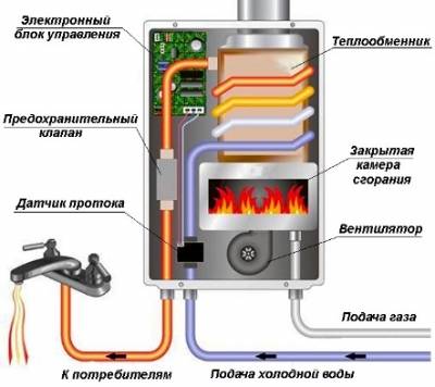
Image 1. Hydraulic diagram of a double-circuit boiler in heating mode.
Gas appliances with two heating circuits have the following principle of operation. The heat of the burnt natural gas is transferred to the heat exchanger, which is located above the gas burner. This heat exchanger is included in the heating system main, that is, the heated water in it will circulate through the heating system. Water circulation is carried out by means of a pump built into the boiler. For the preparation of hot water, the double-circuit device is equipped with a secondary heat exchanger.
The presented diagram in PICTURE 1 shows the ongoing work processes and equipment arrangement:
- Gas-burner.
- Circulation pump.
- Three-way valve.
- DHW circuit, plate heat exchanger.
- Heating circuit heat exchanger.
- D - input (return) of the heating system for heating;
- A - supply of ready-made coolant for heating appliances;
- C - cold water inlet from the main;
- B - output of ready hot water for sanitary needs and domestic use.
The principle of preparing water for domestic hot water is as follows: the heated water in the first heat exchanger (5), which is located above the gas burner (1) and is designed to heat the heating circuit, enters the second plate heat exchanger (4), where it transfers its heat to the domestic hot water circuit.
As a rule, double-circuit boilers have a built-in expansion tank to compensate for changes in the volume of the coolant.
The scheme of a double-circuit boiler allows you to produce hot water and heat it for heating only in certain modes.
The design of a double-circuit gas boiler.
Using the boiler for both domestic hot water and heating at a certain point in time is not possible. For example, during operation of the device, the heating system is heated at a given temperature, the process of maintaining the temperature is controlled by the automatic boiler, and the circulation of the coolant through the heating network is carried out by a pump.
At a certain moment, the hot water tap for domestic needs is opened, and as soon as the water begins to move along the DHW circuit, a special flow sensor installed in the boiler is activated. With the help of a three-way valve (3), the water flow circuits in the boiler are reconfigured.Namely, the water heated in the heat exchanger (5) ceases to flow into the heating system and is supplied to the plate heat exchanger (4), where it transfers its heat to the DHW system, that is, the cold water that has arrived from the pipeline (C) is also heated through the pipeline (B) served to consumers of an apartment or house.
At this moment, the circulation goes in a small circle and the heating system does not heat up for the duration of the DHW use. As soon as the tap on the DHW intake is closed, the flow sensor is triggered and the three-way valve opens the heating circuit again, further heating of the heating system occurs.
Most often, the scheme of the device of a double-circuit gas boiler implies the presence of a plate heat exchanger. As already mentioned, its purpose is to transfer heat from the heating circuit to the water supply circuit. The principle of such a heat exchanger is that sets of plates with hot and cold water are assembled into a package where heat transfer occurs.
The connection is made in a hermetic way: this prevents the mixing of liquids from different circuits. Due to the constant change in temperature, processes of thermal expansion of the metal from which the heat exchanger is made occur, which contributes to the mechanical removal of the resulting scale. Plate heat exchangers are made of copper or brass.
Connection diagram for a double-circuit boiler.
There is a double-circuit boiler scheme, which includes a combined heat exchanger.
It is located above the gas burner and consists of double tubes. That is, the heating circuit pipe contains a hot water pipe inside its space.
This scheme allows you to do without a plate heat exchanger and slightly increase the efficiency in the process of preparing hot water.
The disadvantage of boilers with a combined heat exchanger is that scale is deposited between the thin walls of the tubes, as a result of which the operating conditions of the boiler deteriorate.
Rules and selection criteria in the store
A wide range of settings allows you to install an electronic relay in any home water supply system. It will work well with both submersible and surface pumps.
Parameters that are taken into account when choosing:
- the relay works in conjunction with a hydraulic accumulator;
- maximum pressure generated by the pump;
- installation method, dimensions of connecting pipes;
- electric motor power;
- voltage stability;
- the degree of deterioration of the system;
- degree of protection of the device.
Models for an apartment
For relays used in an apartment, it is important to have a wide range of settings and the ability to set a password:
| Device and its parameters | T-Kit SWITCHMATIC 2/2+ | RDE-Light | RDE-M-St |
| Rvkl range, bar | 0,5-7,0 | 0,2-9,7 | 0,2-6,0 |
| Roff range, bar | 8,0-12,0 | 0,4-9,90 | 0,4-9,99 |
| Max Pump power, kW | 2,2 | 1,5 | 1,5 |
| Dry run protection | + | + | + |
| Pump on/off delay | + | + | + |
| Break protection | — | — | + |
| Leak protection | — | — | + |
| Watering Mode | — | — | — |
| Protection against frequent switching on | — | — | + |
| Password | — | + | + |
| Breakdown of the hydraulic accumulator | — | — | — |
| Remote sensor | — | — | + |
For the water supply system of a private house
The relays used in a private house are distinguished by an extended list of pump protection modes:
| Device and its parameters | RDE G1/2 | RDE 10.0-U | RDE-M |
| Rvkl range, bar | 0,5-6,0 | 0,2-9,7 | 0,2-9,7 |
| Roff range, bar | 0,8-9,9 | 3,0-9,9 | 3,0-9,9 |
| Max Pump power, kW | 1,5 | 1,5 | 1,5 |
| Dry run protection | + | + | + |
| Pump on/off delay | + | + | + |
| Break protection | + | + | + |
| Leak protection | + | + | + |
| Watering mode | + | + | + |
| Protection against frequent switching on. | + | + | + |
| Password | — | + | + |
| Breakdown of the hydraulic accumulator | — | — | + |
| Remote sensor | — | — | — |
Trustworthy Instruments
Among the entire range of relays, two models are most in demand, located in approximately the same price category - about $ 30. Let's consider their characteristics in more detail.


Genyo Lowara Genyo 8A
Development of a Polish company engaged in the production of electronic equipment for control systems. It is intended for application in household water supply systems.
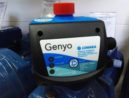 Genyo allows for automatic pump control: starting and shutting down based on actual water consumption, preventing any pressure fluctuations during operation. Also, the electric pump is protected from running dry.
The main purpose is to control the pump and control the pressure in the pipes during operation. This sensor starts the pump when the water flow exceeds 1.6 liters per minute. It consumes 2.4 kW of electricity. The operating temperature range is from 5 to 60 degrees.
Grundfos UPA 120
Manufactured in factories in Romania and China. Maintains the stability of the water supply in rooms equipped with individual water supply systems. Prevents pumping units from idling.
The Grundfos brand relay is equipped with a high protection class, allowing it to endure almost any load. Electricity consumption in it is about 2.2 kW
The automation of the device starts at a flow rate of 1.5 liters per minute. The boundary parameter of the covered temperature range is 60 degrees. The unit is produced in compact linear dimensions, which greatly facilitate the installation process.


