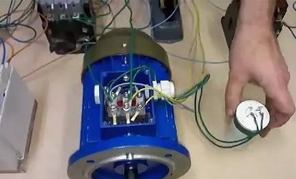
- Basic characteristics of the current relay
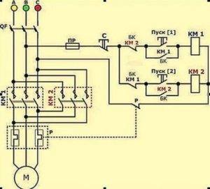
- Joint installation of relay and contactor
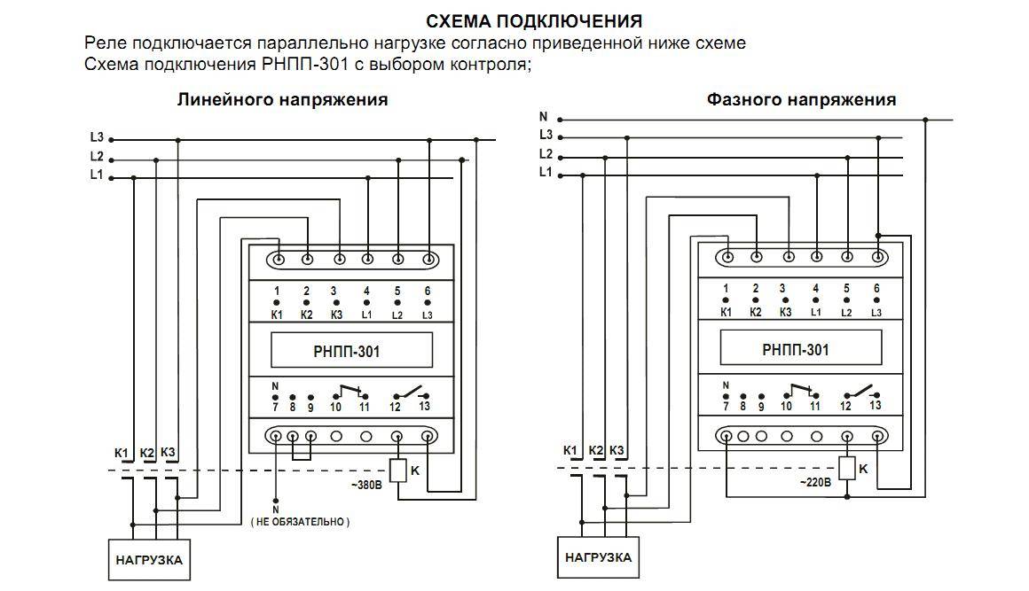
- Schemes of application and connection of the phase and voltage control relay RNL-1
- Installation of switching devices on the relay output
- Types of thermal protection relay
- General settings of the three-phase relay
- Other settings
- Relay selection
- How to connect a control device
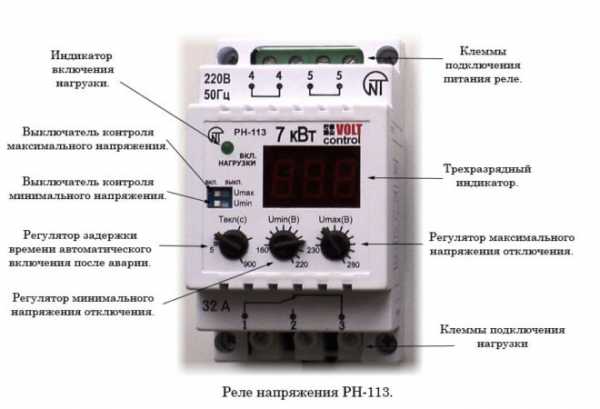
- Structural elements of the product
- How to set up a fixture
- Marking of the phase control device
Basic characteristics of the current relay
The main characteristic of the thermal protection switch is the pronounced dependence of the response time on the current flowing through it - the larger the value, the faster it will work. This indicates a certain inertia of the relay element.
The directed movement of charge carrier particles through any electrical appliance, a circulation pump and an electric boiler, generates heat. At rated current, its permissible duration tends to infinity.
And at values exceeding the nominal values, the temperature rises in the equipment, which leads to premature wear of the insulation.
An open circuit instantly blocks a further increase in temperature indicators. This makes it possible to prevent overheating of the engine and prevent an emergency failure of the electrical installation.
The rated load of the motor itself is a key factor in determining the choice of the device. An indicator in the range of 1.2-1.3 indicates successful operation with a current overload of 30% over a time period of 1200 seconds.
The duration of the overload can adversely affect the state of electrical equipment - with a short exposure of 5-10 minutes, only the motor winding, which has a small mass, heats up. And with prolonged heating, the entire engine heats up, which is fraught with serious damage. Or it may even be necessary to replace the burned-out equipment with a new one.
In order to protect the object from overload as much as possible, it is necessary to use a thermal protection relay specifically for it, the response time of which will correspond to the maximum allowable overload indicators of a particular electric motor.
In practice, it is not practical to assemble a voltage control relay for each type of motor. One relay element is used to protect engines of various designs. At the same time, it is impossible to guarantee reliable protection in the full operating interval, limited by the minimum and maximum loads.
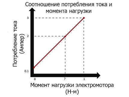
An increase in current indicators does not immediately lead to a dangerous emergency condition of the equipment. It will take some time before the rotor and stator reach the limit temperature.
Therefore, it is not absolutely necessary that the protective device respond to every, even a slight increase in current. The relay should switch off the motor only in cases where there is a danger of rapid wear of the insulating layer.
Joint installation of relay and contactor
An additional contactor is installed when the switching currents are too high.Often, installing a relay together with a contactor is cheaper than buying an ILV, which will correspond to the parameters of the electron flow.
In this case, there is one requirement for the rated current of the control element - it must exceed the value at which the contactor operates. The latter will completely take over the current load.
This connection option has one, but quite significant, drawback - reduced performance. It is due to the fact that the time required for the reaction of the contactor is added to the milliseconds required for the control device to operate.
Based on this, when choosing both devices, you need to pay attention to the highest possible performance of each of them.
When connecting this bundle, the phase wire from the VA is connected to a normally open contact.
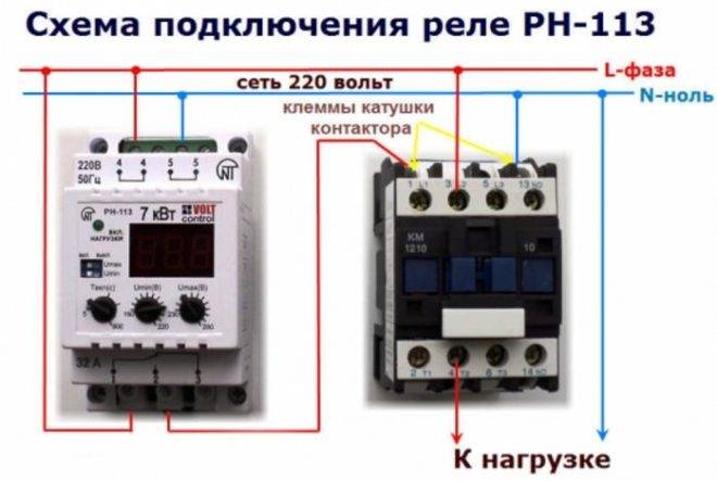
It is the input of the contactor circuit. The phase input of the RKN must be connected via a separate cable. It can be connected to the contactor input terminal or to the VA output terminal.


Since the phase input of the control element is connected with a conductor of a smaller cross section, it is necessary to pay attention to the reliability of the connection. To prevent it from falling out of the socket in which the thicker cable is located, both wires must be twisted together and fixed with solder or crimped with a special sleeve
When performing installation, make sure that the conductor suitable for the relay is firmly fixed. To connect the RKN output to the contactor solenoid terminal, a cable with a diameter of 1 - 1.5 mm2 is used. The zero of the control element and the second terminal of the coil are connected to the zero bus.
The output of the contactor is connected to the distribution bus using a power phase conductor.
Schemes of application and connection of the phase and voltage control relay RNL-1
The model consumes less than 2 VA. After normalization of the voltage, the control device switches on the power supply again after a period of time specified in the factory settings.
Advantages of the phase control relay In comparison with other emergency shutdown devices, these electronic relays have a number of significant advantages: in comparison with the voltage control relay, it does not depend on the influence of the EMF of the supply network, since its operation is tuned from the current; allows you to detect abnormal surges not only in the three-phase power supply network, but also from the load side, which allows you to expand the range of protected components; Unlike relays that work to change the current in electric motors, this equipment also allows you to fix the voltage parameter, providing control over several parameters; is able to determine the imbalance of supply voltage levels due to uneven loading of individual lines, which is fraught with overheating of the motor and a decrease in insulation parameters; does not require the formation of an additional transformation on the part of the operating voltage
A burnt motor stator winding can be said to be a common occurrence where it was not planned to introduce relay control into the control circuit. Based on all the technical and technological factors described, it becomes obvious the importance of using this type of relay, not only for cases of operation of electric motors, but also for generators , transformers and other electrical equipment. If foreign manufacturers label according to one canon, then domestic ones - according to others.
In this regard, it is necessary to constantly monitor the state of the phases, carried out using a three-phase voltage monitoring relay installed in the network.
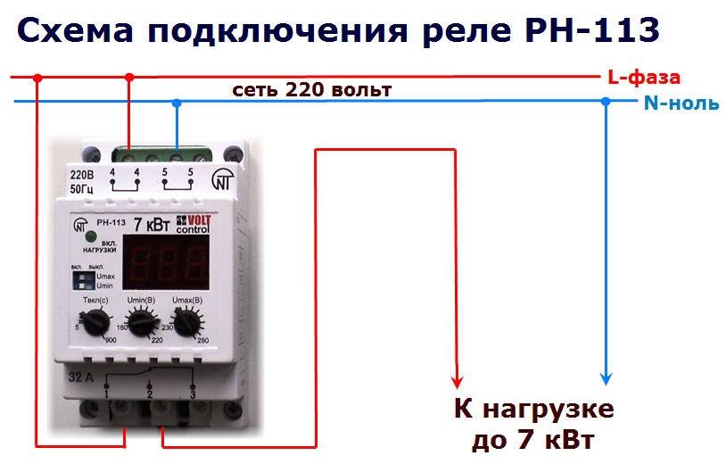
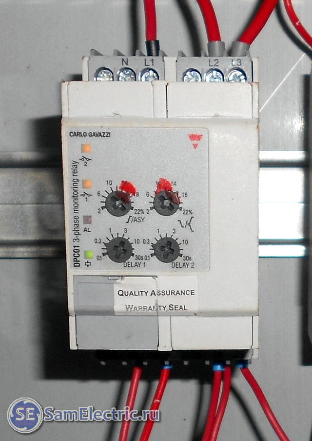
This is how one of the voltage control relay models looks like.
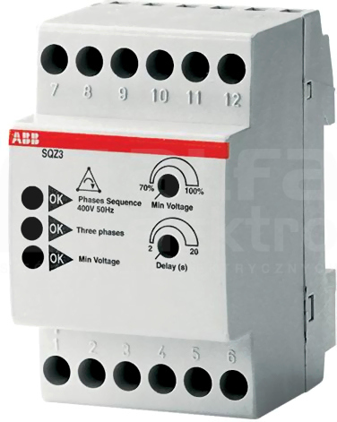
In practice, it is used to control the presence of U and the correct symmetry. If any of the phases exceeds the set values, the relay responsible for this circuit is activated, and the rest of the load, provided that it is within the desired range, continues to work. The next two letters A are regulation using a potentiometer and the type of mounting under the DIN rail.
Phase reversal detection is important if a motor running in reverse could damage the driven machine or, worse, cause physical injury to service personnel. The maximum voltage is V. This situation most often occurs due to a connection error. The number of goods produced exceeds units.
Installation of switching devices on the relay output
Not all models provide the full range of settings for the above parameters. By setting each of them in one position or another, the required configuration is created.
It is important to note that the scope of the product depends on their types of voltage phase control relays EL: 11 and 11 MT - protection of power supplies, participation in the ATS system, power supply of converters and generator sets. If the voltage of the main input is normal, then the relay contact KV1
Phase Reversal Detection Maintenance is in progress on motor equipment.
The connected load is formed evenly for each of the 3 phases. This makes it easy to connect a three-phase voltage monitoring relay to an electrical circuit, following the rules that are the same for all types of these devices.This device monitors a three-phase network when one or more phases are broken, the phase sequence is incorrect, the voltage is unbalanced, or the phases are unbalanced. A vivid example is a screw-type compressor, which, if connected incorrectly and turned on for more than five seconds, leads to a breakdown of an expensive product. The schematic diagram of the device is shown below.
Thus, control occurs automatically, in case of an emergency, the relay disconnects the load, and when the network parameters are restored, it turns on the voltage of the three-phase network automatically. Additional pluses include control of the minimum and maximum U, hysteresis function for 3-phase current. This allows you to significantly increase their power. The products of this enterprise are actively used both at civilian facilities and in large industrial organizations.
Connection and operation of the phase control relay EL-11E
Types of thermal protection relay
It should be noted that different types of thermal protection modules for electric power units are presented on the modern market of electrical products. Each of these types of devices is used in a specific situation and for a specific type of electrical equipment. The main types of thermal protection relays include the following designs.
- RTL is an electromechanical device that provides high-quality thermal protection of three-phase electric motors and other power plants from critical overloads in current consumption. In addition, this type of thermal relay protects the electrical installation in case of imbalance in the supply phases, prolonged start-up of the device, as well as in case of mechanical problems with the rotor: shaft jamming, and so on. The device is mounted on the PML contacts (magnetic starter) or as an independent element with a KRL terminal block.
- PTT is a three-phase device designed to protect electric motors with a squirrel-cage rotor from current overloads, imbalance between the supply phases and mechanical damage to the rotor, as well as from delayed starting torque. It has two installation options: as an independent device on the panel or combined with PME and PMA magnetic starters.
- RTI is a three-phase version of an electrothermal release that protects an electric motor from thermal damage to the windings when the consumption current is critically exceeded, from a long starting torque, asymmetry of the supply phases and from mechanical damage to the moving parts of the rotor. The device is mounted on magnetic contactors KMT or KMI.
- TRN is a two-phase device for electrical thermal protection of electric motors, which provides control of the duration of the start-up and current in normal operating mode. Resetting contacts to their original state after an emergency operation is carried out only manually. The operation of this release is completely independent of the ambient temperature, which is important for hot climates and hot industries.
- RTC is an electrothermal release, with which you can control a single parameter - the temperature of the metal case of the electrical installation. Control is carried out using a special probe. If the critical temperature value is exceeded, the device disconnects the electrical installation from the power line.
- Solid-state - a thermal relay that does not have any moving elements in its design.The operation of the release does not depend on the temperature regime in the environment and other characteristics of the atmospheric air, which is important for explosive industries. Provides control over the duration of the acceleration of electric motors, the optimal load current, breakage of phase wires and jamming of the rotor.
- RTE is a protective thermal relay, which is essentially a fuse. The device is made of a metal alloy with a low melting point, which melts at critical temperatures and breaks the circuit that feeds the electrical installation. This electrical product is mounted directly into the body of the electric power plant in a regular place.
It can be seen from the above information that there are currently several different types of electrothermal relays. All of them are used to solve a single task - to protect electric motors and other power electrical installations from current overloads with an increase in the temperatures of the working parts of the units to critical values.


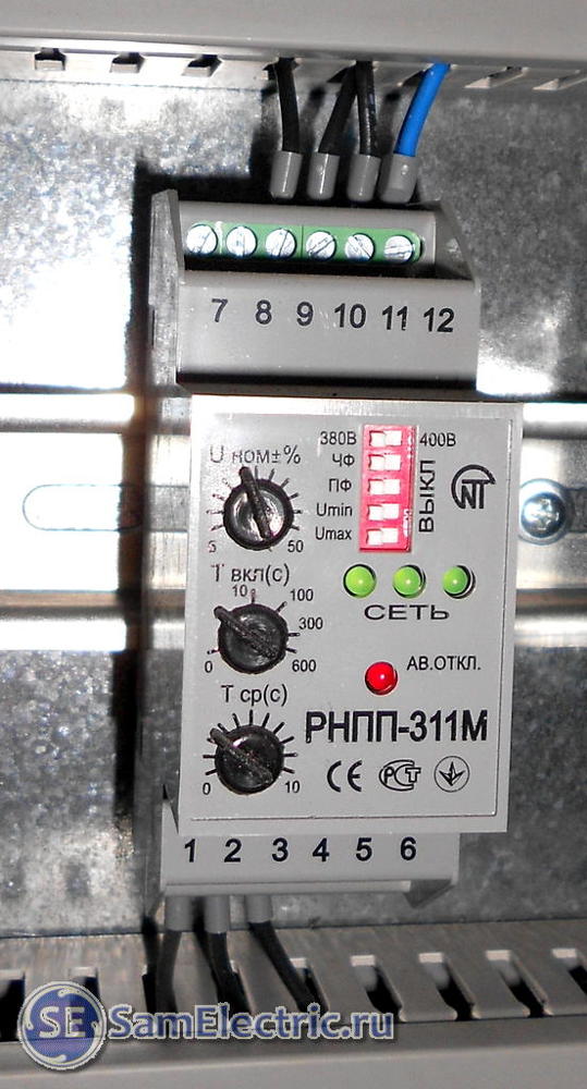


General settings of the three-phase relay
The initial settings are of great importance for the further operation of the voltage relay. The order of their implementation can be considered on the example of a typical model VP-380V, shown in the figure.
After the relay is connected to the electrical circuit, power is supplied to it. The display will show all the necessary information:
- Flashing digits indicate that there is no mains voltage.
- If dashes appear on the display, this means a change in the phase sequence or the absence of one of them.
- When the parameters of the electrical network correspond to the norm, and the device is connected correctly, then after about 15 seconds, contacts No. 1 and 3 close, power is supplied to the contactor coil and then to the network. That is, the device already monitors the state of all three phases.
- The display screen may flash for a very long time. This means that the contactor does not turn on. This situation most often occurs due to a connection error.
The three-phase voltage relay itself is configured using two setting buttons with printed triangles, which are located to the right of the screen. On the top button, the triangle is pointing up, and on the bottom - pointing down. To set the maximum shutdown limit, the top button is pressed. In this position, it is held for 2-3 seconds. After that, a number will appear in the center row of the screen, indicating the factory level. Further, the upper button should be pressed until the desired value of the upper shutdown limit is set.
Setting the lower limit is carried out in the same way, only in this case the lower button is used. At the end of the setup, the device will automatically reprogram after about 10 seconds.
Other settings
The three-phase voltage relay has many adjustments and settings. The correct setting of the re-off time is essential for ensuring the correct operation of the appliance.
To the right of the display, between the buttons with triangles, there is another control and adjustment button, with a printed clock icon. It must be pressed and held, after which the value set by the manufacturer will appear on the screen. Typically, the time interval is set to 15 seconds.
The importance of this function is shown as follows. In case of voltage drops exceeding the maximum permissible values, the relay disconnects the network
After normalization of the voltage, the control device switches on the power supply again after a period of time specified in the factory settings. This is the already known 15 seconds. This value can be changed, for example, downwards. This operation is performed by scrolling the factory check digit using the top or bottom button. The number on the screen will increase or decrease accordingly.
It is also easy to adjust the phase imbalance - the interval between the voltage values \u200b\u200bin different phases. To configure, you need to simultaneously press two buttons with triangles. The screen will display 50 V, which means that the power supply to the network will stop at this value of the phase imbalance. The desired parameter is set by the upper or lower button in the direction of decreasing or increasing.
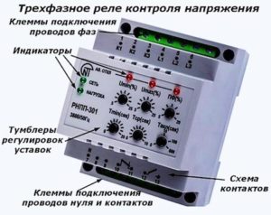
Voltage monitoring relay 3-phase
Three-phase RCD
Wiring diagram of a three-phase electric motor
Connecting a three-phase motor to a three-phase network
Three-phase motor reverse circuit
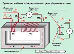
Scheme connection of a three-phase meter through current transformers
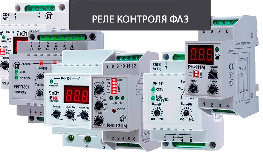
Relay selection
The choice of the type of relay we need depends directly on the technical characteristics of the connected device and the relay itself. Consider which relay is better for us to choose using the example of connecting an ATS (automatic backup power input). First, we determine the connection option we need with or without a neutral wire.


Then we find out the parameters of the relay itself that we need.To connect an ATS, the following performance characteristics are required in this device: sticking and phase failure control, sequence control; the delay should be 10-15 seconds; and there must be control over fluctuations of a given voltage below or above the threshold we need. To connect according to the neutral wire scheme, visual control is required for each phase. When connecting ATS, you can choose the type of relay EL11.
How to connect a control device
The designs of the relays that control the phases, with all the wide range of products available, have a unified body.
Structural elements of the product
Terminal blocks for connecting electrical conductors, as a rule, are displayed on the front of the case, which is convenient for installation work.
The device itself is made for installation on a DIN rail or simply on a flat plane.
The terminal block interface is usually a standard reliable clamp designed for mounting copper (aluminum) lived up to 2.5 mm2.
The front panel of the instrument contains the setting knob(s) as well as the light control indication. The latter shows the presence / absence of the supply voltage, as well as the state of the actuator.
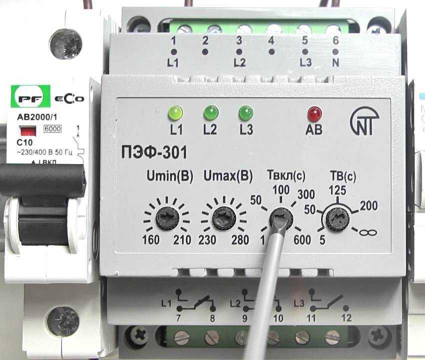
Potentiometer setting elements: 1 – alarm indicator; 2 - indicator of the connected load; 3 – mode selection potentiometer; 4 - adjustment of the level of asymmetry; 5 – voltage drop regulator; 6 - time delay adjustment potentiometer
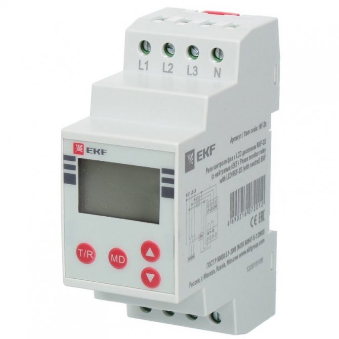
Three-phase voltage is connected at the operating terminals of the device, marked with the corresponding technical symbols (L1, L2, L3).
Installation of a neutral conductor on such devices is usually not provided, but this moment is specifically determined by the design of the relay - the type of model.
For connection with control circuits, a second interface group is used, usually consisting of at least 6 working terminals.
One pair of the contact group of the relay switches the coil circuit of the magnetic starter, and through the second pair the control circuit of the electrical equipment.
Everything is quite simple. However, each individual relay model may have its own connection features.
Therefore, when using the device in practice, you should always be guided by the accompanying documentation.
How to set up a fixture
Again, depending on the version, the design of the product can be equipped with different circuit settings and adjustment options.
There are simple models that provide for constructively outputting one or two potentiometers to the control panel. And there are devices with advanced customization items.
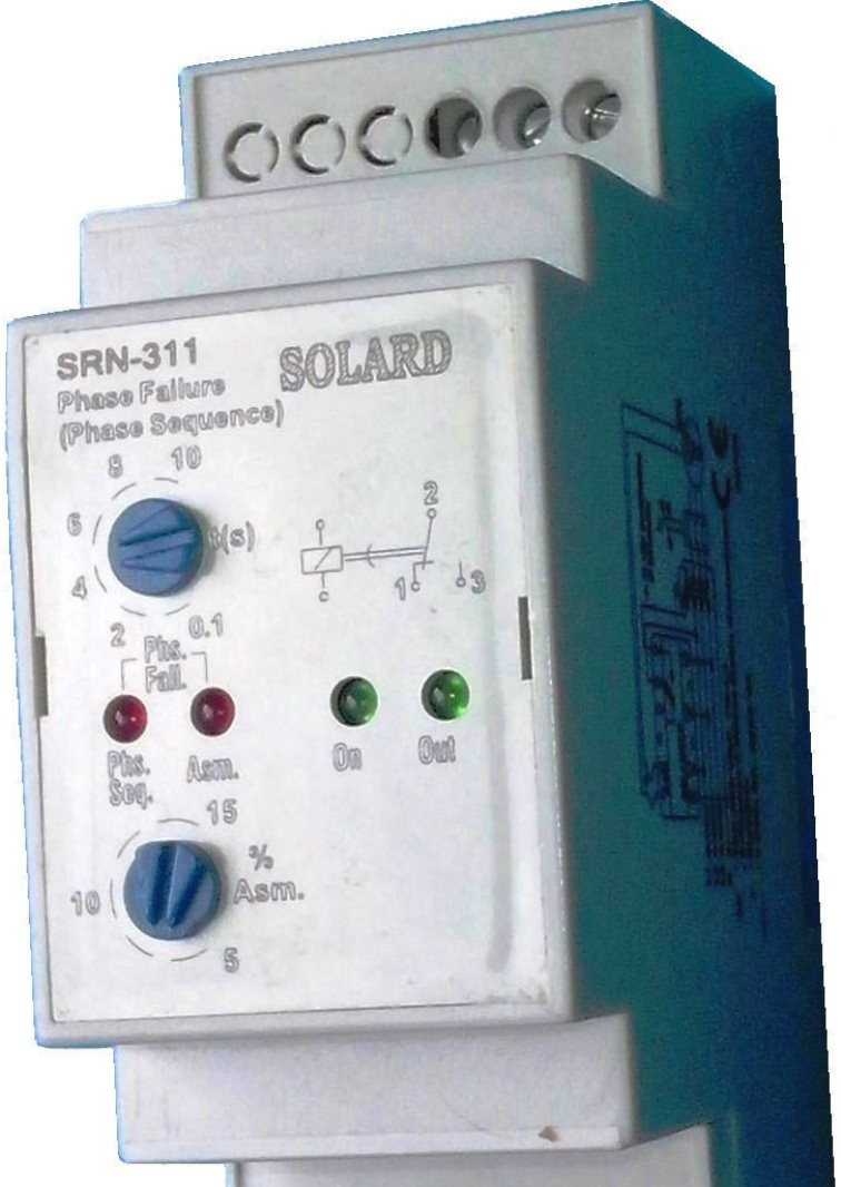
Elements of setting by microswitches: 1 - block of microswitches; 2, 3, 4 - options for setting operating voltages; 5, 6, 7, 8 - options for setting the asymmetry / symmetry functions
Among such advanced tuning elements, block microswitches are often found, located directly on the printed circuit board under the instrument case or in a special opening niche. By setting each of them in one position or another, the required configuration is created.


The setting usually comes down to setting the nominal protection values by rotating the potentiometers or the location of the microswitches.
For example, to monitor the state of contacts, the sensitivity level of the voltage difference (ΔU) is usually set to 0.5 V.
If it is necessary to control the load supply lines, the voltage difference sensitivity regulator (ΔU) is set to such a boundary position, where the point of transition from the working signal to the emergency signal is marked with a small tolerance towards the nominal value.
As a rule, all the nuances of setting up devices are clearly described in the accompanying documentation.
Marking of the phase control device
Classical devices are marked simply. A character-numeric sequence is applied on the front or side panel of the case, or the designation is noted in the passport.
A marking option for one of the most popular domestic devices. The designation is placed on the front panel, but there are also variations with placement on the sidewalls
So, a Russian-made device for connection without a neutral wire is marked:
EL-13M-15 AS400V
where: EL-13M-15 is the name of the series, AC400V is the allowable AC voltage.
Samples of imported products are labeled somewhat differently. For example, the "PAHA" series relay is marked with the following abbreviation:
PAHA B400 A A 3 C
The decryption is something like this:
- PAHA is the name of the series.
- B400 - standard voltage 400 V or connected from a transformer.
- A - adjustment by potentiometers and microswitches.
- A (E) - housing type for mounting on a DIN rail or in a special connector.
- 3 - case size in 35 mm.
- C - the end of the code marking.
On some models, one more value may be added before paragraph 2. For example, "400-1" or "400-2", and the sequence of the rest does not change.
This is how phase control devices are marked, endowed with an additional power interface for an external source. In the first case, the supply voltage is 10-100 V, in the second 100-1000 V.


