- Pumping station device
- Tank preparation and adjustment
- Situations that do not require adjustment
- Practical examples of relay settings
- Connecting a new device
- Pump stopped turning off
- Situations that do not require adjustment
- Primary indicators
- Air pressure in the accumulator.
- So what specific air pressure should be in the accumulator?
- Method for monitoring and adjusting air pressure in a hydraulic accumulator.
- Performance indicators
- Training
- Features of operation of pumping stations
- Causes of hardware problems
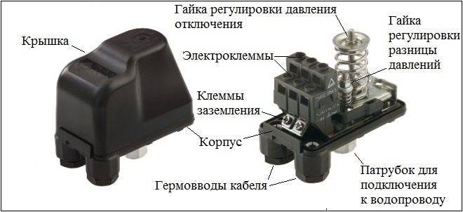
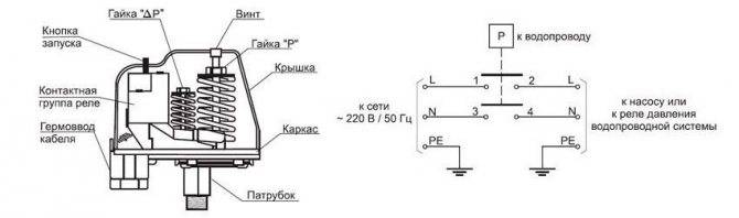
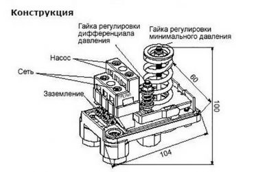
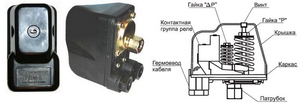
- How is the relay arranged?
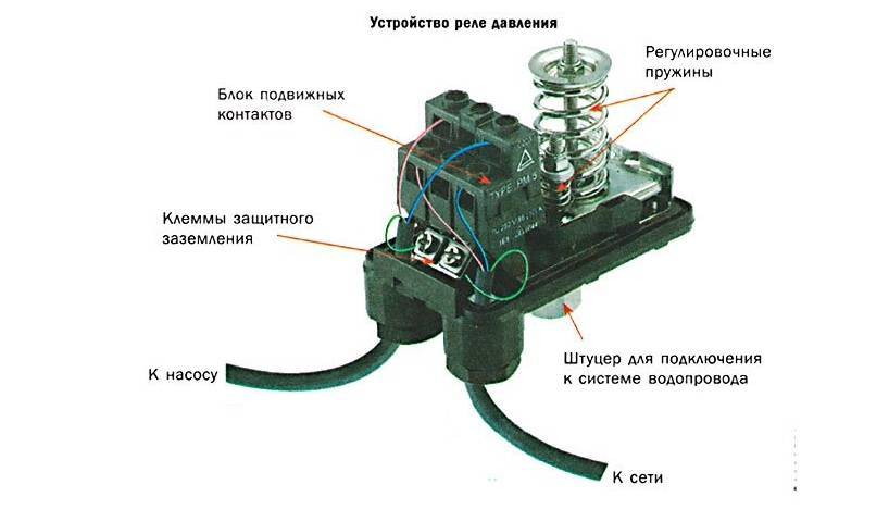
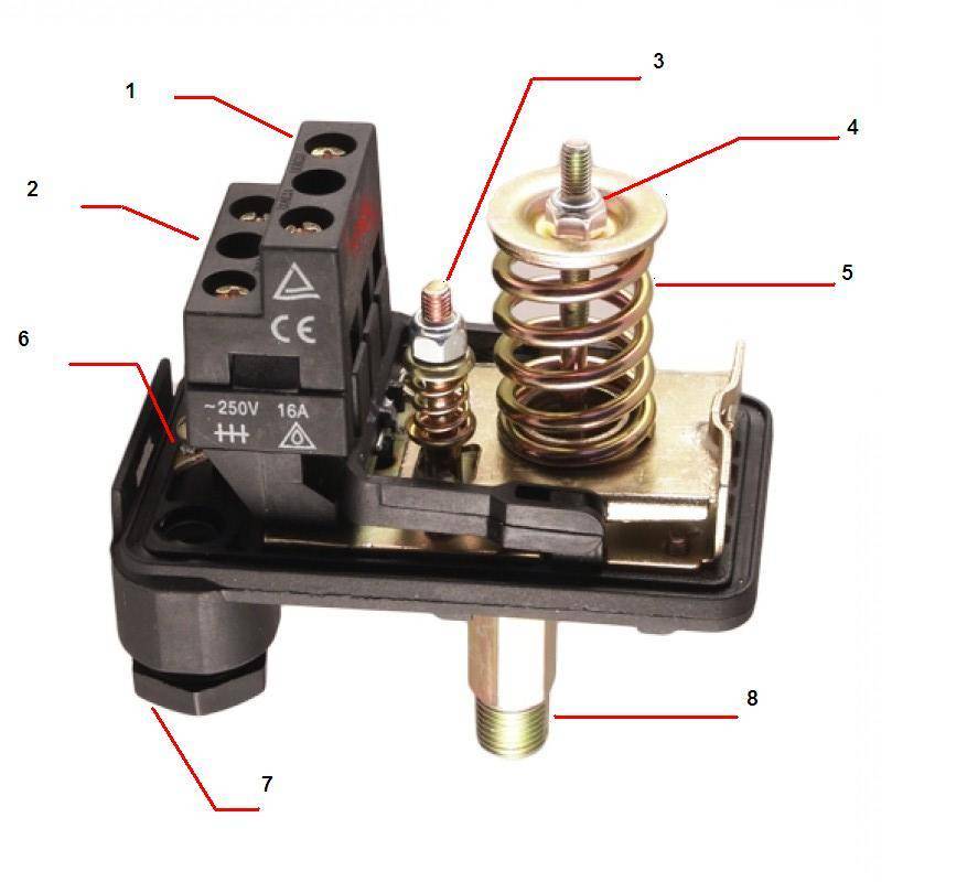
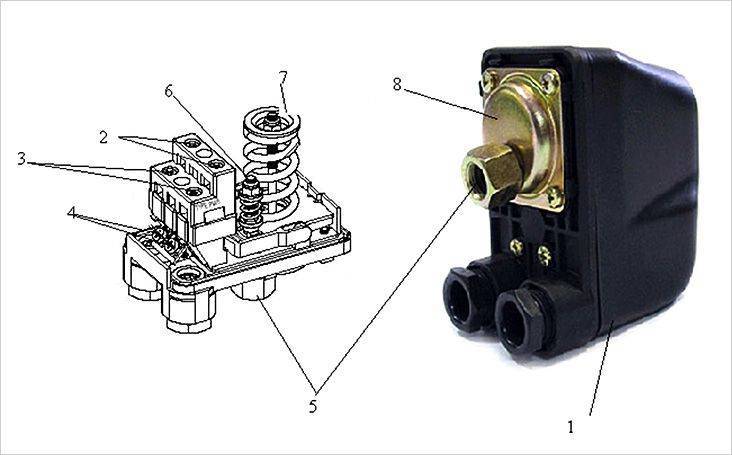
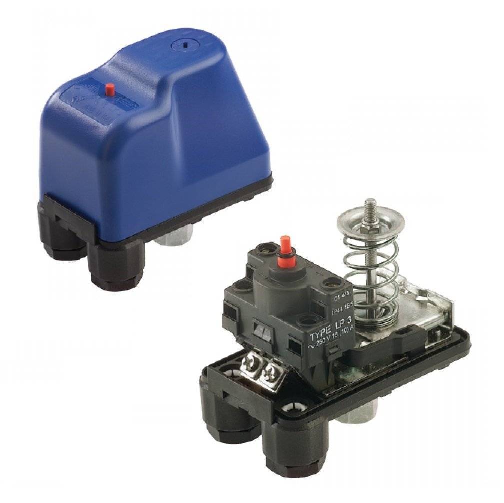
- The design and principle of operation of the pressure switch
- Preparation of the storage tank of the pumping station
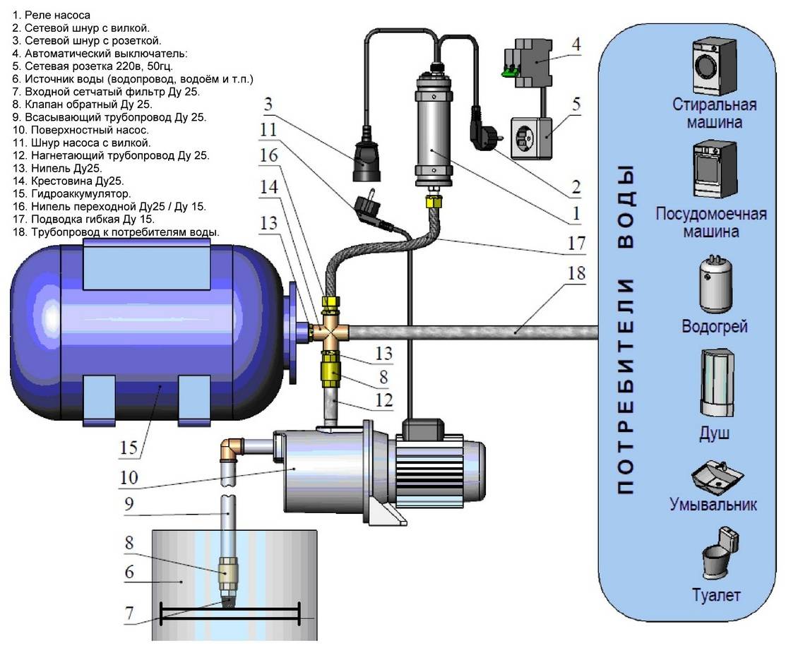
Pumping station device
In order to properly adjust this pumping equipment, you must have at least a minimal idea of how it works and on what principle it works. The main purpose of pumping stations consisting of several modules is to provide drinking water to all water intake points in the house. Also, these units are able to automatically increase and maintain the pressure in the system at the required level.
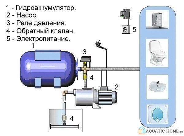
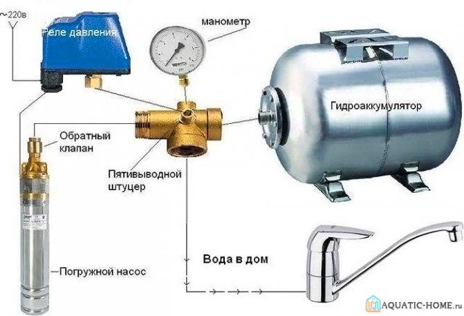
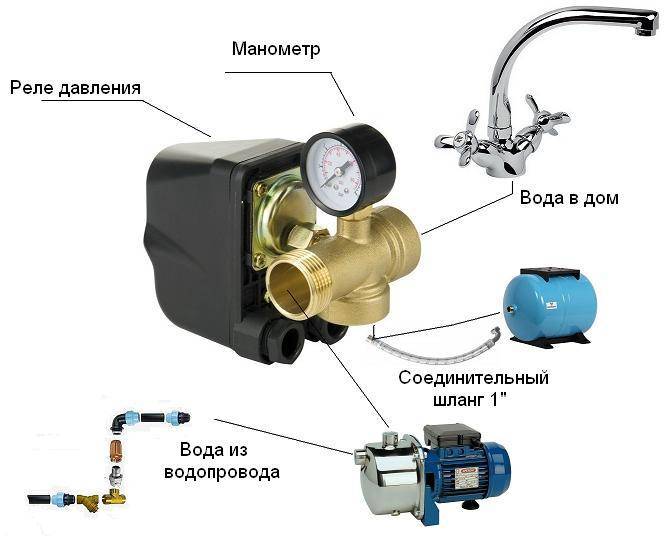
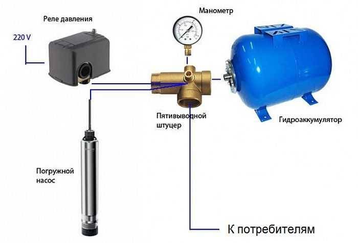
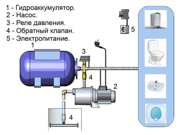
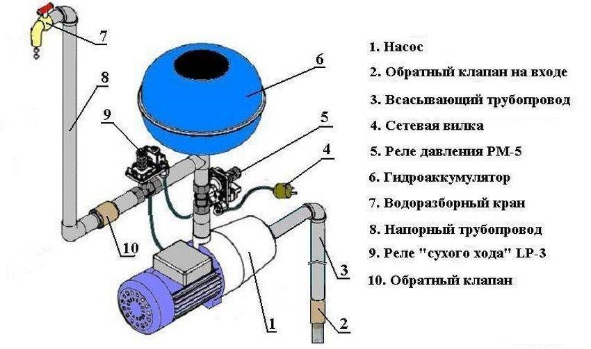
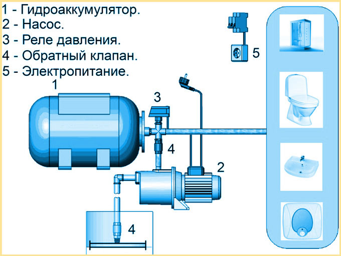
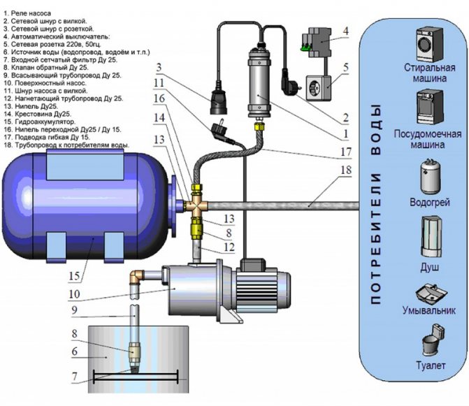
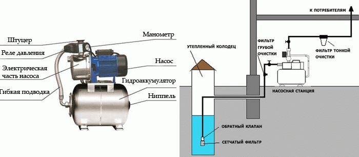
Below is a diagram of a pumping station with a hydraulic accumulator.
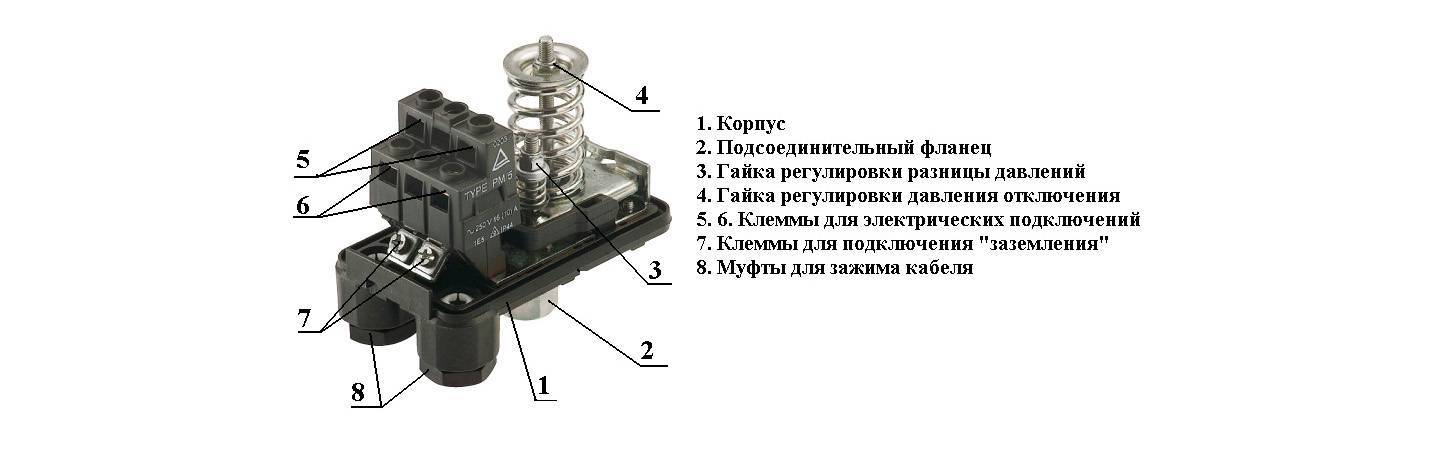
The pumping station includes the following elements (see the figure above).
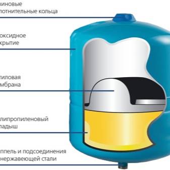
- Hydraulic accumulator.It is made in the form of a sealed tank, inside of which there is an elastic membrane. In some containers, a rubber bulb is installed instead of a membrane. Thanks to the membrane (pear), the hydraulic tank is divided into 2 compartments: for air and for water. The latter is pumped into a pear or into a part of the tank intended for liquid. The accumulator is connected in the section between the pump and the pipe leading to the water intake points.
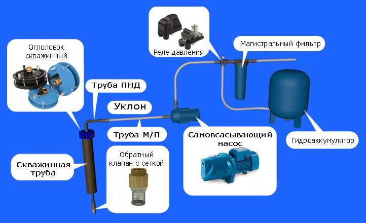
- Pump. It can be surface or borehole. The pump type must be either centrifugal or vortex. The vibration pump for the station cannot be used.
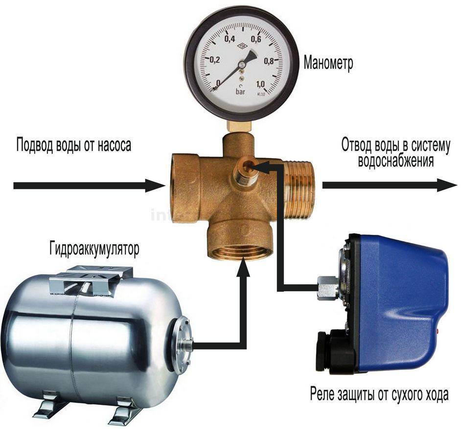
- Pressure switch. The pressure sensor automates the entire process by which water is supplied from the well to the expansion tank. The relay is responsible for turning the pump motor on and off when the required compression force is reached in the tank.
- Check valve. Prevents leakage of fluid from the accumulator when the pump is turned off.
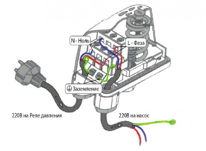
- Power supply. To connect the equipment to the electrical network, it is required to stretch a separate wiring with a cross section corresponding to the power of the unit. Also, a protection system in the form of automatic machines should be installed in the electrical circuit.
This equipment works according to the following principle. After opening the tap at the water intake point, water from the accumulator begins to flow into the system. At the same time, compression is reduced in the tank. When the compression force drops to the value set on the sensor, its contacts close and the pump motor starts to work. After the cessation of water consumption at the water intake point, or when the compression force in the accumulator rises to the required level, the relay is activated to turn off the pump.
Tank preparation and adjustment
Before the accumulators go on sale, air is pumped into them at a certain pressure at the factory. Air is pumped through the spool installed on this container.
Under what pressure is the air in the hydraulic tank, you can find out from the label glued to it. In the following figure, the red arrow indicates the line in which the air pressure in the accumulator is indicated.
Also, these measurements of the compression force in the tank can be made using an automobile pressure gauge. The measuring device is connected to the spool of the tank.
To start adjusting the compression force in the hydraulic tank, you need to prepare it:
- Disconnect the equipment from the mains.
- Open any faucet installed in the system and wait until the liquid stops flowing from it. Of course, it will be better if the crane is located near the drive or on the same floor with it.
- Next, measure the compression force in the container using a pressure gauge and note this value. For small volume drives, the indicator should be about 1.5 bar.
In order to properly adjust the accumulator, the rule should be taken into account: the pressure that triggers the relay to turn on the unit must exceed the compression force in the accumulator by 10%. For example, the pump relay turns on the motor at 1.6 bar. This means that it is necessary to create an appropriate air compression force in the drive, namely 1.4-1.5 bar. By the way, the coincidence with the factory settings is not accidental here.
If the sensor is configured to start the engine of the station with a compression force greater than 1.6 bar, then, accordingly, the settings of the drive change. You can increase the pressure in the latter, that is, pump up air, if you use a pump for inflating car tires.
Advice! Correction of the air compression force in the accumulator is recommended to be carried out at least once a year, since during the winter it can decrease by several tenths of a bar.
Situations that do not require adjustment
There can be many reasons when the pump does not turn off or does not turn on - from a blockage in communications to engine failure. Therefore, before starting to disassemble the relay, you should make sure that the rest of the equipment of the pumping station is working properly.
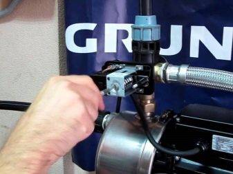
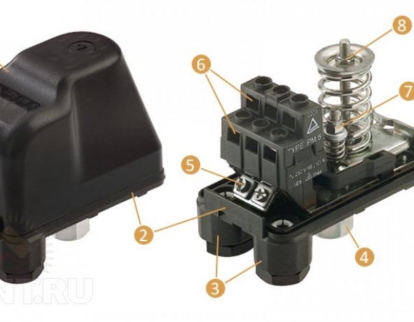
If everything is in order with the rest of the devices, the problem is in the automation. We turn to the inspection of the pressure switch. We disconnect it from the fitting and wires, remove the cover and check two critical points: a thin pipe for connecting to the system and a block of contacts.
To check if the hole is clean, it is necessary to dismantle the device for inspection, and if a blockage is found, clean it.
The quality of tap water is not ideal, so often the problem is solved by simply cleaning the inlet from rust and mineral deposits.
Even devices with a high degree of protection against moisture can fail due to the fact that the wire contacts are oxidized or burned.
If the cleaning measures did not help, and the adjustment of the position of the springs was also in vain, most likely the relay is not subject to further operation and should be replaced with a new one.
Suppose you got an old but working device in your hands. Its adjustment takes place in the same order as the setting of a new relay. Before starting work, make sure that the device is intact, disassemble it and check that all contacts and springs are in place.

Practical examples of relay settings
Let's analyze the cases when the appeal to the adjustment of the pressure switch is really necessary. This usually happens when buying a new appliance or when frequent pump shutdowns occur.
Also, setting will be required if you got a used device with downgraded parameters.
Connecting a new device
At this stage, you should check how correct the factory settings are and, if necessary, make some changes to the operation of the pump.
To track the progress of work, it is recommended to write down all the data received on a piece of paper. In the future, you can return the initial settings or change the settings again.
Pump stopped turning off
In this case, we forcibly turn off the pumping equipment and act in the following order:
- We turn on, and wait until the pressure reaches the maximum mark - suppose 3.7 atm.
- We turn off the equipment and lower the pressure by draining the water - for example, up to 3.1 atm.
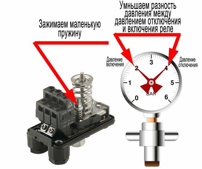
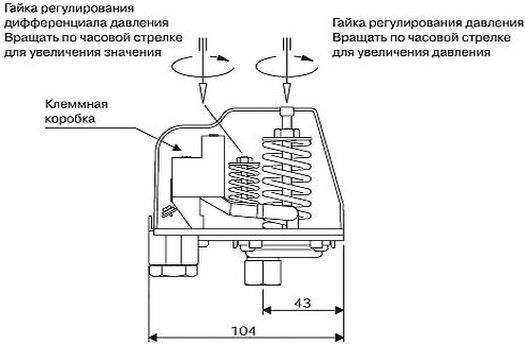
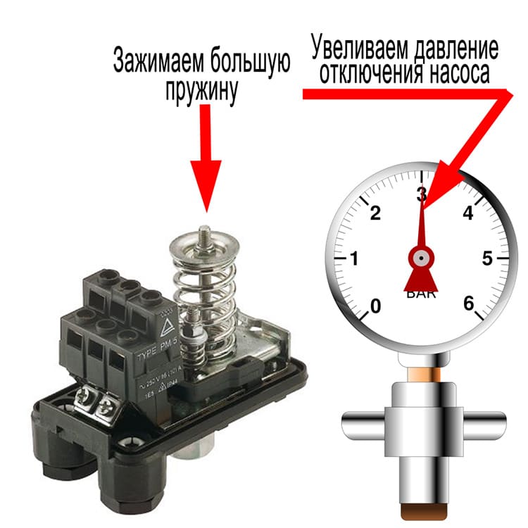
- Slightly tighten the nut on the small spring, increasing the value of the differential.
- We check how the cut-off pressure has changed and test the system.
- We adjust the best option by tightening and loosening the nuts on both springs.
If the cause was an incorrect initial setting, it can be solved without buying a new relay. It is recommended to regularly, once every 1-2 months, check the operation of the pressure switch and, if necessary, adjust the on / off limits.
Situations that do not require adjustment
There can be many reasons when the pump does not turn off or does not turn on - from a blockage in communications to engine failure. Therefore, before starting to disassemble the relay, you should make sure that the rest of the equipment of the pumping station is working properly.
If everything is in order with the rest of the devices, the problem is in the automation. We turn to the inspection of the pressure switch. We disconnect it from the fitting and wires, remove the cover and check two critical points: a thin pipe for connecting to the system and a block of contacts.
If the cleaning measures did not help, and the adjustment of the position of the springs was also in vain, most likely the relay is not subject to further operation and should be replaced with a new one.
Suppose you got an old but working device in your hands. Its adjustment takes place in the same order as the setting of a new relay. Before starting work, make sure that the device is intact, disassemble it and check that all contacts and springs are in place.
Primary indicators
The block is immediately hung on the pump. For a submersible pump, you need to choose it yourself. But in any case, the block is already adjusted during manufacture.
Many of them have the following start and stop settings: 1.5 - 3.0 atmospheres. But some models may have smaller values.
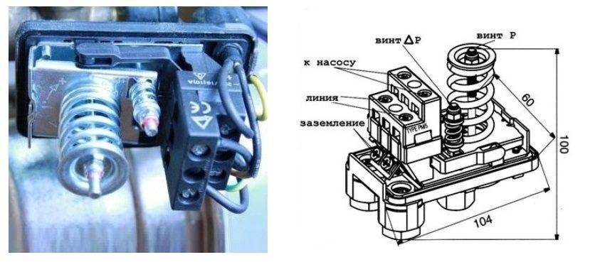
The lower start limit is at least 1.0 bar, the upper stop limit is 1.2 - 1.5 bar more. In the station manual, the lower start-up setting may be referred to as P, or PH.
This value may change. The difference between the lower and upper limits of operation can be referred to as ΔР (deltaР). This indicator is also regulated.
Air pressure in the accumulator.
Those who already have a good idea of the hydraulic accumulator device know that water is under pressure inside the membrane, and air is pumped outside the membrane.
The water pressure inside the membrane is created by the pump and only by the pump, and with the help of a pressure switch or automation units, the pressure range is set (Pvkl.and Рvkl.) in which the entire water supply system functions.
The maximum water pressure for which the accumulator is designed is indicated on its nameplate. As a rule, this pressure is 10 bar, which is quite sufficient for any domestic water supply system. The water pressure in the accumulator depends on the hydraulic characteristics of the pump and the system settings, but the air pressure between the membrane and the housing is a characteristic of the accumulator itself.
Factory air pressure:
Each accumulator comes from the factory pre-aired. As an example, we give the values of the factory air injection for hydraulic accumulators of the Italian company Aquasystem:
| Hydraulic accumulator volume: | Air pre-injection pressure: |
|---|---|
| 24-150 l | 1.5 bar |
| 200-500 l | 2 bar |
| The indicated values may differ from manufacturer to manufacturer. |
The actual pre-charge pressure is also indicated on the accumulator label (pre-charge pressure).
So what specific air pressure should be in the accumulator?
For water supply systems with a pressure switch:
The air pressure in the accumulator must be 10% lower than the start pressure of the pump.
Compliance with this requirement guarantees the presence of a minimum amount of water in the accumulator at the moment the pump is turned on, ensuring the continuity of the flow.
For example, if the pump starts at 1.6 bar, the accumulator air pressure should be around 1.4 bar. If the pump starts at 3 bar, the air pressure should be around 2.7 bar.
For water supply systems with a frequency converter:
The air pressure in the accumulator must be 30% lower than the constant pressure maintained by the frequency converter.
It turns out that the factory air injection pressure is not universal for all systems, because the pump on pressure can be adjusted individually by the user and the tank manufacturer cannot predict it. Therefore, the air pressure must be adjusted in each specific system in accordance with the above recommendations.
Method for monitoring and adjusting air pressure in a hydraulic accumulator.
You can control and pump up air pressure with a standard car pump or compressor by connecting it to a nipple, which is usually located under a plastic protective cap.
All measurements must be made in a system without water pressure. Those. the pump must be disconnected from the power supply, open the lowest tap and wait for the water to drain completely.
The larger the tank, the longer it takes to fill it up. For accumulators with a volume of 50 liters or more, we strongly recommend using a compressor.
When changing (increasing or decreasing) the pump activation pressure, do not forget to also change the air pressure in the accumulator. And do not confuse this procedure with setting the pressure switch.
Over time, the pressure in the air cavity of the accumulator may decrease, so it is recommended to check it regularly.
Air pressure monitoring intervals:
- If you use the water supply system only during the warm season, then it is recommended to check it before the start of each new season.
- If you use the water supply system year-round, then it is recommended to check it 2-3 times a year.
You can treat this simple procedure as a planned maintenance. maintenance, which quite realistically extend the life of the membrane.
If you notice any oddities in the operation of the water supply system, it makes sense to make an unscheduled control of the air pressure in the hydraulic tank, as well as the pressure on and off the pump (controlled by a water pressure gauge).
By the way, the stability of the air pressure in the accumulator over a long time is one of the important indicators of its quality.
Performance indicators
When performing a relay setting, certain characteristic names are used. They are well understood by a professional, but a person without experience can be confused. It is more correct to immediately understand their essence in order not to get confused during the execution of work.
Here are the main definitions of pressure:
- inclusion;
- shutdown;
- drop.
The cut-off pressure is usually referred to as "P-off". In some cases, this coefficient is also referred to as the upper pressure. This coefficient, as the name implies, indicates the pressure at which the station starts or restores work, and water begins to be pumped into the tank. As a rule, the manufacturer defaults to a lower pressure of 1.5 bar.
 The turn-on rate is also referred to as the lower pressure and is referred to as "Pvkl". This is the second coefficient, in the relay that came from the factory, as a rule, 3 bar is set or slightly less.
The differential is calculated as the difference between the lower and upper numbers. In a typical modification of the pressure switch before adjustment, this coefficient is usually approximately 1.5 bar.
The maximum, or rather, the maximum possible value of the shutdown indicator makes it possible to form an idea of the highest pressure in the system. The predominance of this feature can cause significant damage to the water supply and equipment. As a rule, this coefficient is approximately 5 bar or slightly less.
Training
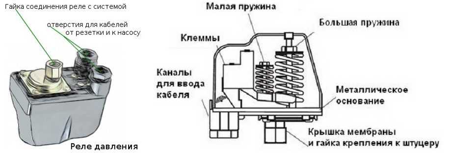
The relay should only be adjusted after checking the air pressure in the accumulator. To do this, you should better understand how this very hydraulic accumulator (hydraulic tank) works. It is a hermetically sealed container. The main working part of the container is a rubber pear into which water is drawn. The other part is the metal case of the accumulator. The space between the body and the pear is filled with pressurized air.
The pear in which water accumulates is connected to the water supply system. Due to the air in the hydraulic tank, the pear with water is compressed, which allows you to maintain the pressure in the system at a certain level. Thus, when a tap with water is opened, it moves through the pipeline under pressure, while the pump does not turn on.
Before checking the air pressure in the hydraulic tank, it is necessary to disconnect the pumping station from the network, and drain all the water from the hydraulic accumulator tank. Next, open the side cover on the tank, find the nipple and use a bicycle or car pump with a pressure gauge to measure the pressure. Well, if its value is about 1.5 atmospheres.
In the event that the result obtained is of a lower value, then the pressure is raised to the desired value using the same pump. It is worth recalling that the air in the tank must always be under pressure.
When using a pumping station, it is important to periodically check the air pressure in the hydraulic tank (about once a month or at least every three months), and if necessary, pump it up. These manipulations will allow the accumulator membrane to work longer.
But also, the tank should not be empty for too long without water, as this can lead to drying out of the walls.
After adjusting the pressure in the accumulator, it happens that the pumping station stops working in normal mode. This means that the pressure switch should be adjusted directly.
Features of operation of pumping stations
The operation of pumping equipment should be carried out in accordance with the instructions. Subject to all the rules, the equipment will last a long time, and the number of breakdowns will be minimal. The main thing is to eliminate any malfunctions in time.

From time to time, the pumping station should be serviced
Station operation features:
- Once every 30 days or after a break in work, the pressure in the accumulator should be checked.
- The filter will need to be cleaned. If this rule is not followed, water will begin to flow jerkily, pump performance will decrease significantly, and a dirty filter will lead to dry operation of the system, which will cause breakdowns. The frequency of cleaning depends on the amount of impurities in the water that comes from the well or well.
- The installation site of the station should be dry and warm.
- The system piping must be protected from freezing during the cold season. To do this, during installation, observe the desired depth. You can also insulate the pipeline or use an electrical cable that is mounted in trenches.
- If the station is not operated in winter, then the water from the pipes should be drained.
In the presence of automation, the operation of the station will not be difficult. The main thing is to change the filters in time and monitor the pressure in the system. Other nuances are taken into account at the installation stage.
Causes of hardware problems
The statistics of malfunctions in the operation of domestic pumping stations says that most often problems arise due to a violation of the integrity of the accumulator tank, pipeline, water or air leakage, and also due to various contaminants in the system. The need to intervene in its work may arise due to many reasons:
- Sand and various substances dissolved in water can cause corrosion, lead to malfunctions and reduce equipment performance. To prevent clogging of the device, it is necessary to use filters that purify the water.
- The decrease in air pressure in the station causes frequent operation of the pump and its premature wear. It is recommended to measure the air pressure from time to time and adjust it if necessary.
- The lack of tightness of the joints of the suction pipeline is the reason that the engine runs without turning off, but cannot pump liquid.
- Improper adjustment of the pressure of the pumping station can also cause inconvenience and even breakdowns in the system.
To extend the life of the station, it is recommended to periodically audit. Any adjustment work must begin with disconnecting from the mains and draining the water.

The power consumption and maximum head should be checked periodically.An increase in energy consumption indicates friction in the pump. If the pressure drops without leaks detected in the system, then the equipment is worn out
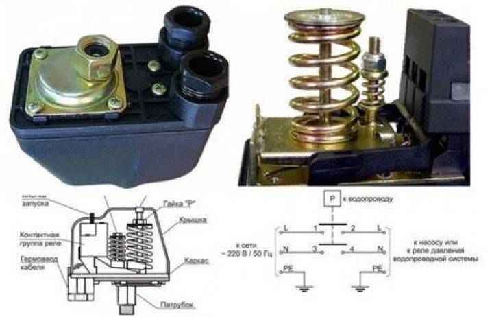
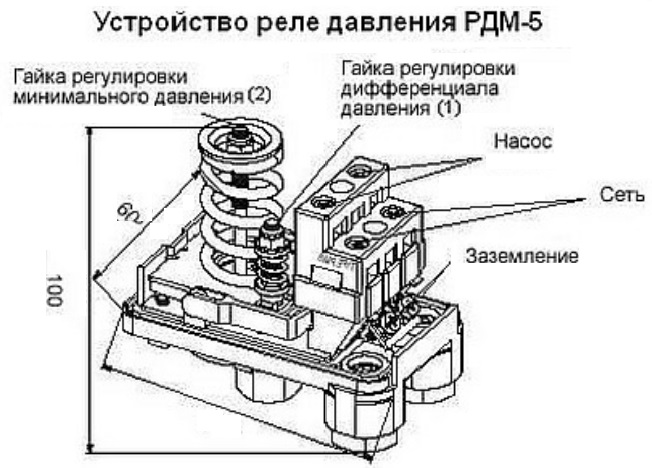
How is the relay arranged?
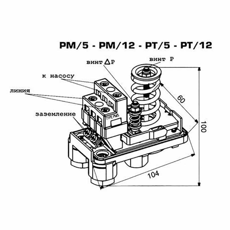
 For pumping stations intended for home use, the RM-5 pressure switch or its analogues is often used. It should be borne in mind that the device can be changed, and therefore the description given in this article will only be approximate and if problems arise, you will have to look for their cause either in the attached instructions or in the information on the World Wide Web.
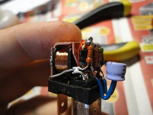
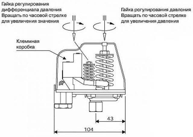
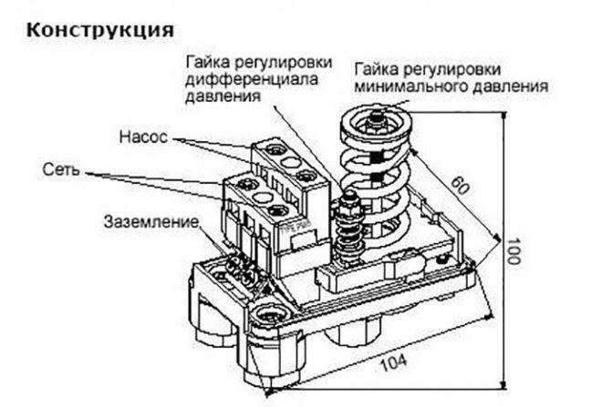
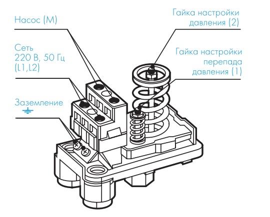
Each relay model PM-5 has a metal movable plate. Two springs exert pressure on it from opposite sides. In addition, a “pear” filled with water also presses on it. By turning the clamping nut on the appropriate spring, the actuation limits can be reduced or increased. Springs do not allow water to displace the spring, that is, the relay mechanism is designed in such a way that when displacement occurs, groups of electrical contacts are closed.
But to make it easier to understand, let's write a detailed algorithm of work:
- the pumping station pumps water into the reservoir. The engine turns on due to the closure of the contacts in the relay;
- the amount of water in the tank increases and when a certain value of the upper pressure is reached, the mechanism is triggered and the electrical circuit is broken, after which the pump is turned off. Water leakage is prevented by a non-return valve;
- as the water is consumed, the “pear” is emptied, the pressure in the system drops and the relay turns on again, closing the contacts.
The design and principle of operation of the pressure switch
The relay is a small block with maximum and minimum pressure springs.Its adjustment is carried out by means of the same springs that respond to changes in the pressure force. Having reached the minimum values, the spring weakens, and at the maximum, it compresses even more. Thus, it causes the relay contacts to open, and accordingly turns the pumping station on and off.
If there is water in the water supply, the relay allows you to create a constant pressure in the system and the required pressure. Proper adjustment ensures automatic operation of the pump, which can significantly extend its life.
But before proceeding to the setup, let's go through the device and the principle of operation of the pumping station.
It includes the following components:
- an electric pump that draws water from an external source. It can be submersible, permanently under water or outdoor;
- non-return valve that prevents water from leaving;
- pressure switch;
- water storage tank;
- piping system, which consists of various auxiliary components such as filters, pipes, etc.
As for the principle of operation, there is nothing complicated in this device. Inside the reservoir or tank there is a pear-shaped balloon made of modified food rubber, and air is pumped between it and the walls of the container. The pump fills the "pear" with water, because of which it expands and compresses the outer air layer, which begins to put pressure on the wall. By adjusting the relay, the owner of the pumping station can set the tank filling limit and the moment it is turned off. All this is controlled by a manometer.
To prevent water from going back into the well or into the system, a spring-loaded valve is provided in the pump.It is enough just to open it and the water that has collected in the "pear" will go through the system. The pressure will drop as the water is consumed, and after it drops below the threshold set in the relay, the pumping station will automatically turn on and fill the tank with water.
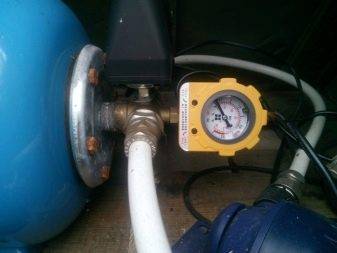
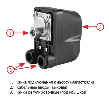
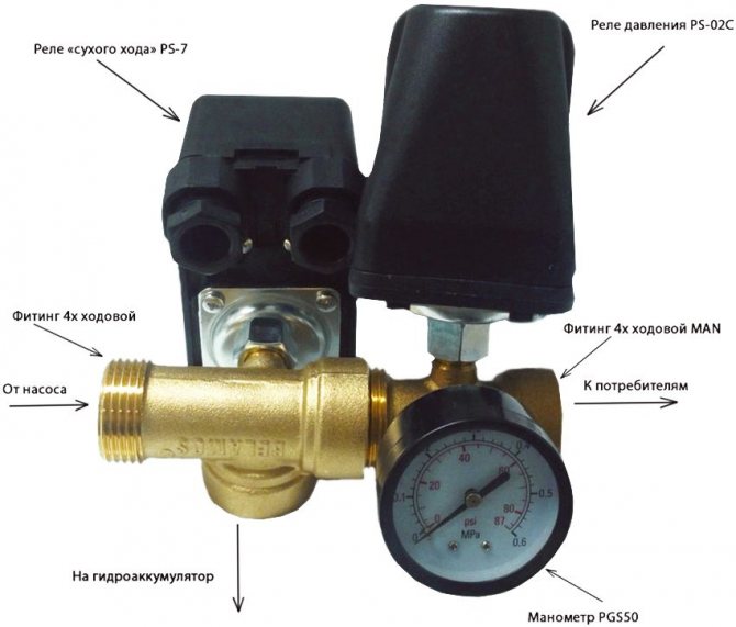
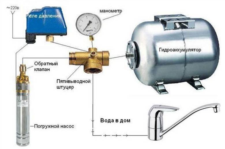
The relay is connected between the outlet of the tank and the check valve on the pipeline. In order to save money, all splitters are usually assembled from separate components, but in fact it is easier to buy a five-way fitting, where threads are provided for all parts, including a pressure gauge
In this case, it is extremely important not to confuse the inlets for the check valve and the fitting, since the pump setting will be impossible in this case. But the use of standard spare parts allows you to minimize such errors.
Preparation of the storage tank of the pumping station
Before adjusting the pressure switch itself, it is necessary to prepare the accumulator. It consists of a sealed container and a rubber pear that divides this tank into two parts inside. When pumping water into the first pump, air pressure rises in the second. Then this air mass, with its pressure on the pear, will maintain the pressure in the water supply pipe.
Hydraulic accumulator (storage tank)
In order for the pumping station to work in the optimal mode, it is necessary to correctly select the air pressure for the accumulator. If you make it too high or too low, then the hydraulic pump will start up too often. This setting is a direct path to rapid equipment wear.
The required air pressure in the accumulator is set after it is completely empty of water.After its descent, air is pumped at the rate of 1.4–1.7 atmospheres for a tank of 20–25 liters and 1.7–1.9 atmospheres with a larger volume. Specific values should be viewed in the technical passport of the station.


