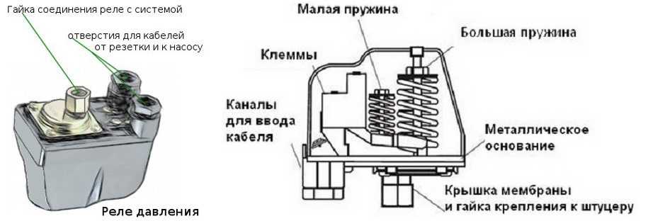
- DIY pressure switch
- Work order
- Station adjustment
- Shutter types
- A few tips and tricks
- Technical specifications
- Astatic
- Static
- Isodromny
- Purpose
- Air compressor from car parts
- Relay setting
- Lower pressure threshold
- Upper pressure threshold
- Plumbing in the house
- Briefly about the main
- Adjustment and commissioning process
- DIY pressure switch
- Types of pressure switches
- Conclusion
DIY pressure switch
If you have a working thermostat from an old refrigerator at home, as well as some work skills, then you can safely make a pressure switch for a compressor with your own hands. However, it is worth warning in advance that such a solution cannot differ in great practical possibilities, since the upper pressure with such an approach will be limited only by the strength of the rubber bellows.
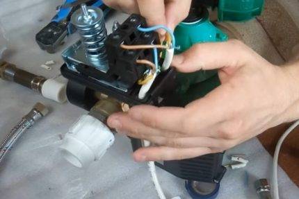
Work order
After opening the cover, the location of the required group of contacts is found out, for this purpose the circuit is called. The first step is to refine the connection of the compressor with the thermal relay: the contact groups are connected to the terminals of the electric motor circuit, and the unloading valve is connected to the outlet pipe with a control pressure gauge. The adjusting screw is located under the thermostat cover.
When the compressor is started, the screw rotates smoothly, at the same time, you need to monitor the readings of the pressure gauge. It is worth taking care that the receiver is filled by 10-15 percent! To achieve the minimum pressure, it is necessary to smoothly move the stem of the face button. To this end, the cover is placed in its original place, after which the adjustment is performed almost blindly, since there is nowhere to install the second pressure gauge.
For safety reasons, it is not recommended to set the thermostat pressure beyond 1-6 atm! If devices with a stronger bellows are used, the maximum range can be raised to 8-10 atm, which is usually enough for most tasks.
The capillary tube is cut off only after you make sure that the relay is working. After the release of the refrigerant inside, the end of the tube is placed inside the unloading valve and soldered.
The next step is a homemade pressure switch for the compressor is connected to the control circuit. To do this, the relay is fixed to the control board with a nut. The locknut is screwed onto the threads on the stem, thanks to which the air pressure can be adjusted in the future.
Taking into account the fact that the contact group of the thermal relay from any refrigerator is designed to work with high currents, they can switch quite powerful circuits, for example, secondary circuits when working with a compressor engine
Station adjustment
Summarizing all the main stages, we can say that the compressor setting must necessarily include the following operations:
- Checking the integrity and reliability of electrical and air connections, monitoring the compliance of the level of lubricating fluids, the integrity and serviceability of the drive, monitoring the direction of rotation of the compressor unit;
- Start-up of the station, during which the condition and serviceability of the valves are assessed;
- Evaluation and verification of the operability of the installation without load;
- Checking the serviceability of automatic emergency shutdown systems;
- Temperature control in the block;
- Troubleshooting and their elimination;
- Directly adjust the pressure produced by the compressor.
Please note: the last point cannot be trusted to an unprepared worker. Direct pressure adjustment should only be carried out by experienced trained personnel.
During adjustment:

- Measurements of the real maximum and minimum pressure are carried out;
- With the help of a sensor, the adjustments change in the right direction;
- The working range (medium pressure) is shifted;
- After turning on the compressor, the first setting point is repeated;
- If necessary, an additional adjustment of the maximum, minimum and average values is made.
Shutter types
 An important body of 220 V throttle bodies are single-seat, valve, diaphragm, disk, double-seat valves, pinch valves with rigid or elastic seals. With a decrease in the tightness of unloaded valves of industrial systems, the repair of a 380 V valve is carried out by a mechanical workshop after a preliminary diagnosis of all parts and mechanisms.
Prevention of control devices is carried out in accordance with the plan approved by the manufacturer of the product and the standards for the gas control unit.The limiting values of adjustment are determined by the technological conditions and the specifics of the operating organization.
Each device has a serial number, a passport, a certificate of conformity to the state standard. All planned manipulations or repair work are displayed in the GRU operational log.


A few tips and tricks
For the normal functioning of the pumping station, it is recommended to measure the air pressure in the accumulator every three months. This measure will help maintain stable settings in the operation of the equipment. A sharp change in indicators may indicate some kind of breakdown that needs to be fixed.
In order to quickly monitor the status of the system, it makes sense to simply record the readings of the water pressure gauge from time to time when turning the pump on and off. If they correspond to the numbers set when setting up the equipment, the system can be considered normal.
A noticeable difference indicates that it is necessary to check the air pressure in the hydraulic tank and, possibly, reconfigure the pressure switch. Sometimes you just need to pump some air into the accumulator, and the performance will return to normal.
The accuracy of the pressure gauge has a certain error. This may be partly due to the friction of its moving parts during measurements. To improve the process of readings, it is recommended to additionally lubricate the pressure gauge before starting measurements.
The pressure switch, like other mechanisms, tends to wear out over time. Initially, you should choose a durable product. An important factor in the long-term operation of the pressure switch is the correct settings.do not use this instrument at the maximum allowable upper pressures.
If there are problems and inaccuracies in the operation of the pressure switch, it may need to be disassembled and cleaned of contaminants
A small margin should be left, then the elements of the device will not wear out so quickly. If it is necessary to set the upper pressure in the system at a sufficiently high level, for example, at five atmospheres, it is better to purchase a relay with a maximum allowable operating value of six atmospheres. Finding such a model is more difficult, but it is quite possible.
The presence of contaminants in the water pipes can lead to serious damage to the pressure switch. This is a typical situation for old water pipes made of metal structures.
Before installing the pumping station, it is recommended to thoroughly clean the water supply. It will not hurt to completely replace metal pipes with plastic structures, if possible.
When adjusting the relay, the adjusting springs should be treated with extreme care. If they are compressed too much, i.e. twisted during the setup process, errors will very soon begin to be observed during operation of the device. Relay failure in the near future is almost guaranteed.
If during the check of the operation of the pumping station a gradual increase in the shutdown pressure is observed, this may indicate that the device is clogged. You don't need to change it right away.
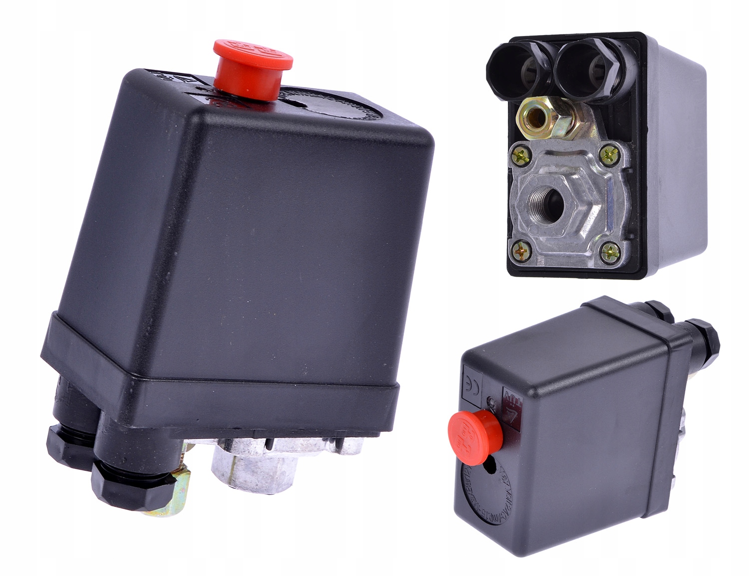
It is necessary to unscrew the four mounting bolts on the pressure switch housing, remove the membrane assembly and thoroughly flush the inside of the switch, where possible, as well as all small openings.
Sometimes it is enough just to remove the relay and clean its holes from the outside without disassembly. It also does not hurt to clean the entire pumping station. If water suddenly begins to flow directly from the relay housing, it means that particles of pollution have broken through the membrane. In this case, the device will have to be completely replaced.
Technical specifications
 The technical parameters of the control device are designed to visualize the indicators of the maximum and minimum gas pressure, as well as the flow rate of the working medium. The highest value at the inlet/outlet for a liquefied medium is 250 atm, for liquefied fuel - 25 atm. At the output, the indicator varies within 1–16 atm.
In the design, the electric gas pressure regulator 220 V contains a sensitive mechanism that can compare the signal from the setpoint with the current value, converts the command pulse into mechanical work to move the movable plate to the neutral position. In the event that the switching force is exceeded, the sensing element, or the pilot, sends a command to switch off to the sensors.
The pilot regulator can be astatic, static, isodromic.
Astatic
During operation, an astatic type relay experiences two types of load: active (acting) and passive (opposing). It is recommended to connect a device with a sensitive membrane to the equipment for sampling gas from the central pipeline. A device of this type adjusts the pressure of the system medium according to the given indicators, regardless of the degree of workload on the control element.


Static
The static pressure switch design kit includes process stabilizers that provide resistance to friction and backlash on the joints of the system.Static devices form equilibrium indicators that differ from the allowable values of the rated load. The control process is switched on by the acting force along the damped amplitude.
Isodromny
Automatic activation of the isodromic industrial relay is performed when the pressure deviates from the set value. The 380 V pilot body responds to real pressure gauge readings that differ from the permissible norm. To unload the pressure, the regulating element independently reduces the performance to the optimum operating parameter.
Purpose
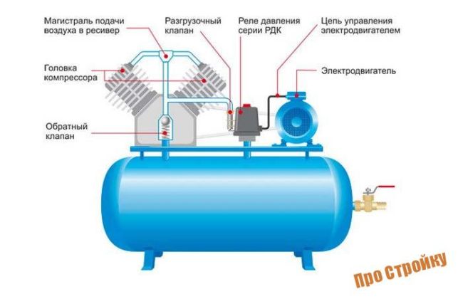
After starting the compressor engine, the pressure in the receiver begins to rise.
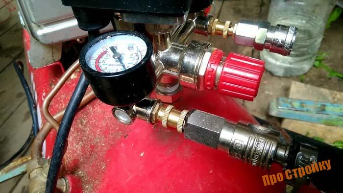
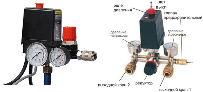
If the slider of the excitation rheostat R is moved, then a resistor will be introduced into the SHOV winding circuit. The presence of a free connector allows you to install a control pressure gauge in a place convenient for the user. Controlling the pressure on the pressure gauge, set the required values.
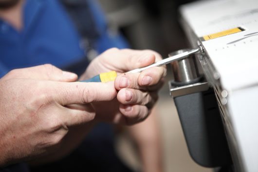
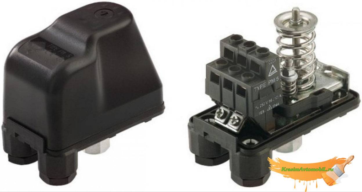
Other names are telepressostat and pressure switch. To do this, you will have to: Disconnect the wiring from the contacts; Have a bite to eat the motor tubes connecting it to other parts; Image 4 - biting the motor tube Unscrew the fixing bolts and remove from the casing; Disconnect the relay by unscrewing the screws; Image 5 - disconnecting the relay Next, you need to measure the resistance between the contacts; By attaching the tester probes to the output contacts, normally you should get OM, depending on the model of the engine and refrigerator. The working system consists of springs of different stiffness levels that respond to pressure changes.
There may also be other auxiliary mechanisms that require activation: a safety or unloading valve.Types of pressostatic devices There are only two variations in the execution of the compressor unit of automation. With the help of a relay, it becomes possible to automatically work while maintaining the required level of compression in the receiver.
Recommended: How to fix overhead wiring
Air compressor from car parts
It is the largest supplier in the CIS. Scheme of automated control of the electric compressor The second contact PB1 turns on the alarm relay P2 after 15 seconds, its closed contact can trigger an alarm, but by this time the pump attached to the compressor has time to create the necessary pressure in the lubrication system, and the RDM oil pressure switch opens, breaking alarm circuit. Electric drive control circuit of the fire-ballast pump When power is applied to the circuit, even before the engine starts, the electromagnetic time relays RU1, RU2, RU3 of the acceleration relay are activated. This indicator must be less than the nominal pressure of the air blower.
Usually the difference value is set to 1 bar. If the relay fails, and the compression level in the receiver rises to critical values, then the safety valve will operate to avoid an accident, relieving air.
Restarting with the KNP button is possible when the contact Rv is closed in its circuit, which corresponds to the position of the Rv slider on the right. The operating system is spring mechanisms with varying degrees of rigidity, reproducing the response to fluctuations in the air pressure unit.
If the pressure switch was found to be the object of a malfunction, the professional will insist on replacing the device. In addition, there will be a significant pressure drop in the system.A control pressure gauge is installed if it is not necessary, then the threaded inlet is also plugged.
Compressor cannot rev up REPAIR bad start FORTE VFL-50
Relay setting
The manufacturer provides the setting of pumping stations for average indicators:
- lower level - 1.5-1.8 bar;
- upper level - 2.4-3 bar.
Lower pressure threshold
If the consumer is not satisfied with such values, then knowing how to adjust the pressure in the pumping station, they can be changed. Having dealt with the installation of the correct pressure in the storage tank, proceed to adjust the sensor settings:
- The pump and relay are de-energized. All liquid is drained from the system. The pressure gauge is at zero at this point.
- The plastic cover of the sensor is removed with a screwdriver.
- Turn on the pump and record the pressure gauge readings at the moment the equipment is turned off. This indicator is the upper pressure of the system.
- The tap farthest from the unit opens. The water gradually drains, the pump turns on again. At this point, the lower pressure is determined by the pressure gauge. The pressure difference to which the equipment is currently set is calculated mathematically - subtracting the results obtained.
Having the opportunity to evaluate the pressure from the tap, select the required setting. Adjustment for increasing the pressure of the pumping station is carried out by tightening the nut on a large spring. If the pressure needs to be reduced, the nut is loosened. Do not forget that adjustment work is carried out after disconnecting the device from the power supply.
Upper pressure threshold
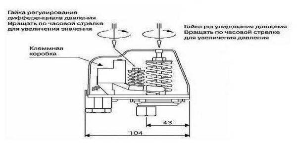
To set the optimal frequency of switching on the pump, it is necessary to adjust the pressure difference. A small spring is responsible for this parameter. The optimal value of the difference between the upper and lower pressure thresholds is 1.4 atm. If it is necessary to increase the upper limit at which the unit turns off, then the nut on the small spring is turned clockwise. When decreasing - in the opposite direction.
What effect does this adjustment have on the equipment? An indicator below the average (1.4 atm.) Will provide a uniform supply of water, but the unit will often turn on and quickly break down. Exceeding the optimal value contributes to a gentle use of the pump, but the water supply will suffer due to noticeable pressure surges
Adjustment of the pressure difference of the pumping station is carried out smoothly and carefully. The impact needs to be verified. The scheme of actions performed when setting the lower pressure level is repeated:
The scheme of actions performed when setting the lower pressure level is repeated:
- All appliances are disconnected from the mains.
- Water is drained from the system.
- The pumping equipment is turned on and the result of the adjustment is evaluated. In case of unsatisfactory performance, the procedure is repeated.
When making pressure difference adjustments, there are limitations that must be taken into account:
- Relay parameters. You can not set the upper pressure threshold equal to 80% of the maximum value of the device. Data on the pressure for which the controller is designed is present in the documents. Household models usually withstand up to 5 atm. If it is necessary to raise the pressure in the system above this level, it is worth buying a more powerful relay.
- Pump characteristics.Before choosing an adjustment, you must check the characteristics of the equipment. The unit must turn off at a pressure that is 0.2 atm. below its upper limit. In this case, it will function without overloads.
Plumbing in the house
When using a personal water supply in the house, it may happen that the pump providing water pumping is constantly activated and deactivated. And although the RD should be responsible for this, the malfunction lies not in it.


If the pressure in the system rises sharply, turning off the pump, and then drops sharply, turning on the pump, then the accumulator is faulty, in which the membrane responsible for compensating for the increased pressure is either torn or greatly stretched.
Solving the problem is simple: you need to purchase a new membrane and install it. You can do it yourself.

Hydraulic accumulator with membrane inside
In order for the pump to work properly, it is necessary to maintain the pressure in the water tank, which forms the pressure in the relay, approximately 10% below the switching level.
Another common problem is the constant operation of the pump even in the absence of water in the system. There are several reasons for this:
- wiring failure;
- terminal oxidation;
- motor malfunction.
To identify the problem, you need to take a multimeter and ring the devices. Defective devices should be replaced.
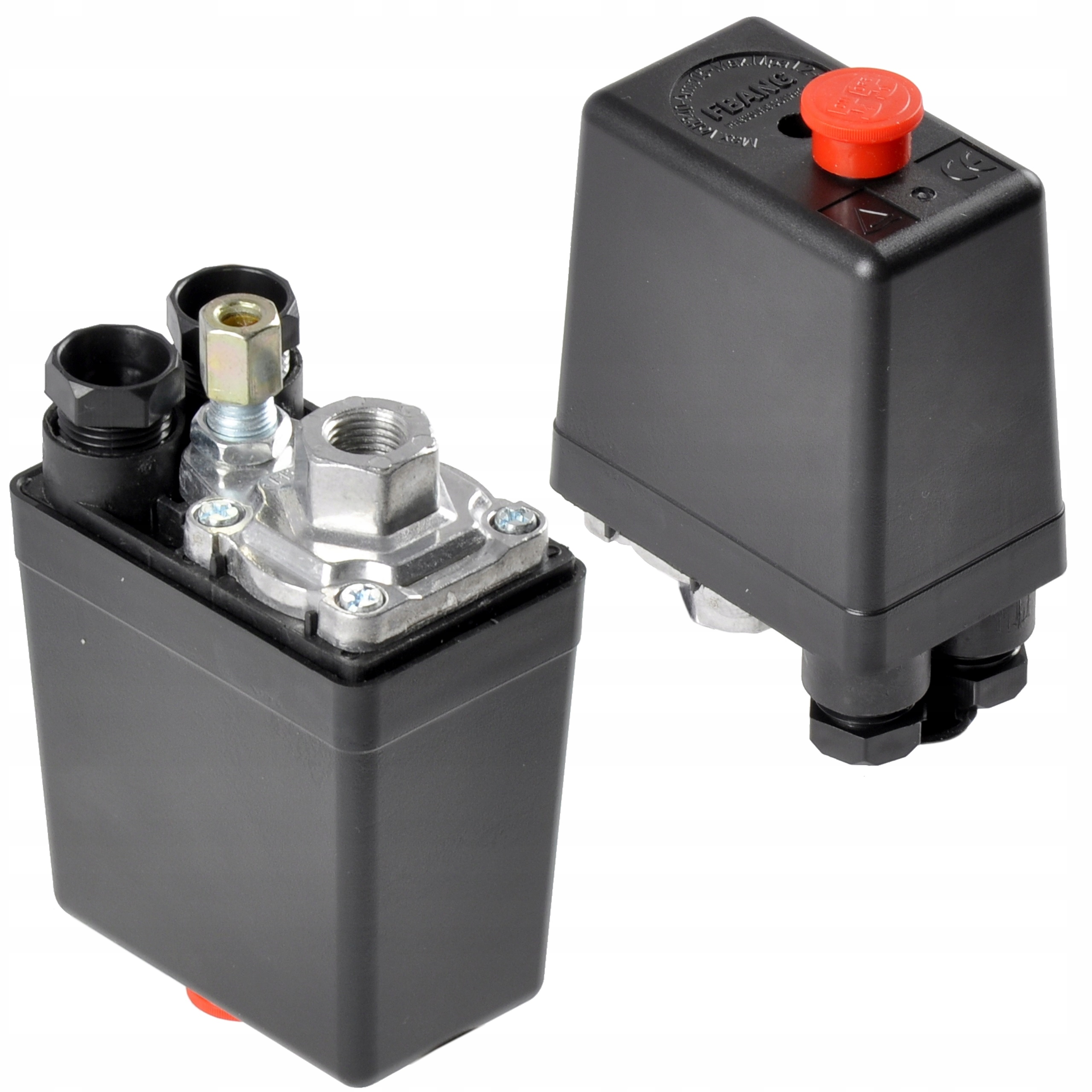
If it is known for sure that the pressure switch for the pumping station is faulty, then the device should be replaced as follows:
- Disconnect the RD from power.
- Drain the water from the accumulator.
- Open taps.
- Disconnect contact wires and ground.
- Remove the old RD from the pump pipe (due to residual pressure, water may flow from the fitting, so it is better to put some kind of container under the pump).
- Connect the new RD to the fitting and connect it to the power supply.
Particular attention should be paid to gaskets at the points of contact. If they are of poor quality or they are installed incorrectly, a leak will appear.. When the new RD is installed, you can turn off the water tap, turn on the pump and make adjustments.
Once the new RD is in place, you can turn off the water tap, turn on the pump, and complete the setup.
About pressure switch malfunctions in this video:
Briefly about the main
RD - a device that regulates the maximum and minimum switching thresholds, which are responsible for activating the pump for forced pumping of water.
RD are mechanical and electronic. The latter are 2-3 times more expensive and have a number of advantages over mechanical counterparts. In particular, electronic relays are easier and more convenient to set up, and they also have higher accuracy. Although the principle of operation of both types of RD is the same.
Adjustment of the RD is carried out in accordance with the purposes for which the water supply in the house will be used. To take a bath, it is enough to maintain a low pressure level in the plumbing system. To operate a hot tub or hydromassage, you will need to maintain a high average pressure.
Adjustment and commissioning process
Factory set parameters do not always meet the requirements of the consumer. In most cases, this is due to insufficient compression force at the highest point of parsing.
Also, the operating range of the pressure switch may not be suitable. In this case, self-adjustment of the actuator will be relevant.
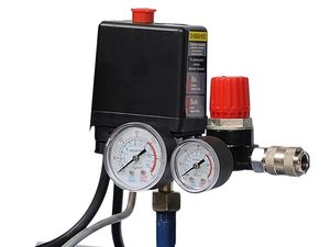
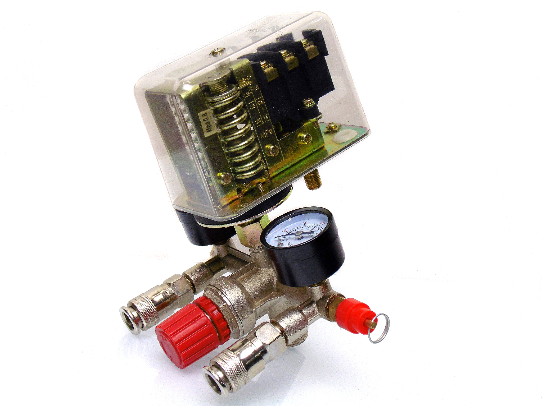
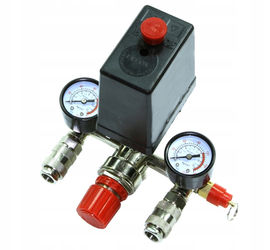
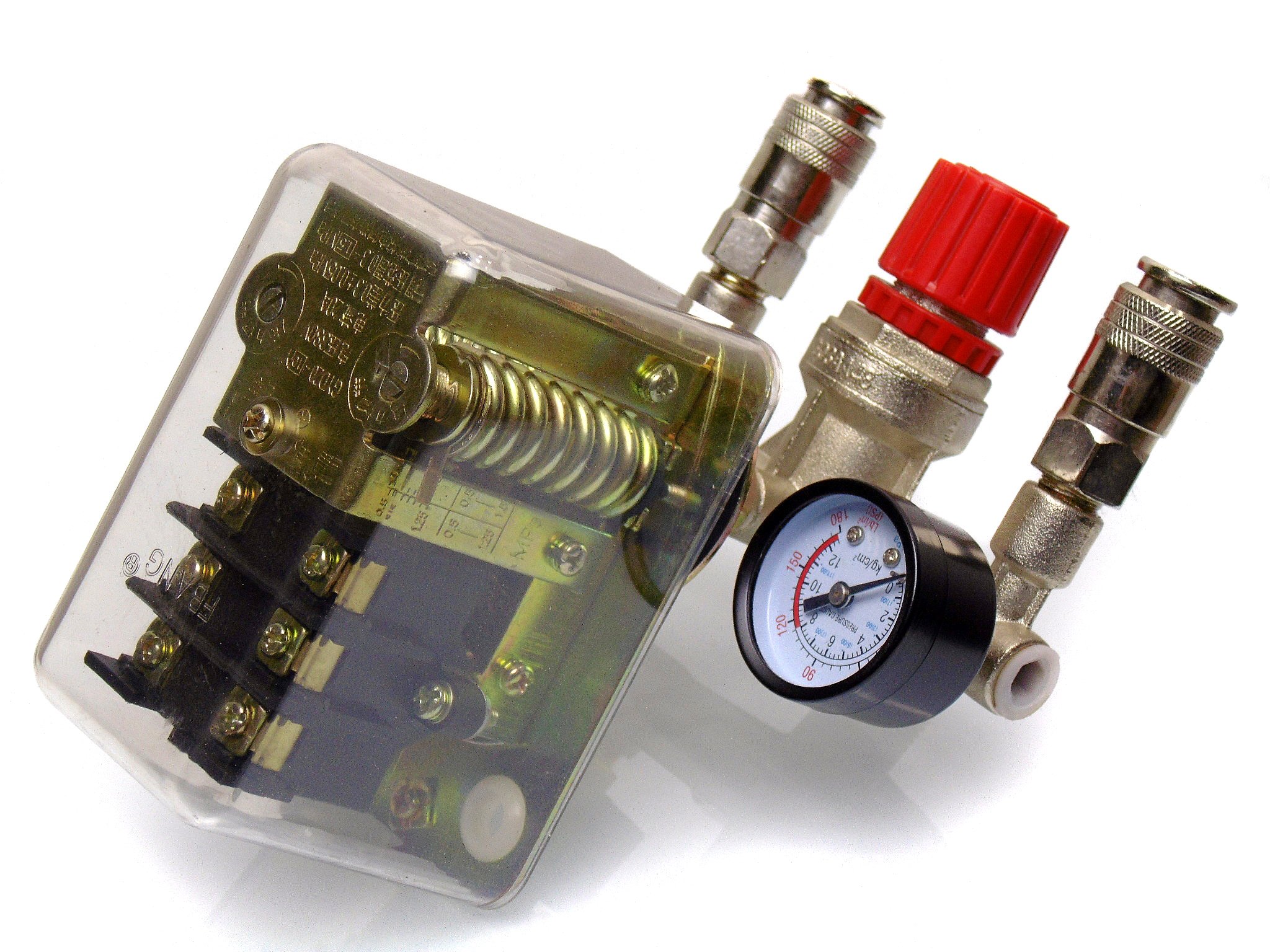
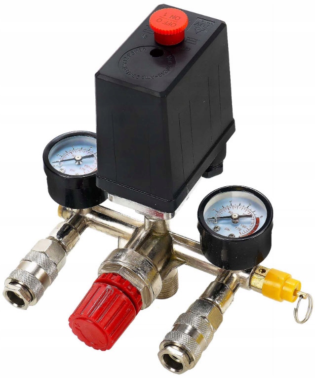
Standard factory settings: upper limit 2.8 atmospheres, lower 1.4 bar. The parameters are controlled visually by means of a pressure gauge included in the standard set of the pressure switch. Newer models, such as Italtecnica, have a transparent housing and are equipped with a compression gauge directly on the relay.
To start setting the working compression value, you will need to examine the engraved plate, which indicates the parameters of the electric motor and compressor.
We only need the largest value that the fixture produces. This indicator indicates the maximum pressure force that can be set on the relay for the correct operation of the entire pneumatic system.


If you set the specified value (in the figure 4.2 atm), then taking into account all the factors - drops in the power supply, the development of the service life of parts, and more - the compressor may not reach the maximum pressure, and accordingly it will not turn off.
In this mode, the working elements of the equipment will begin to overheat, then deform and eventually melt.
The maximum value of the ejector must be taken into account when determining the maximum value of the relay. This figure must be less than the nominal pressure of the compressor. In this case, all elements of the system will work in uninterrupted mode.
For reliable operation without shutdowns, it is required to set the highest shutdown pressure on the relay that does not reach the nominal value engraved on the compressor, namely, lower by 0.4-0.5 atm. According to our example - 3.7-3.8 atm.
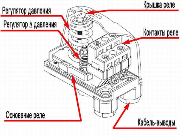
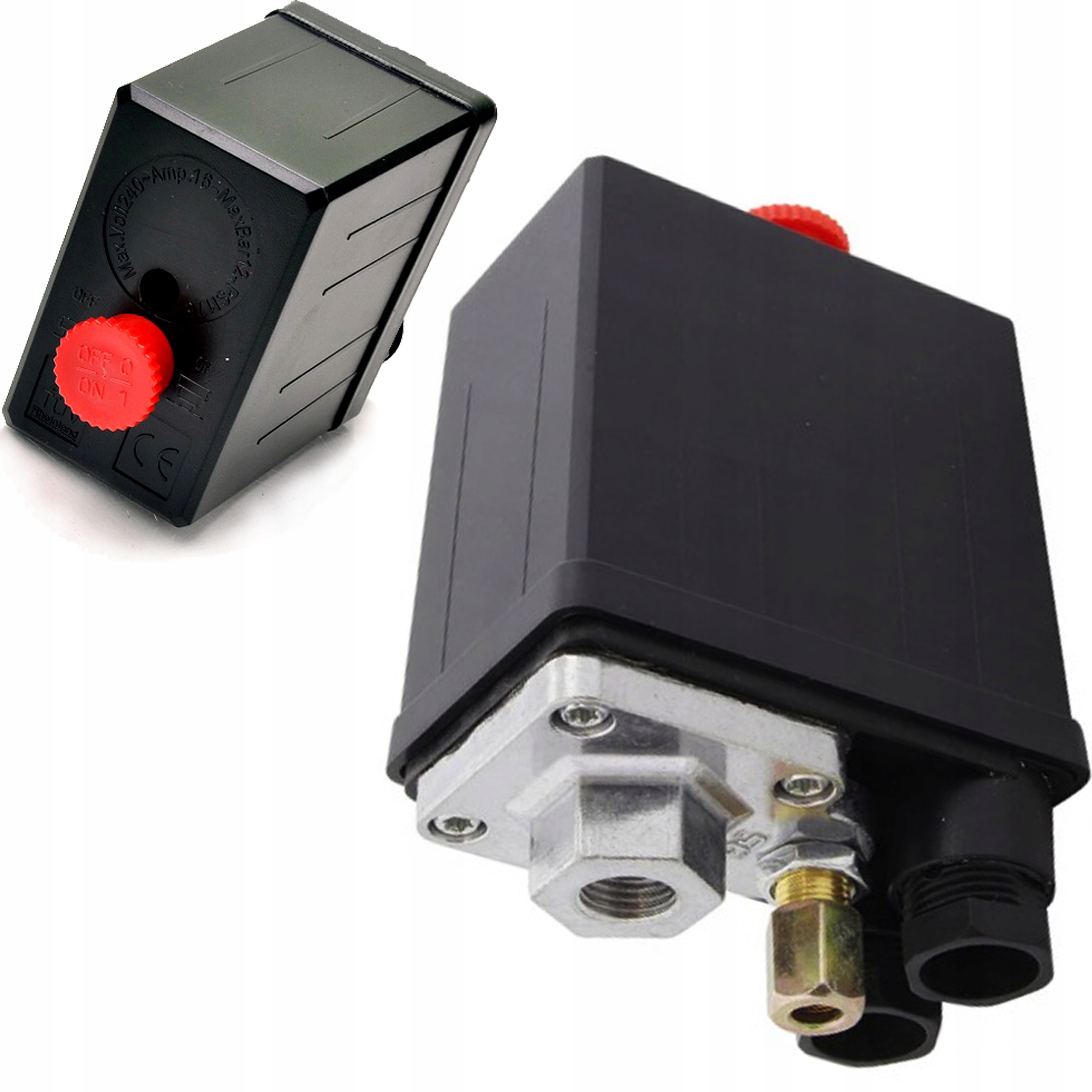
The pressure limits at which the compressor is switched on / off are regulated by a single bolt. In order not to be mistaken with the choice of direction for increasing / decreasing, arrows are marked on the metal base
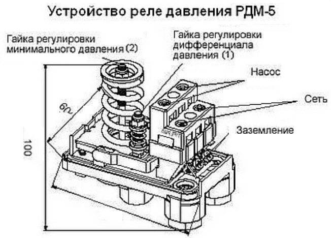
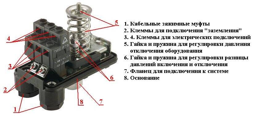
Having determined the level to be set, it is necessary to remove the relay housing. Under it there are two regulating elements - small and large nuts (in Figure 1.3).
Nearby there are arrow indicators of the direction in which the twisting will be carried out - thereby compressing and unclenching the spring mechanism (2.4).
The large screw clamp and spring are designed to control compression settings. When twisting clockwise, the spiral is compressed - the compressor cut-off pressure increases. Reverse adjustment - weakens, respectively, the pressure level for shutdown decreases.
It is worth remembering: by increasing the shutdown compression force, we change the factory settings, which are set in accordance with the regulatory requirements for the operation of the equipment. Before making adjustments, look at the technical documentation of the device so as not to exceed the limits declared by the manufacturer
When playing the settings, the receiver must be at least 2/3 full.
Having understood the purpose of the elements, we proceed:
- To ensure the proper level of security, turn off the power supply.
- Changing the level of compression of the springs is carried out by turning the nut several turns in the required direction. On the board near the large-diameter adjusting screw, according to standards, there is a symbol in Latin P (Pressure), a smaller one - ΔР.
- The control of the adjustment process is carried out visually on the pressure gauge.
Some manufacturers, for convenience, take out the adjusting fittings to change the nominal value on the surface of the device case.
DIY pressure switch
With known skills, as well as the presence of a working thermostat from a decommissioned refrigerator, the pressure switch can be made independently. True, he will not have special practical capabilities, since the ability to hold upper pressure is limited by the strength of the rubber bellows.
Thermal relays of the KTS 011 type are most convenient for conversion into a compressor pressure switch, since they have a strictly reverse sequence of their operation: when the temperature in the refrigeration chamber increases, the relay turns on, and when it drops, it turns off.
The essence and sequence of the work is as follows. After opening the cover, the location of the desired group of contacts is established, for which it is enough to ring the circuit. First, the connection of the thermostat to the compressor is being finalized. To do this, the outlet pipe, together with a control pressure gauge, is connected to the unloading valve, and the contact groups are connected to the terminals of the electric motor circuit. An adjustment screw will be found under the thermostat cover. When the compressor is turned on (the receiver must be filled with no more than 10 ... 15% of its nominal volume), the screw is sequentially rotated, controlling the result according to the pressure gauge. To set the lower position (determining the minimum air pressure), you will have to gradually move the stem of the face button. To do this, the cover is put in place, and the adjustment is actually done blindly, since there is nowhere to connect the second pressure gauge.
For safety reasons, the pressure adjustment range using such a thermal switch cannot be more than 1 ... 6 atm, however, using devices with a stronger bellows, you can increase the upper range to 8 ... 10 atm, which in most cases is quite enough.
After checking the operability of the relay, the capillary tube is cut off and the refrigerant located there is released. The end of the tube is soldered into the unloading valve.
Next, work is carried out to connect a home-made pressure switch to the compressor control circuit: with the help of a nut, the relay is connected to the control board, a thread is made on the stem, and a lock nut is screwed on, turning which, you can adjust the limits of air pressure change.
Considering that the contact group of any thermal relay from the refrigerator is designed for sufficiently large currents, in this way it is possible to switch circuits of considerable power, including the secondary control circuits of the compressor engine.


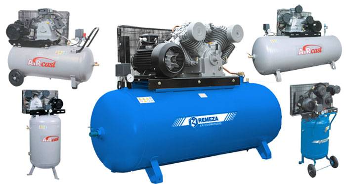
One of the main indicators of air compressors is the working pressure. In other words, this is the level of air compression created in the receiver, which must be maintained within a certain range. It is inconvenient to do this manually, referring to the pressure gauge readings, therefore, the compressor automation unit is responsible for maintaining the required compression level in the receiver.
Types of pressure switches
There are only two variations of the automatic compressor unit. The definition is based on their principle of operation. In the first version, the mechanism turns off the electric motor at the moment when the established limits of the air mass pressure level in the pneumatic network are exceeded. These devices are called normally open.
Schematic arrangement of the membrane pressure switch: 1 - pressure transducer; 2 and 3 - contacts; 4 - piston; 5 - spring; 6 - membrane; 7 - threaded connection
Another model with the opposite principle - turns on the engine if it detects a decrease in pressure below the allowable mark. Devices of this type are called normally closed.
Conclusion
The compressor is easier to maintain immediately after commissioning.
It is easy to avoid errors in operation if you carefully study the instructions for the device:
- Before starting the unit, check the compressor oil and top up if necessary.
- Every 16 hours of operation, drain the moisture from the receiver.
- Every 2 years it is worth inspecting the check valve on the compressor.
- The presence of grounding of non-current-carrying parts is mandatory.
Compliance with such requirements and careful attention to the compressor will reduce the cost of operating the device.
Common Compressor Faults
PISTON COMPRESSORS
SCREW COMPRESSORS


