- Tank preparation and adjustment
- An example of a complete set of a pumping station with a pump "Kid".
- How to connect the pump to the well and water supply
- Pressure switch RDM-5 - adjustment instructions
- Types of pressure switches
- How to properly adjust the relay and calculate the pressure
- Practical examples of relay settings
- Connecting a new device
- Pump stopped turning off
- Situations that do not require adjustment
- How to adjust the pressure
- Carrying out work on connecting and setting up a pressure switch for a hydraulic accumulator
- Standard scheme for connecting a pressure switch to a hydraulic accumulator
- Correct setting of the accumulator pressure switch
- Optimal pressure inside the hydraulic tank
- The need to adjust the water pressure switch for the pump
- Optimal pressure inside the hydraulic tank
- Hydraulic accumulator connection diagram for water supply systems
- Option 1
- Option 2
- Option 3
- Purpose and device
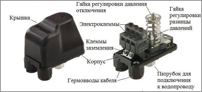
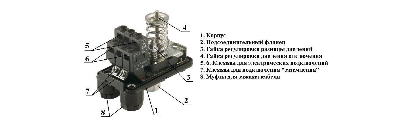
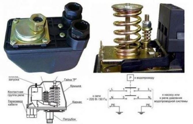
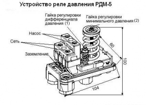
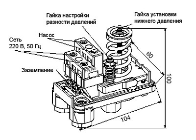
- Pressure switch device
- Species and varieties
- Connecting and setting the water pressure switch
Tank preparation and adjustment
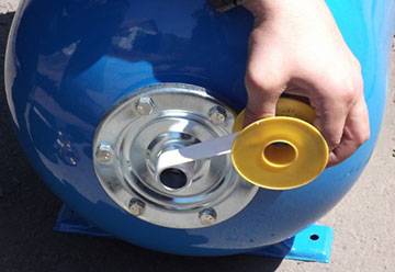
Before the accumulators go on sale, air is pumped into them at a certain pressure at the factory. Air is pumped through the spool installed on this container.
Under what pressure is the air in the hydraulic tank, you can find out from the label glued to it. In the following figure, the red arrow indicates the line in which the air pressure in the accumulator is indicated.
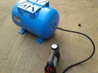
Also, these measurements of the compression force in the tank can be made using an automobile pressure gauge. The measuring device is connected to the spool of the tank.
To start adjusting the compression force in the hydraulic tank, you need to prepare it:
- Disconnect the equipment from the mains.
- Open any faucet installed in the system and wait until the liquid stops flowing from it. Of course, it will be better if the crane is located near the drive or on the same floor with it.
- Next, measure the compression force in the container using a pressure gauge and note this value. For small volume drives, the indicator should be about 1.5 bar.
In order to properly adjust the accumulator, the rule should be taken into account: the pressure that triggers the relay to turn on the unit must exceed the compression force in the accumulator by 10%. For example, the pump relay turns on the motor at 1.6 bar. This means that it is necessary to create an appropriate air compression force in the drive, namely 1.4-1.5 bar. By the way, the coincidence with the factory settings is not accidental here.
If the sensor is configured to start the engine of the station with a compression force greater than 1.6 bar, then, accordingly, the settings of the drive change. You can increase the pressure in the latter, that is, pump up air, if you use a pump for inflating car tires.
Advice! Correction of the air compression force in the accumulator is recommended to be carried out at least once a year, since during the winter it can decrease by several tenths of a bar.
An example of a complete set of a pumping station with a pump "Kid".
For an automatic pumping station you will need (minimum equipment):
— pump Malysh 750 r.
— hose 3/4″ reinforced, for pressure up to 6-8 atm.
— coarse filter 50r.
- hydraulic accumulator, capacity min. 20 l - about 1000 rubles.
- check valve 3/4 inch (placed in front of the accumulator) 100r.
- pressure gauge at 6 atm. 160 r.
- pressure switch model RDM 5 price approx. 500r.
- a fitting with 5 nipples (five) for connecting the entire household to each other.
- clamps for fixing hoses, sealing gaskets, flax for sealing threads.
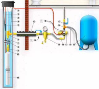
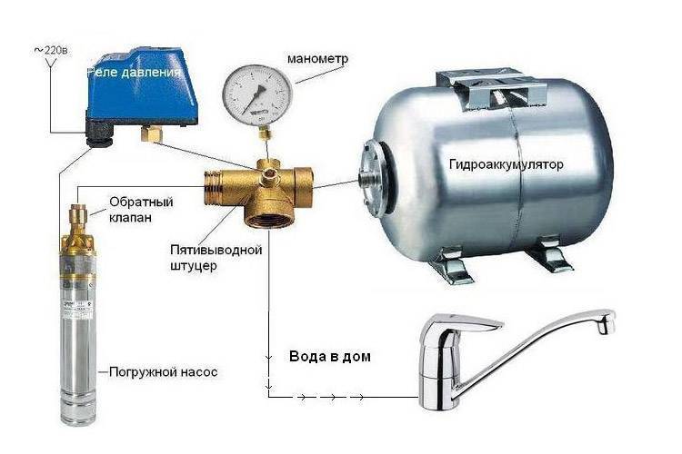
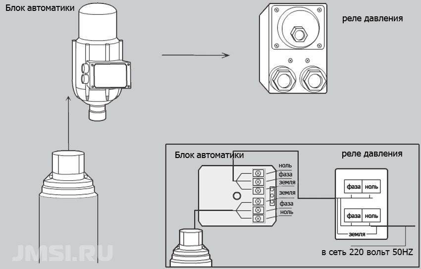
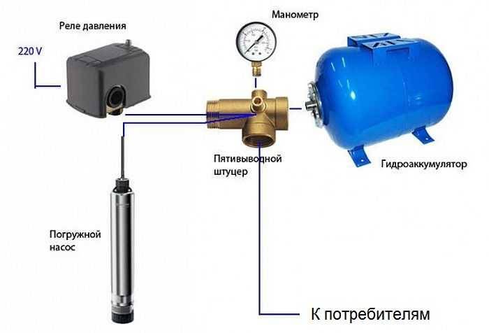
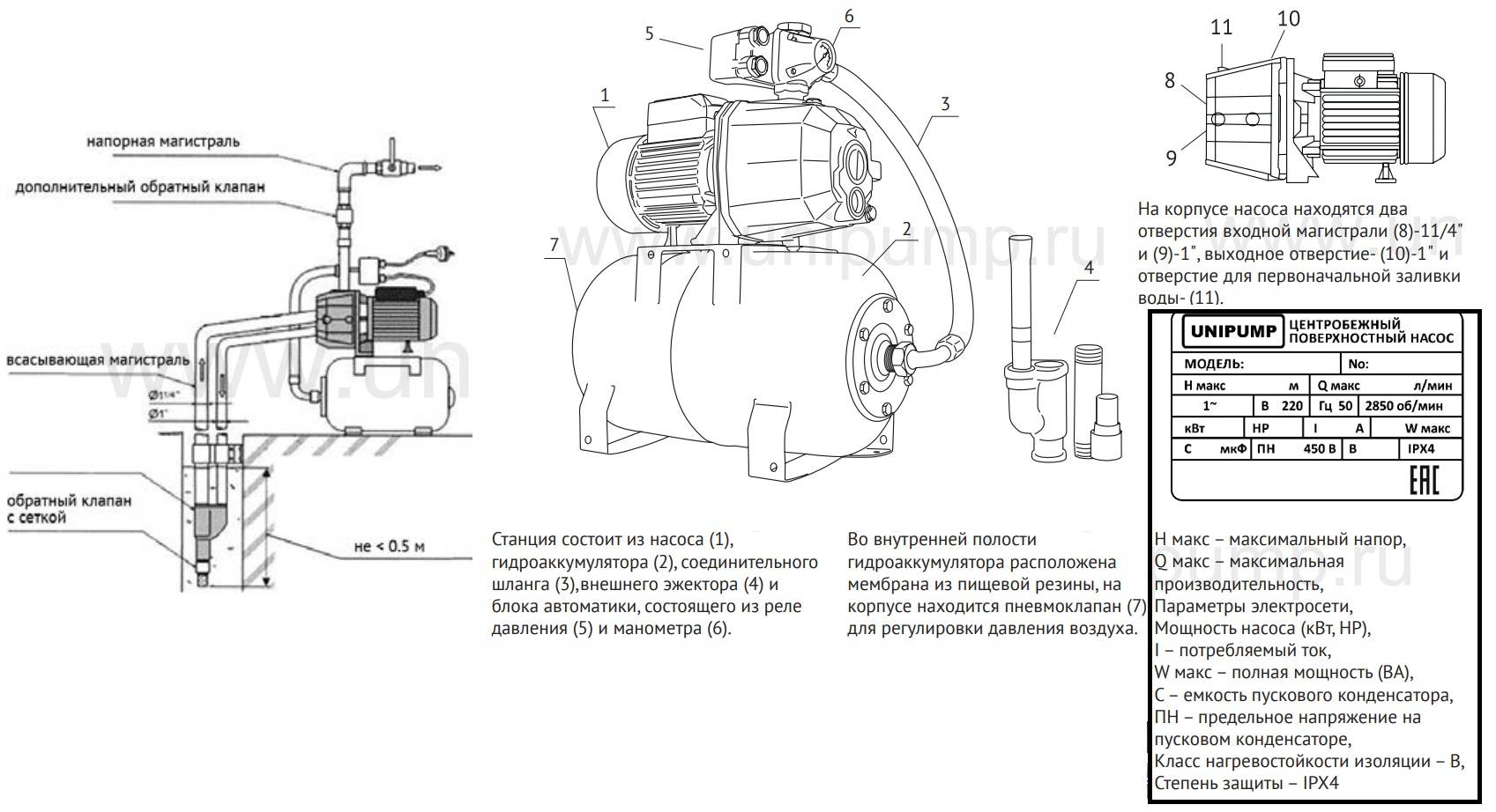
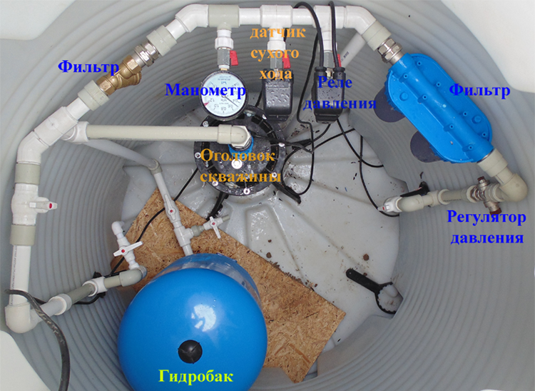
The water supply system is installed as follows. A hydraulic tank with an automation system is installed in a barn or in a house and is connected to a pump in a well with a hose and electrical wiring. From the hydraulic tank, water is supplied to consumers through a pipe. And now in more detail. We assemble the automation unit: we connect two electrical wires with plugs to the pressure switch, we screw a filter, a pressure gauge, a pressure switch onto the fiver and screw the entire structure into the accumulator. We connect a check valve to the filter with the direction of flow towards the hydraulic tank.
We connect the "Kid" pump with a flexible hose to a check valve. From the fiver on the accumulator we lead a pipe or hose to the consumer. Everything with hydraulics, now electrics. We install two sockets for the pump control system - one in the well and connect the pump plug to it, the second in the barn or in the house where the hydraulic accumulator with automatic equipment is located and connect the output voltage plug of the pressure switch to it.We install another outlet next to the accumulator, connect 220 V to it, lower the pump into the well and turn on the second plug of the pressure switch in the network. ALL. The water supply of the cottage is ready! The pump works and supplies water to the tank with the automation system. As soon as the pressure in the tank reaches the set one, the relay will work and turn off the pump. The maximum and minimum pressure in the system is regulated by a pressure switch.
How to connect the pump to the well and water supply
Before installing a submersible pump, a thorough cleaning of the well shaft is required. For this purpose, using a temporary pump, liquid is pumped out of the column until all sand and impurities are removed. To protect the pressure device from water hammer, a non-return valve must be installed on it.
The pump is connected to the well in the following sequence:
- Install the pipeline. When connecting the pump to a rigid pipe between it and the main line that transmits water to the consumer, it is better to insert a small piece of flexible hose to dampen the vibration of the electric motor.
- A cable, an electric wire, a hose are connected to the apparatus.
- The device is smoothly lowered into the well.
- When the pump reaches the bottom, it is raised by half a meter.
- The cable is rigidly fixed, the cable is connected to the mains, the hose is connected to the rest of the system and laid in the mounting channels.
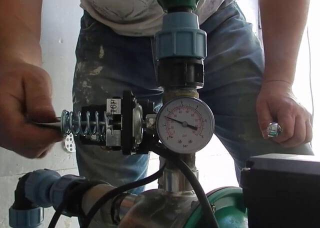
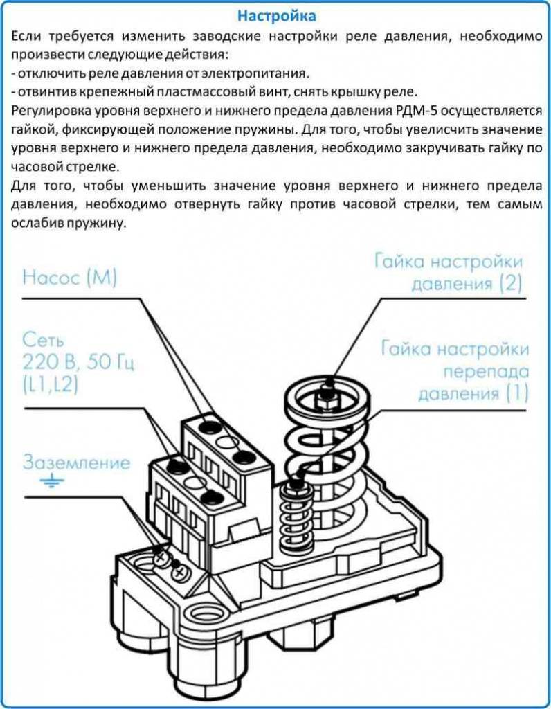
Pressure switch RDM-5 - adjustment instructions
In the case of a normal pressure indicator, the internal contacts of the device remain in their original position, without interfering with the free flow of water. But, as soon as this indicator starts to go off scale, the contact plates, under the pressure of the flow, open and the water supply pump connected to the relay turns off.

The basic setting of the activation sensor is carried out in the factory, and the device is delivered to the market already ready for installation. However, the adjustment instructions pressure switch RDM provides independent setting indicators, depending on the needs of the consumer.


First of all, the water supply must be equipped with a pressure gauge - in accordance with its indications, the adjustment will be carried out. Work on adjusting the device is carried out as follows:
- We connect the RDM to the system, in strict accordance with the operating instructions.
- The accumulator is not connected to the system, and the outlet leading to it is muffled.
- The pump is connected to the network, and the operation of the device is checked at the factory settings. At the same time, you can check the tightness of the pipeline to the installation site of the relay. The readings of the network pressure gauge should be stabilized at 3 atmospheres.
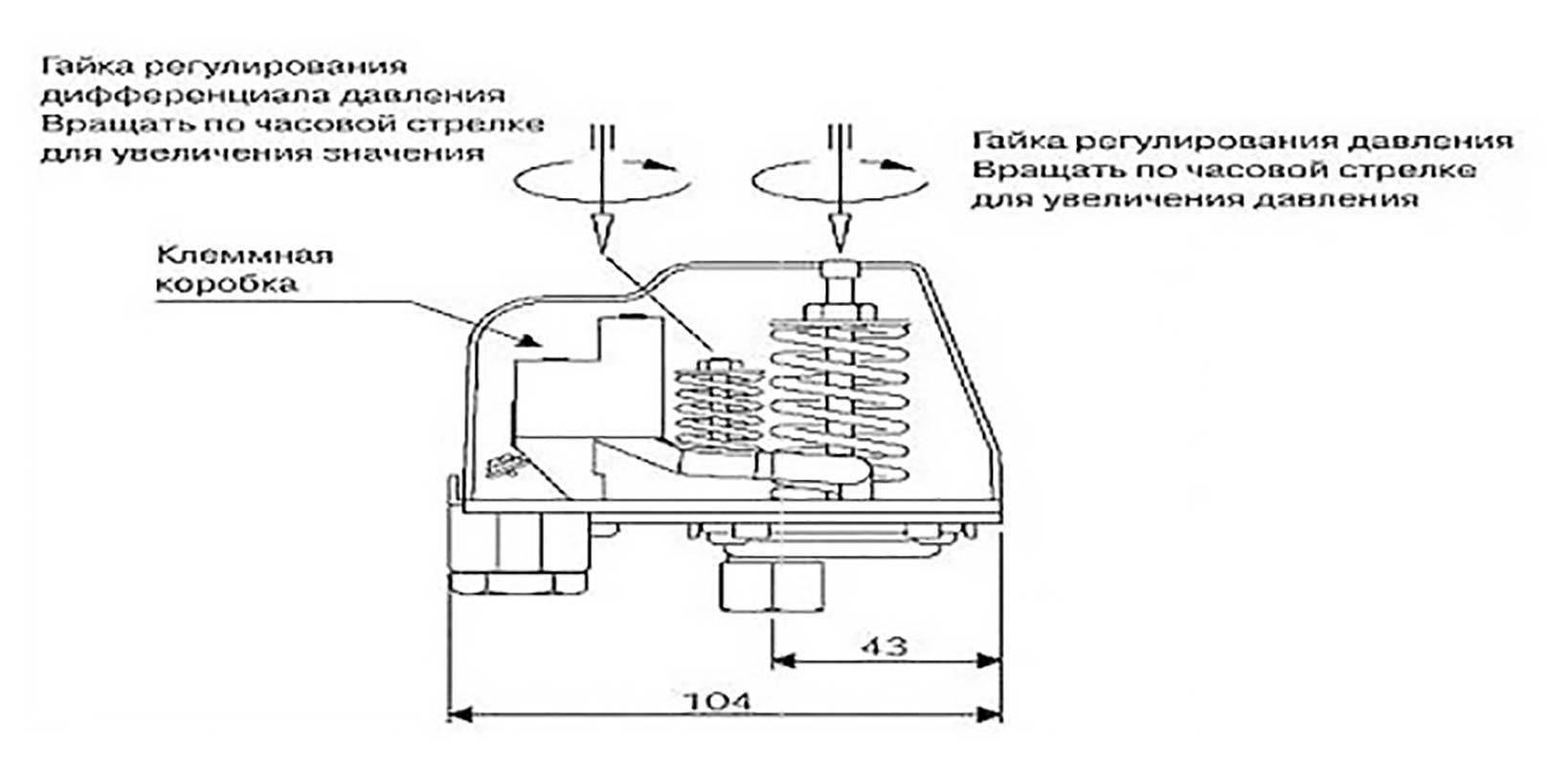
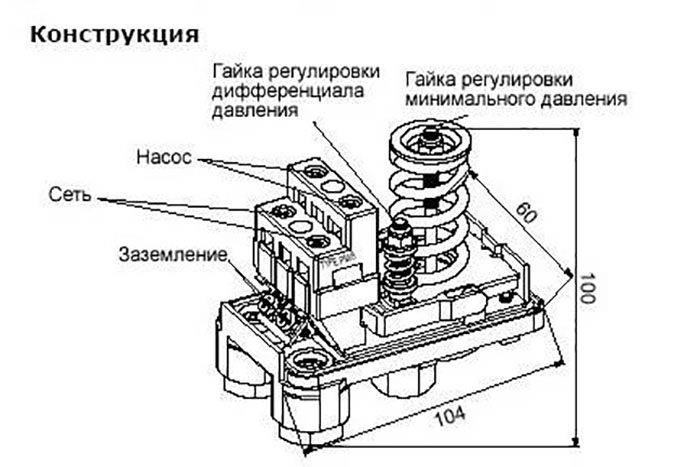
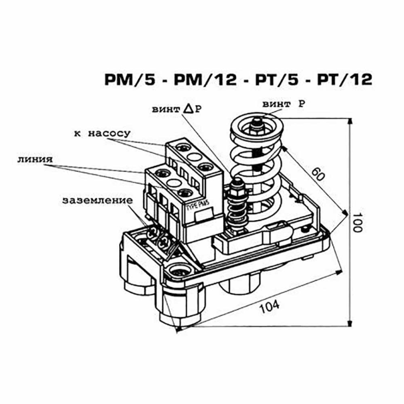
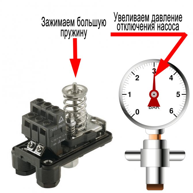
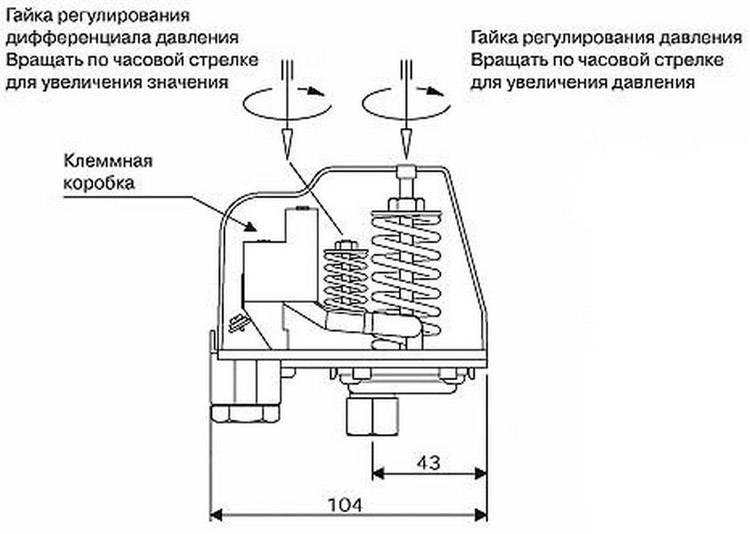
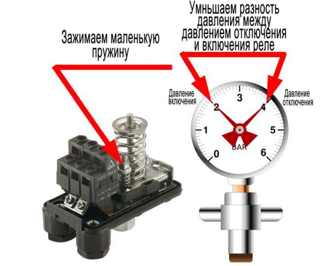
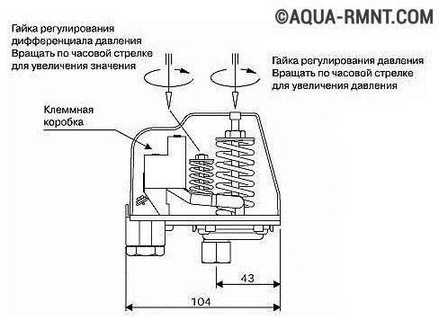
- Next, open the RDM cover, under which there are two nuts with springs - one larger, the other smaller. Turning the large nut clockwise will compress the spring. Thus, the upper limit of the sensor will be increased, and when rotating in the opposite direction, this limit will be lowered.
- By rotating the spring-loaded large nut, the required upper limit is set, say 2.9 atm. We leave the lower indicator in the factory version - 1 atm.
- Then we connect a hydraulic tank to the house system and, using a separate pressure gauge on it, we check the pressure inside it. The average for hydroaccumulators is about 1.5 atmospheres.
- We connect the hydraulic tank to the RDM device, start the pump and observe at what indicator of the internal network pressure the sensor will turn off the operation of the pumping equipment. According to the settings (1 atm. - the lower, and 2.9 - the upper limit), the operating pressure range is 1.9 atmospheres, which is 0.4 atm. more working pressure in the hydraulic tank.
According to the operating instructions, the operating range of the RDM-5 sensor should be 0.3 atm higher than the pressure in the hydraulic tank. In this case, the pump on / off cycles are optimized, which allows you to save motor resources and protect against breakdowns, as well as save additional electricity.
Helpful6Useless3
Types of pressure switches
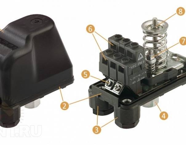
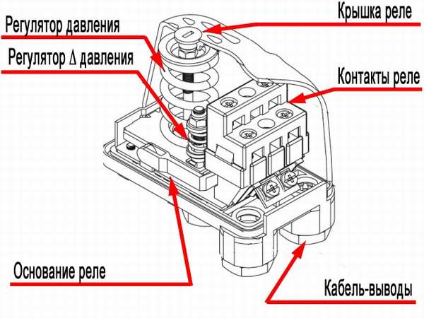
There are miniature and fairly large devices. Their difference lies also in equipping with additional functions. The classic relay for a hydraulic accumulator includes two working units:
The first one is intended for the interaction of the device with the liquid supplied to it. It consists of a rod and two springs. Due to the latter, the optimal pressure parameters are adjusted. The main task of the latter is to connect conductors to electricity. Represents metal terminals with clamping bolts. Depending on the position of the hydraulic part, the terminals open and close.
On the market or in specialized stores, you can purchase the following types of pressure switches:
- with dry running sensor;
- mechanical;
- equipped with a built-in pressure gauge;
- electronic.
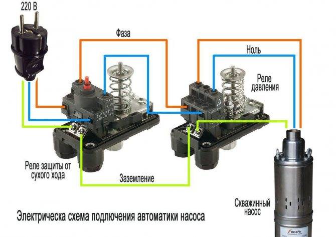
Electronic relays are equipped with additional modules that open and close contacts. They also have built-in electronic pressure gauges with a digital display.The dry running sensor prevents the pumping station from running “idle”, if, for example, the water level has dropped, the intake hole is clogged or the supply pipe has been damaged.
How to properly adjust the relay and calculate the pressure
All devices leave the production line with certain settings, but after purchase, additional verification must be performed. When buying, you need to find out from the seller what values the manufacturer recommends using when adjusting the depth pressure. In other words, the pressure at which the contacts close and open.
If the station fails due to improper adjustment of the pressure switch of the jumbo pumping station, then it will not be possible to use the manufacturer's warranty.
When calculating the cut-in pressure values, the following parameters are taken into account:
- Required pressure at the highest draw-off point.
- Difference in height between the top draw point and the pump.
- Loss of water pressure in the pipeline.
The value of the switching pressure is equal to the sum of these indicators.
The calculation of the turn-off pressure to solve the question of how to set up the pressure switch is performed as follows: the turn-on pressure is calculated, one bar is added to the value obtained, then one and a half bar is subtracted from the amount. The result should not exceed the value of the maximum allowable pressure that occurs at the outlet of the pipe from the pump.
Practical examples of relay settings
Let's analyze the cases when the appeal to the adjustment of the pressure switch is really necessary. This usually happens when buying a new appliance or when frequent pump shutdowns occur.
Also, setting will be required if you got a used device with downgraded parameters.
Connecting a new device
At this stage, you should check how correct the factory settings are and, if necessary, make some changes to the operation of the pump.
To track the progress of work, it is recommended to write down all the data received on a piece of paper. In the future, you can return the initial settings or change the settings again.
Pump stopped turning off
In this case, we forcibly turn off the pumping equipment and act in the following order:
- We turn on, and wait until the pressure reaches the maximum mark - suppose 3.7 atm.
- We turn off the equipment and lower the pressure by draining the water - for example, up to 3.1 atm.
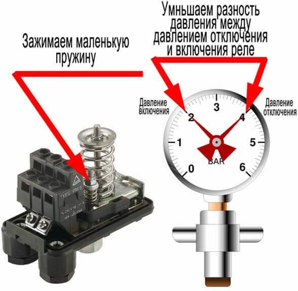
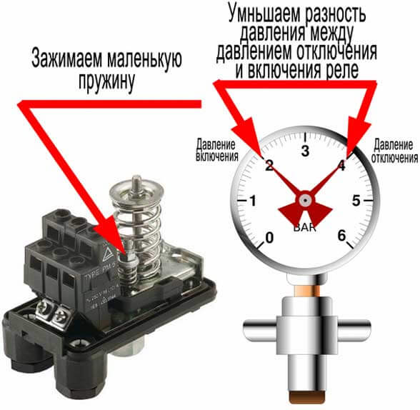
- Slightly tighten the nut on the small spring, increasing the value of the differential.
- We check how the cut-off pressure has changed and test the system.
- We adjust the best option by tightening and loosening the nuts on both springs.
If the cause was an incorrect initial setting, it can be solved without buying a new relay. It is recommended to regularly, once every 1-2 months, check the operation of the pressure switch and, if necessary, adjust the on / off limits.
Situations that do not require adjustment
There can be many reasons when the pump does not turn off or does not turn on - from a blockage in communications to engine failure. Therefore, before starting to disassemble the relay, you should make sure that the rest of the equipment of the pumping station is working properly.
If everything is in order with the rest of the devices, the problem is in the automation. We turn to the inspection of the pressure switch. We disconnect it from the fitting and wires, remove the cover and check two critical points: a thin pipe for connecting to the system and a block of contacts.
If the cleaning measures did not help, and the adjustment of the position of the springs was also in vain, most likely the relay is not subject to further operation and should be replaced with a new one.
Suppose you got an old but working device in your hands. Its adjustment takes place in the same order as the setting of a new relay. Before starting work, make sure that the device is intact, disassemble it and check that all contacts and springs are in place.
How to adjust the pressure
The correct operation of the pumping station is determined by three main parameters:
- Start pressure;
- Cut-off pressure;
- Air pressure in the hydraulic tank.
The first two parameters determine the operating mode of the pressure switch. Adjustment is carried out empirically, while in order to improve the accuracy of the measurement, the check can be performed several times.
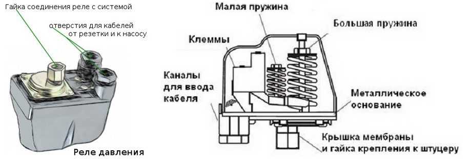
As part of the electrical relay: two vertical springs. They are located on the axles and tightened with nuts. One of the springs (larger diameter) is used to set the start pressure value, the smaller diameter spring is used to regulate the required difference between the starting pressure and the shutdown pressure of the pump. The springs rest against the membrane, which closes and opens the contacts of the control circuit.
The adjustment process is carried out in the following sequence:
- Measuring the air pressure in the receiver using an external pressure gauge (for example, a car), if necessary, pumping it up with a hand pump or compressor to the calculated value. It is carried out with the pump turned off after complete pressure relief.
- Pump activation pressure measurement.With the pump turned on but not running, open the valve to relieve pressure and take the reading of the system pressure gauge at the moment the relay is triggered (when the pumping station is started).
- Start pressure adjustment. If the obtained pressure value does not match the required one, turn the nut of the large spring in the direction of increasing or decreasing. After completion of the control measurement, if necessary, repeat the operation (possibly several times).
- Measurement of pump cut-off pressure. Close all drain cocks and wait for the pump to turn off.
- Adjustment of the difference in pressure levels for starting and shutting down the pump. If the calculated value of the shutdown threshold of the pumping station does not match, turn the spring nut of a smaller diameter in the appropriate direction. The spring is very sensitive: turn to a maximum of 1/4 - 1/2 turn. After conducting a control measurement, repeat the steps if necessary.
- Repeat the cycle described in paragraphs 1 - 5. If necessary, repeat the procedure several times until the desired parameters are reached.
The required start-up and shutdown parameters are indicated in the relay passport. The working air pressure in the receiver is indicated in the battery passport. It should be 10-12% less than the starting pressure.
It should be noted that the described technology for monitoring and setting battery parameters is the same for all types of this product, regardless of the configuration (vertical or horizontal version), volume and design features. This is also true for heating and hot water systems.
It is not necessary to be a specialist in order to carry out simple operations to check and adjust the pressure in the accumulator, having a minimum of simple tools. Simple actions that do not require any skills will take a minimum of time, while they will pay off with reliable uninterrupted operation of the water supply system for a long time.
Carrying out work on connecting and setting up a pressure switch for a hydraulic accumulator
Although many people find the process of mounting and adjusting the device difficult to understand, in fact it is not. Each owner of a country house with a well or a well can independently connect and configure a device to provide the building with water.
One of the schemes for connecting the accumulator to the system
Standard scheme for connecting a pressure switch to a hydraulic accumulator
The finished product interacts with both the plumbing and electrical systems of the building. When closing and opening contacts, liquid is supplied or blocked. The pressure device is installed permanently, since there is no need to move it from place to place.
The purpose of the contact groups of the device is indicated
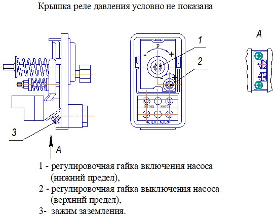
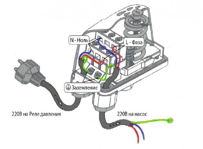
For connection, it is recommended to allocate a separate power line. Directly from the shield should be a cable with a copper core section of 2.5 square meters. mm. It is not recommended to connect wires without grounding, because the combination of water and electricity is fraught with hidden danger.
Visual diagram for independent connection of the relay
Cables should be passed through the holes located on the plastic case, and then connected to the terminal block. It contains terminals for phase and zero, ground. wires for the pump.

Note! Electrical work must be carried out in a disconnected state from the network. When installing, you must not neglect the observance of the general rules of technical safety
Correct setting of the accumulator pressure switch
To adjust the device, an accurate pressure gauge is required to determine the pressure without errors. Focusing on its readings, you can make a relatively quick adjustment. By turning the nuts located on the springs, you can reduce or increase the pressure. During setup, you must follow a certain sequence of actions.
Work is underway to set up the device
So, the adjustment of the pressure switch for the accumulator is carried out as follows.
- The system turns on, after which, using a pressure gauge, the indicators are monitored at which the device is turned on and off;
- First, the lower level spring, which is large, is adjusted. For adjustment, a regular wrench is used.
- The set threshold is being tested. If necessary, the previous paragraph is repeated.
- Next, the nut is turned for the spring, which allows you to set the upper pressure level. It has a smaller size.
- The operation of the system is fully tested. If for some reason the results are not satisfactory, then a reconfiguration is performed.
The adjusting nuts of the device are shown
Note! Before you set up the accumulator pressure switch, you need to remember a simple truth. The minimum allowable difference between the maximum and minimum value should not be less than 1 atmosphere
Optimal pressure inside the hydraulic tank
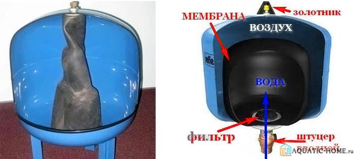
Any accumulator inside has a rubber membrane that divides the space into two chambers. One contains water and the other contains compressed air. Thanks to this structure, it is possible to create the necessary pressure when filling and emptying the rubber container.

The device of the hydraulic accumulator is clearly shown
To extend the life of the device, you need to know what pressure should be in the accumulator. It largely depends on the indicators set to turn on the pump. The pressure inside the tank should be about 10 percent less.
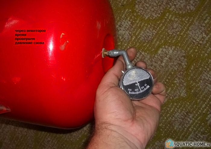
Tank pressure check
For example, if the switch-on is set to 2.5 bar and the switch-off is set to 3.5 bar, then the air pressure inside the tank should be set to 2.3 bar. Ready-made pumping stations usually do not require additional adjustment.
The need to adjust the water pressure switch for the pump
Setting up the relay independently or with the involvement of qualified specialists is required in any case when assembling the pumping station from separate parts. It is possible that setting the water pressure switch will be required even if the finished pumping station is purchased from a specialized store.
This is explained by the fact that each water supply system is characterized by individual characteristics and the needs of residents are also different. The degree of water pressure in a house with a shower, sink and bathtub is significantly different from a spacious country house with a jacuzzi and hydromassage. In this case, it is necessary to adjust the water pressure in the water supply system and configure the equipment individually for each case.
When deciding how to connect a water pressure switch, it should be remembered that in addition to the initial setup that is performed during the installation of pumping equipment, during operation it is necessary to monitor and adjust the operation of the equipment.
In addition, in the case of replacing or repairing a separate element of the pumping station, additional adjustment of the water pressure regulator relay is also required. It is worth saying that the process of adjusting equipment is similar to the procedure for setting it up.
Optimal pressure inside the hydraulic tank
Any accumulator inside has a rubber membrane that divides the space into two chambers. One contains water and the other contains compressed air. Thanks to this structure, it is possible to create the necessary pressure when filling and emptying the rubber container.
The device of the hydraulic accumulator is clearly shown
To extend the life of the device, you need to know what pressure should be in the accumulator. It largely depends on the indicators set to turn on the pump. The pressure inside the tank should be about 10 percent less.
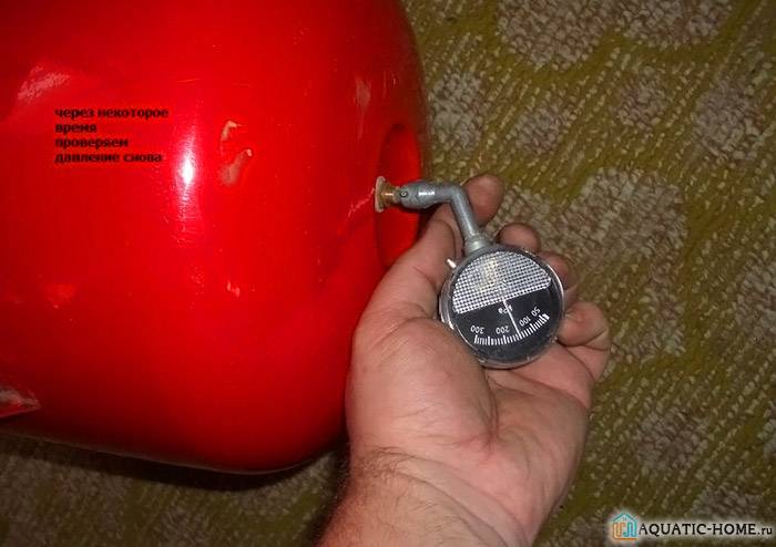
Tank pressure check
For example, if the switch-on is set to 2.5 bar and the switch-off is set to 3.5 bar, then the air pressure inside the tank should be set to 2.3 bar. Ready-made pumping stations usually do not require additional adjustment.
Hydraulic accumulator connection diagram for water supply systems
The method of connecting the GA will depend on the features and purpose of the pumping station. Let's consider three options.
Option 1
In this case, the GA is installed inside the house in any convenient place.
Usually it, a pressure switch and a pressure gauge are connected using a five-pin fitting - a piece of pipe with three outlets that cuts into the water supply.
To protect the GA from vibrations, it is attached to the fitting with a flexible adapter. To check the pressure in the air chamber, as well as to remove air accumulated in the water chamber, the HA must be emptied periodically. Water can be drained through any water tap, but for convenience, a drain valve can be inserted through a tee into the supply pipeline somewhere near the tank.
Option 2
The house is connected to a centralized water supply, and a pumping station is used to increase pressure. With this method of application, the GA stations are connected in front of the pump.
In this case, it is designed to compensate for the decrease in pressure in the external line at the time of starting the electric motor. With such a connection scheme, the volume of the HA is determined by the pump power and the magnitude of pressure surges in the external network.
Installation of a hydraulic accumulator - diagram
Option 3
A storage water heater is connected to the water supply. GA should be connected to the boiler. In this embodiment, it can be used to compensate for the increase in water volume in the heater due to thermal expansion.
Purpose and device
In order to maintain a constant pressure in the water supply system of a private house, two devices are needed - a hydraulic accumulator and a pressure switch. Both of these devices are connected to the pump through the pipeline - the pressure switch is located in the middle between the pump and the accumulator.Most often, it is located in the immediate vicinity of this tank, but some models can be installed on the pump housing (even submersible). Let's understand the purpose of these devices and how the system works.
One of the pump connection diagrams
A hydraulic accumulator is a container divided by an elastic pear or membrane into two halves. In one, air is under some pressure, in the second, water is pumped. The water pressure in the accumulator and the amount of water that can be pumped there is regulated by the amount of air pumped. The more air, the higher the pressure maintained in the system. But at the same time, less water can be pumped into the tank. Usually it is possible to pump no more than half of the volume into the container. That is, it will be possible to pump no more than 40-50 liters into a hydraulic accumulator with a volume of 100 liters.
For normal operation of household appliances, a range of 1.4 atm - 2.8 atm is required. To support such a framework, a pressure switch is required. It has two operation limits - upper and lower. When the lower limit is reached, the relay starts the pump, it pumps water into the accumulator, and the pressure in it (and in the system) increases. When the pressure in the system reaches the upper limit, the relay turns off the pump.
In a circuit with a hydroaccumulator, for some time water is consumed from the tank. When enough flows out so that the pressure drops to the lower threshold, the pump will turn on. That's how this system works.
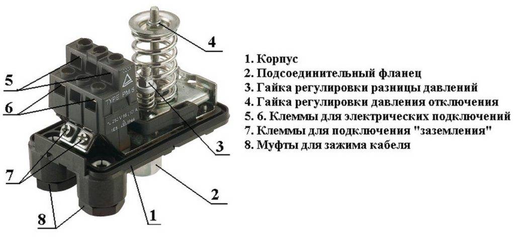
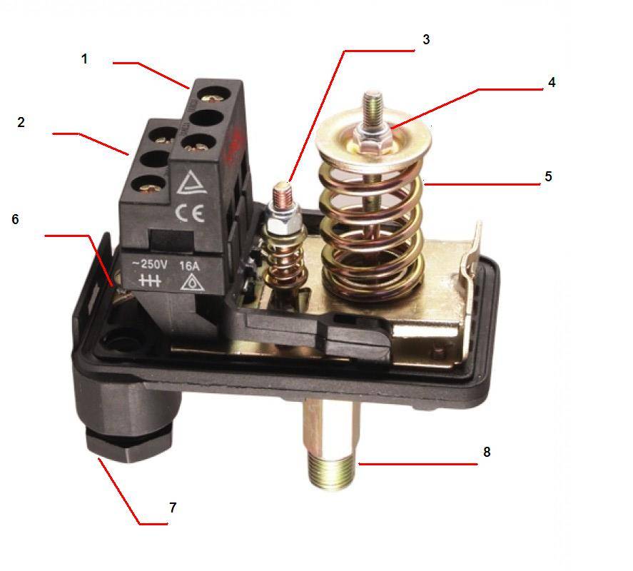

Pressure switch device
This device consists of two parts - electrical and hydraulic. The electrical part is a group of contacts that closes and opens on / off the pump. Hydraulic part - membrane, which puts pressure on metal base and springs (large and small) with which the pressure on / off the pump can be changed.
Water pressure switch device
The hydraulic outlet is located on the back of the relay. It can be an outlet with an external thread or with a nut like an American. The second option is more convenient during installation - in the first case, you either need to look for an adapter with a union nut of a suitable size or twist the device itself by screwing it onto the thread, and this is not always possible.
The electrical inputs are also located on the back of the case, and the terminal block itself, where the wires are connected, is hidden under the cover.
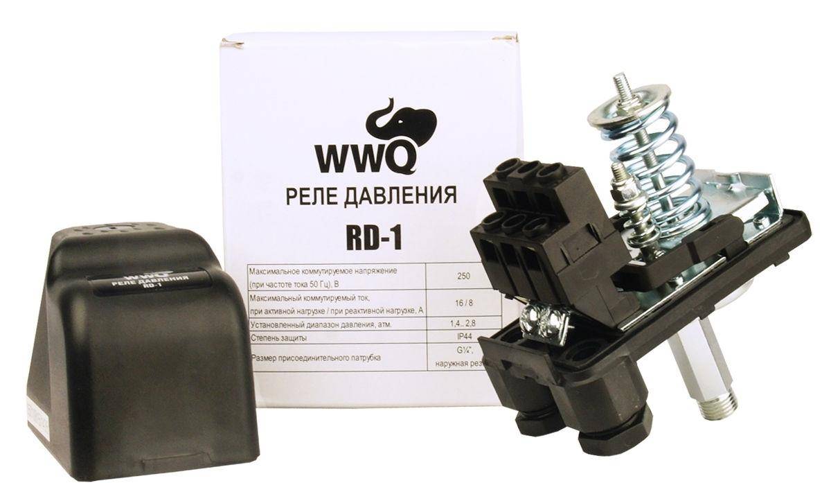
Species and varieties
There are two types of water pressure switches: mechanical and electronic. Mechanical ones are much cheaper and usually prefer them, while electronic ones are mostly brought to order.
| Name | Pressure adjustment limit | Factory settings | Manufacturer/country | Device protection class | Price |
|---|---|---|---|---|---|
| RDM-5 Gileks | 1- 4.6 atm | 1.4 - 2.8 atm | Gilex/Russia | IP44 | 13-15$ |
| Italtecnica RM/5G (m) 1/4″ | 1 - 5 atm | 1.4 - 2.8 atm | Italy | IP44 | 27-30$ |
| Italtecnica RT/12 (m) | 1 - 12 atm | 5 - 7 atm | Italy | IP44 | 27-30$ |
| Grundfos (Condor) MDR 5-5 | 1.5 - 5 atm | 2.8 - 4.1 atm | Germany | IP 54 | 55-75$ |
| Italtecnica PM53W 1″ | 1.5 - 5 atm | Italy | 7-11 $ | ||
| Genebre 3781 1/4″ | 1 - 4 atm | 0.4 - 2.8 atm | Spain | 7-13$ |
The difference in prices in different stores is more than significant. Although, as usual, when buying cheap copies, there is a risk of running into a fake.
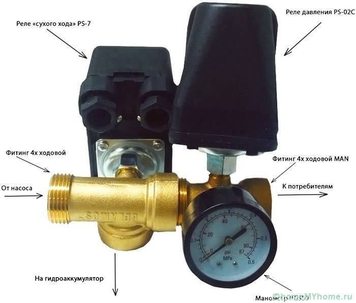
Connecting and setting the water pressure switch
First of all, the accumulator pressure switch must be connected to the pipeline by screwing it onto a threaded pipe (usually ¼ inch).
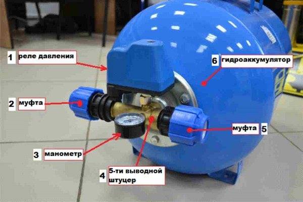
The most convenient way to connect a relay, a pressure gauge and a hydraulic accumulator is to use the so-called five-pin fitting, which is a tube with three taps expanding on one side.
If such a part is not available, for each of the listed elements you will have to embed a tee or weld a bend.
When screwing on the relay, you have to rotate it entirely (the nut is rigidly fixed), so you should take care in advance that it does not rest against anything.
To prevent water from seeping through the threaded connection, it must be sealed. Usually, winding from tow, sanitary flax or fum tape is used for this. In the absence of practice at this stage, difficulties may arise. The sealant can slip and get stuck, but the most difficult thing is to find the optimal amount.
With a lack of flax or tow, nothing terrible will happen - when the pump is turned on, the connection will leak and it will just need to be redone by adding a little sealant.
Pressure switch with hydraulic accumulator assembly
But with an excess of this material, the relay nut may burst. If you feel unsure about threaded connections, use the Tanget Unilok sealing thread. It is more expensive than conventional winding, but it is easier to use and, even with an excessive amount, does not cause destruction of the screwed-on part. Each package contains detailed instructions for the use of this sealant.
The winding of the Tanget Unilok thread should not be started from the end of the pipe, but from the point on the thread to which it is supposed to screw the nut, that is, you need to move towards the end.
The material should be laid in a clockwise direction (when viewed from the end of the nozzle), with the first loop wound so that the thread presses itself.


