- Features of the selection of a circulation pump
- Expansion tank volume
- Let's talk about the amount of pumped fluid in more detail.
- Calculation of the pump for the heating system
- Pump marking
- Heat requirement of the room
- Self-calculation
- The main types of pumps for heating
- Wet equipment
- "Dry" variety of devices
- The use of circulation pumps in home heating
- closed system
- Open heating system
- Underfloor heating system
- As in practice, the hydraulic resistance of the heating system is considered.
- Approximate formulas for calculating hydraulic resistance.
- Programs for calculating hydraulic resistance in heating systems.
- Head of pumping equipment of circulation type
- Conclusions and useful video on the topic
Features of the selection of a circulation pump
The pump is selected according to two criteria:
- The amount of liquid pumped, expressed in cubic meters per hour (m³/h).
- Head expressed in meters (m).
With pressure, everything is more or less clear - this is the height to which the liquid must be raised and is measured from the lowest to the highest point or to the next pump, if the project provides for more than one.
Expansion tank volume
Everyone knows that a liquid tends to increase in volume when heated.So that the heating system does not look like a bomb and does not flow at all seams, there is an expansion tank into which the displaced water from the system is collected.
What volume should be purchased or made a tank?
It's simple, knowing the physical characteristics of water.
The calculated volume of coolant in the system is multiplied by 0.08. For example, for a coolant of 100 liters, the expansion tank will have a volume of 8 liters.
Let's talk about the amount of pumped fluid in more detail.
The water consumption in the heating system is calculated according to the formula:
G = Q / (c * (t2 - t1)), where:
- G - water consumption in the heating system, kg / s;
- Q is the amount of heat that compensates for heat loss, W;
- c - specific heat capacity of water, this value is known and equal to 4200 J / kg * ᵒС (note that any other heat carriers have worse performance compared to water);
- t2 is the temperature of the coolant entering the system, ᵒС;
- t1 is the temperature of the coolant at the outlet of the system, ᵒС;
Recommendation! For a comfortable stay, the temperature delta of the heat carrier at the inlet should be 7-15 degrees. The floor temperature in the "warm floor" system should not be more than 29ᵒ C. Therefore, you will have to figure out for yourself what type of heating will be installed in the house: will there be batteries, a “warm floor” or a combination of several types.
The result of this formula will give the coolant flow rate per second of time to replenish heat losses, then this indicator is converted into hours.
Advice! Most likely, the temperature during operation will vary depending on the circumstances and the season, so it is better to immediately add 30% of the reserve to this indicator.
Consider the indicator of the estimated amount of heat required to compensate for heat losses.
Perhaps this is the most complex and important criterion that requires engineering knowledge, which must be approached responsibly.
If this is a private house, then the indicator can vary from 10-15 W / m² (such indicators are typical for "passive houses") to 200 W / m² or more (if it is a thin wall with no or insufficient insulation).
In practice, construction and trade organizations take as a basis the heat loss indicator - 100 W / m².
Recommendation: Calculate this indicator for a particular house in which a heating system will be installed or reconstructed. To do this, heat loss calculators are used, while losses for walls, roofs, windows, and floors are separately calculated. These data will make it possible to find out how much heat is physically given off by the house to the environment in a particular region with its own climatic regimes.
We multiply the calculated loss figure by the area of \u200b\u200bthe house and then substitute it into the water consumption formula.
Now you should deal with such a question as water consumption in the heating system of an apartment building.
Calculation of the pump for the heating system
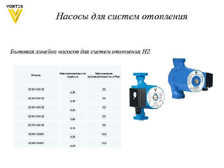
Selection of a circulation pump for heating
The type of pump must be necessarily circulation, for heating and withstand high temperatures (up to 110 ° C).
The main parameters for selecting a circulation pump:
2. Maximum head, m
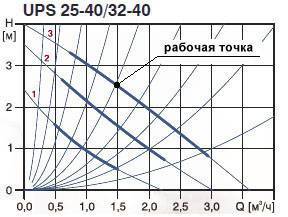
For a more accurate calculation, you need to see a graph of the pressure-flow characteristic
Pump characteristic is the pressure-flow characteristic of the pump. Shows how the flow rate changes when exposed to a certain pressure loss resistance in the heating system (of a whole contour ring). The faster the coolant moves in the pipe, the greater the flow.The greater the flow, the greater the resistance (pressure loss).


Therefore, the passport indicates the maximum possible flow rate with the minimum possible resistance of the heating system (one contour ring). Any heating system resists the movement of the coolant. And the larger it is, the less will be the overall consumption of the heating system.
Intersection point shows the actual flow and head loss (in meters).
System characteristic - this is the pressure-flow characteristic of the heating system as a whole for one contour ring. The greater the flow, the greater the resistance to movement. Therefore, if it is set for the heating system to pump: 2 m 3 / hour, then the pump must be selected in such a way as to satisfy this flow rate. Roughly speaking, the pump must cope with the required flow. If the heating resistance is high, then the pump must have a large pressure.
In order to determine the maximum pump flow rate, you need to know the flow rate of your heating system.
In order to determine the maximum pump head, it is necessary to know what resistance the heating system will experience at a given flow rate.
heating system consumption.
The consumption strictly depends on the required heat transfer through the pipes. To find the cost, you need to know the following:
2. Temperature difference (T1 and T2) supply and return pipelines in the heating system.
3. The average temperature of the coolant in the heating system. (The lower the temperature, the less heat is lost in the heating system)
Suppose that a heated room consumes 9 kW of heat. And the heating system is designed to give 9 kW of heat.
This means that the coolant, passing through the entire heating system (three radiators), loses its temperature (See image). That is, the temperature at point T1 (in service) always over T2 (on the back).
The greater the coolant flow through the heating system, the lower the temperature difference between the supply and return pipes.
The higher the temperature difference at a constant flow rate, the more heat is lost in the heating system.
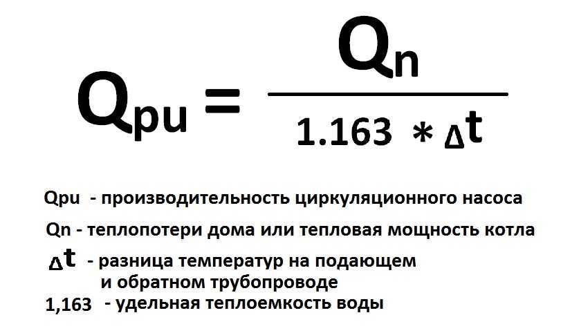
C - heat capacity of the water coolant, C \u003d 1163 W / (m 3 • ° C) or C \u003d 1.163 W / (liter • ° C)
Q - consumption, (m 3 / hour) or (liter / hour)
t1 – Supply temperature
t2 – The temperature of the cooled coolant
Since the loss of the room is small, I suggest counting in liters. For large losses, use m 3
It is necessary to determine what the temperature difference will be between the supply and the cooled coolant. You can choose absolutely any temperature, from 5 to 20 °C. The flow rate will depend on the choice of temperatures, and the flow rate will create some coolant velocities. And, as you know, the movement of the coolant creates resistance. The greater the flow, the greater the resistance.
For further calculation, I choose 10 °C. That is, on the supply 60 ° C on the return 50 ° C.
t1 – Temperature of the giving heat carrier: 60 °C
t2 – Temperature of the cooled coolant: 50 °С.
W=9kW=9000W
From the above formula I get:
Answer: We got the required minimum flow rate of 774 l/h
heating system resistance.
We will measure the resistance of the heating system in meters, because it is very convenient.
Suppose we have already calculated this resistance and it is equal to 1.4 meters at a flow rate of 774 l / h
It is very important to understand that the higher the flow, the greater the resistance.The lower the flow, the lower the resistance.
Therefore, at a given flow rate of 774 l / h, we get a resistance of 1.4 meters.
And so we got the data, this is:
Flow rate = 774 l / h = 0.774 m 3 / h
Resistance = 1.4 meters
Further, according to these data, a pump is selected.
Consider a circulation pump with a flow rate of up to 3 m 3 / hour (25/6) 25 mm thread diameter, 6 m - head.
When choosing a pump, it is advisable to look at the actual graph of the pressure-flow characteristic. If it is not available, then I recommend simply drawing a straight line on the chart with the specified parameters
Here the distance between points A and B is minimal, and therefore this pump is suitable.
Its parameters will be:
Maximum consumption 2 m 3 / hour
Max head 2 meters
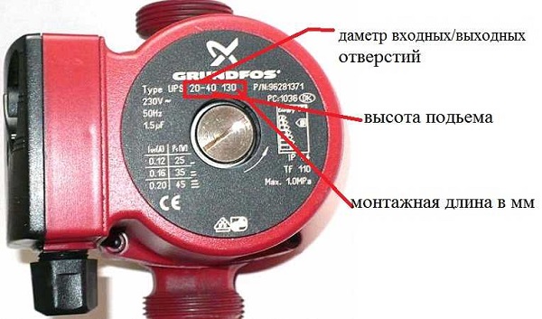
Pump marking
All user-relevant data is labeled on the front panel. The numbers on the circulation pump mean:
- type of device (most often it is UP - circulation);
- type of speed control (not specified - single-speed, S - step switching, E - smooth frequency control);
- nozzle diameter (indicated in millimeters, means the internal dimension of the pipe);
- head in decimeters or meters (may vary from manufacturer to manufacturer);
- mounting dimension.
The marking of the pump contains information about the types of connections of the inlet and outlet pipes. The complete coding scheme and word order looks like this:
Responsible manufacturers always follow standard labeling rules. However, individual companies may not indicate some of the data, for example, the installation dimension. You need to learn it directly from the documentation for the device.


It is worth choosing a pump only from trusted brands. Reliable devices are also presented in the middle price category
And if you need the highest quality and there is an opportunity to pay one and a half to two times more - you should pay attention to the products of the brands GRUNDOFS, WILO
Heat requirement of the room
When choosing a circulation pump, first of all, you need to proceed from the needs of the room for thermal energy. During the calculations, you need to rely on the amount of heat that is needed in the coldest months. It is recommended to entrust this work to professional designers who will be able to provide calculated indicators with high accuracy.
Self-calculation
When the consumer cannot use the services of specialists, it is necessary, based on the size of the room in need of heating, to calculate the approximate value of the pump power. If we consider the Moscow region, then, according to SNiP, for residential buildings with one and two floors, the recommended indicator of specific thermal power is 173 kW / m2, and for houses with three and four floors - 98 kW / m2. To determine the total amount of heat required, it is necessary to multiply these figures with the area of \u200b\u200bthe room.
The main types of pumps for heating
All equipment offered by manufacturers is divided into two large groups: "wet" or "dry" type pumps. Each type has its own advantages and disadvantages, which must be taken into account when choosing.
Wet equipment
Heating pumps, called "wet", differ from their counterparts in that their impeller and rotor are placed in a heat carrier. In this case, the electric motor is in a sealed box where moisture cannot get.
This option is an ideal solution for small country houses.Such devices are distinguished by their noiselessness and do not require thorough and frequent maintenance. In addition, they are easily repaired, adjusted and can be used with a stable or slightly changing level of water flow.
A distinctive feature of modern models of "wet" pumps is their ease of operation. Thanks to the presence of "smart" automation, you can increase productivity or switch the level of windings without any problems.
As for the disadvantages, the above category is characterized by low productivity. This minus is due to the impossibility of ensuring high tightness of the sleeve separating the heat carrier and the stator.
"Dry" variety of devices
This category of devices is characterized by the absence of direct contact of the rotor with the heated water it pumps. The entire working part of the equipment is separated from the electric motor by rubber protective rings.
The main feature of such heating equipment is high efficiency. But from this advantage follows a significant disadvantage in the form of high noise. The problem is solved by installing the unit in a separate room with good sound insulation.
When choosing, it is worth considering the fact that the “dry” type pump creates air turbulence, so small dust particles can rise, which will negatively affect the sealing elements and, accordingly, the tightness of the device.
Manufacturers solved this problem this way: when the equipment is operating, a thin water layer is created between the rubber rings.It performs the function of lubrication and prevents the destruction of sealing parts.
Devices, in turn, are divided into three subgroups:
- vertical;
- block;
- console.
The peculiarity of the first category is the vertical arrangement of the electric motor. Such equipment should be bought only if it is planned to pump a large amount of heat carrier. As for block pumps, they are installed on a flat concrete surface.
Block pumps are intended for use in industrial purposes, when large flow and pressure characteristics are required
Console devices are characterized by the location of the suction pipe on the outside of the cochlea, while the discharge pipe is located on the opposite side of the body.
The use of circulation pumps in home heating
Since some features of the operation of circulation pumps for water in various heating schemes have already been mentioned above, the main features of their organization should be touched upon in more detail. It is worth noting that in any case, the supercharger is placed on the return pipe, if home heating involves raising the liquid to the second floor, another copy of the supercharger is installed there.
closed system
The most important feature of a closed heating system is sealing. Here:
- the coolant does not come into contact with the air in the room;
- inside the sealed piping system, the pressure is higher than atmospheric pressure;
- the expansion tank is built according to the hydraulic compensator scheme, with a membrane and an air area that creates back pressure and compensates for the expansion of the coolant when heated.
The advantages of a closed heating system are many.This is the ability to carry out desalination of the coolant for zero sediment and scale on the boiler heat exchanger, and filling in antifreeze to prevent freezing, and the ability to use a wide range of compounds and substances for heat transfer, from a water-alcohol solution to machine oil.
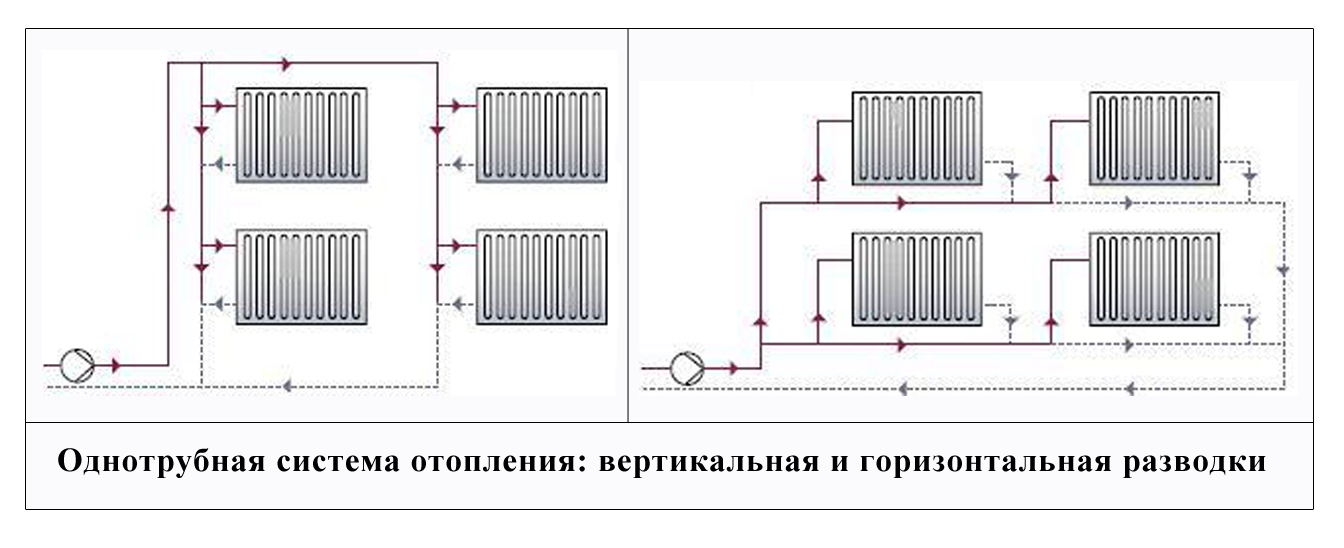
The scheme of a closed heating system with a single-pipe and two-pipe type pump is as follows:
When installing Mayevsky nuts on heating radiators, the circuit setting improves, a separate air exhaust system and fuses in front of the circulation pump are not needed.
Open heating system
The external characteristics of an open system are similar to a closed one: the same pipelines, heating radiators, expansion tank. But there are fundamental differences in the mechanics of work.

- The main driving force of the coolant is gravitational. Heated water rises up the accelerating pipe; to increase circulation, it is recommended to make it as long as possible.
- The supply and return pipes are placed at an angle.
- Expansion tank - open type. In it, the coolant is in contact with air.
- The pressure inside an open heating system is equal to atmospheric pressure.
- The circulation pump installed on the feed return acts as a circulation amplifier. Its task is also to compensate for the shortcomings of the pipeline system: excessive hydraulic resistance due to excessive joints and turns, violation of tilt angles, and so on.
An open heating system requires maintenance, in particular, a constant topping up of coolant to compensate for evaporation from an open tank.Also, corrosion processes are constantly taking place in the network of pipelines and radiators, due to which the water is saturated with abrasive particles, and it is recommended to install a circulation pump with a dry rotor.
The scheme of an open heating system is as follows:
An open heating system with the correct angles of inclination and a sufficient height of the accelerating pipe can also be operated when the power supply is turned off (the circulation pump stops working). To do this, a bypass is made in the pipeline structure. The heating scheme looks like this:
In the event of a power outage, it is enough to open the valve on the bypass bypass loop so that the system continues to work on the gravitational circulation circuit. This unit also makes the initial start-up of the heating easier.
Underfloor heating system
In the underfloor heating system, the correct calculation of the circulation pump and the choice of a reliable model are a guarantee of stable operation of the system. Without forced water injection, such a structure simply cannot work. The pump installation principle is as follows:
- hot water from the boiler is supplied to the inlet pipe, which is mixed through the mixer block with the return flow of the underfloor heating;
- the supply manifold for underfloor heating is connected to the pump outlet.
The distribution and control unit of the underfloor heating is as follows:
The system works according to the following principle.
- At the pump inlet, a main temperature controller is installed that controls the mixing unit. It can receive data from an external source, such as remote sensors in the room.
- Hot water of the set temperature enters the supply manifold and diverges through the floor heating network.
- The incoming return has a lower temperature than the supply from the boiler.
- The thermostat with the help of the mixer unit changes the proportions of the hot flow of the boiler and the cooled return.
- Water of the set temperature is supplied through the pump to the inlet distribution manifold of the underfloor heating.
As in practice, the hydraulic resistance of the heating system is considered.
Often engineers have to design heating systems for large facilities. They have a large number of heating devices and many hundreds of meters of pipes, but you still need to count. After all, without GR it will not be possible to choose the right circulation pump. In addition, GR allows you to determine whether all this will work before installation.
To simplify the life of designers, various numerical and software methods for determining hydraulic resistance have been developed. Let's start from manual to automatic.
Approximate formulas for calculating hydraulic resistance.
To determine the specific friction losses in the pipeline, the following approximate formula is used:
R = 5104 v1.9 /d1.32 Pa/m;
Here, an almost quadratic dependence on the velocity of the liquid in the pipeline is preserved. This formula is valid for speeds of 0.1-1.25 m/s.
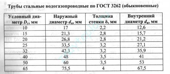
If you know the flow rate of the coolant, then there is an approximate formula for determining the inner diameter of the pipes:
d = 0.75√G mm;
Having received the result, you must use the following table to obtain the diameter of the conditional passage:
The most time-consuming will be the calculation of local resistances in fittings, valves and heating devices. Earlier I mentioned the coefficients of local resistance ξ, their choice is made according to the reference tables.If everything is clear with corners and stop valves, then the choice of KMS for tees turns into a whole adventure. To make it clear what I'm talking about, let's look at the following picture:
The picture shows that we have as many as 4 types of tees, each of which will have its own KMS of local resistance. The difficulty here will be in the correct choice of the direction of the coolant current. For those who really need it, I will give here a table with formulas from O.D. Samarin "Hydraulic calculations of engineering systems":
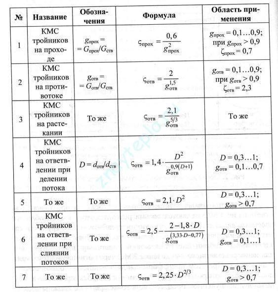
These formulas can be transferred to MathCAD or any other program and calculate the CMR with an error of up to 10%. The formulas are applicable for coolant velocities from 0.1 to 1.25 m/s and for pipes with a nominal diameter of up to 50 mm. Such formulas are quite suitable for heating cottages and private houses. Now let's look at some software solutions.


Programs for calculating hydraulic resistance in heating systems.
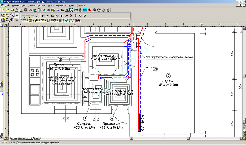
Now on the Internet you can find many different programs for calculating heating, paid and free. It is clear that paid programs have more powerful functionality than free ones and allow you to solve a wider range of tasks. It makes sense to acquire such programs for professional design engineers. A layman who wants to independently calculate the heating system in his house will be quite free programs. Below is a list of the most common software products:
- Valtec.PRG is a free program for calculating heating and water supply. It is possible to calculate underfloor heating and even warm walls
- HERZ is a whole family of programs. With their help, you can calculate both single-pipe and two-pipe heating systems.The program has a convenient graphical representation and the ability to break down into floor diagrams. It is possible to calculate heat losses
- Potok is a domestic development, which is a complex CAD system that can design engineering networks of any complexity. Unlike the previous ones, Potok is a paid program. Therefore, a simple layman is unlikely to use it. It is intended for professionals.
There are several other solutions as well. Mainly from manufacturers of pipes and fittings. Manufacturers sharpen calculation programs for their materials and thus, to some extent, force them to buy their materials. This is such a marketing ploy and there is nothing wrong with it.
Head of pumping equipment of circulation type
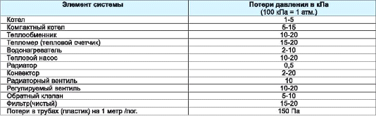
The pressure is created by the action of the pumping device in order to withstand the hydrodynamic losses that occur in pipes, radiators, valves, connections. In other words, pressure is the amount of hydraulic resistance that the unit must overcome. To ensure optimal conditions for pumping the coolant through the system, the hydraulic resistance index must be less than the pressure index. A weak water column will not be able to cope with the task, and too strong can cause noise in the system.
The calculation of the pressure indicator of the circulation pump requires a preliminary determination of the hydraulic resistance. The latter depends on the diameter of the pipeline, as well as the speed of movement of the coolant through it. To calculate hydraulic losses, you need to know the speed of the coolant: for polymer pipelines - 0.5-0.7 m / s, for pipes made of metal - 0.3-0.5 m / m.On straight sections of the pipeline, the hydraulic resistance index will be in the range of 100-150 Pa / m. The larger the pipe diameter, the lower the losses.
In this case, ζ denotes the coefficient of local losses, ρ is the heat carrier density index, V is the heat carrier displacement velocity (m/s).
Next, it is necessary to sum up the indicators of local resistances and the resistance values that were calculated for straight sections. The resulting value will correspond to the minimum allowable pump head. If the house has a highly branched heating system, the pressure should be calculated for each branch separately.
- boiler - 0.1-0.2;
- heat regulator - 0.5-1;
- mixer - 0.2-0.4.
At the same time, Hpu is the pump head, R is the losses that were caused by friction in the pipes (measured by Pa / m, the value of 100-150 Pa / m can be taken as a basis), L is the length of the return and direct pipelines of the longest branch or the sum of the width, length and height of the house multiplied by 2 (measured in meters), ZF is the coefficient for the thermostatic valve (1.7), fittings / fittings (1.3), 10000 is the conversion factor for units (m and Pa).
Conclusions and useful video on the topic
Rules for choosing circulation equipment in the video:
The subtleties of calculating the pressure and performance in the video clip:
Video about the device, the principle of operation and installation of the circulation pump:
A modern heat supply system with a built-in pump for forced circulation allows you to heat living quarters in a matter of minutes after starting the heat generator.
Rational selection of the circulation pump and high-quality installation significantly increase the efficiency of using boiler equipment by saving energy resources by about 30-35%.
Are you looking for a circulation pump for your heating system? Or do you have experience with these setups? Please share your experience with readers, ask questions and participate in discussions. The comment form is located below.