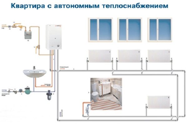
- Scheme of hot water supply and heating
- Pipe selection
- 1 The role of the device in wiring and its features
- Materials for manufacturing
- Polypropylene knot
- Advantages of a polypropylene device
- From brass fittings
- From a profile pipe
- Accessories and rules for soldering polypropylene pipes
- Self-brazing polypropylene pipes
- Kinds
- Collector group for heating system assy
- Comb - manifold assembly
- Manifold block installation
- Most wanted models
- Conclusions and useful video on the topic
Scheme of hot water supply and heating
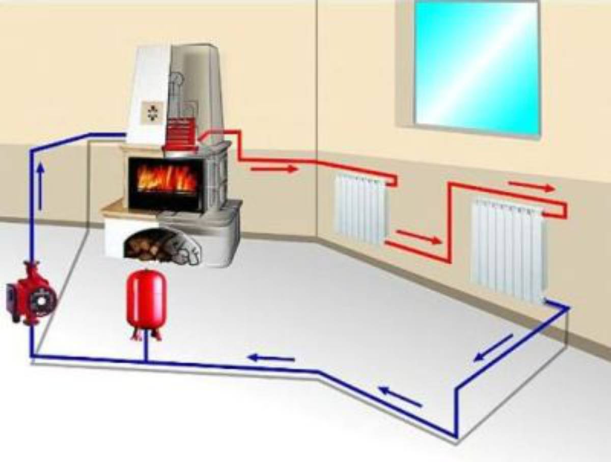
If you want to ensure the operation of both heating and hot water supply, you need to combine the two options discussed earlier into one scheme. To solve the problem, you will need to use a boiler with an additional capacity, equipped with a coil for circulating the coolant. In the inner smaller tank, the liquid heats up much faster. At the same time, it will give off heat to a common container of large dimensions.
The boiler must be connected to another heat source. All types of boilers are suitable for this purpose. They can be electric, gas or solid fuel.
The solar battery provides unstable heating of the coolant. This can lead to rapid cooling of the liquid or vice versa to its overheating.To avoid this, you need to use automation that will control the temperature in the circuit.
We figured out the methods of tying circuits based on solar collectors. Therefore, now let's go directly to the methods of self-manufacturing them.
Pipe selection
Before starting work directly related to the creation of a heat supply system, it is required to coordinate the main parameters of pipelines. First of all, the source of thermal energy, the inlets and outlets to the collector, as well as the pipeline must be of the same diameter. Otherwise, when using pipes of different diameters, adapters are used. Their installation requires additional material costs and time for installation.

Failure to comply with the required diameters for pipes leads to such negative consequences as:
- violation of the circulation of the coolant;
- airing the heating circuit;
- uneven heating.
1 The role of the device in wiring and its features
Heating systems made according to schemes that allow significant savings on pipes and valves do not have sufficient efficiency. In conditions of a significant increase in the cost of heat carriers, their use is expensive for consumers. Piping to radiators using a manifold will change the position. There will be no excessive consumption of fuel, the heating of each device is regulated.
The system acquires new functionality: increased safety and suitability for repair. Now, to fix a leak, you do not need to turn off the entire system and drain the water. The branch is blocked, the malfunction is eliminated, and the heating in the remaining rooms continues to work.
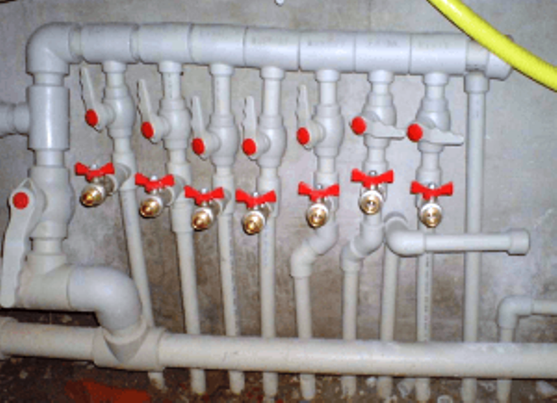
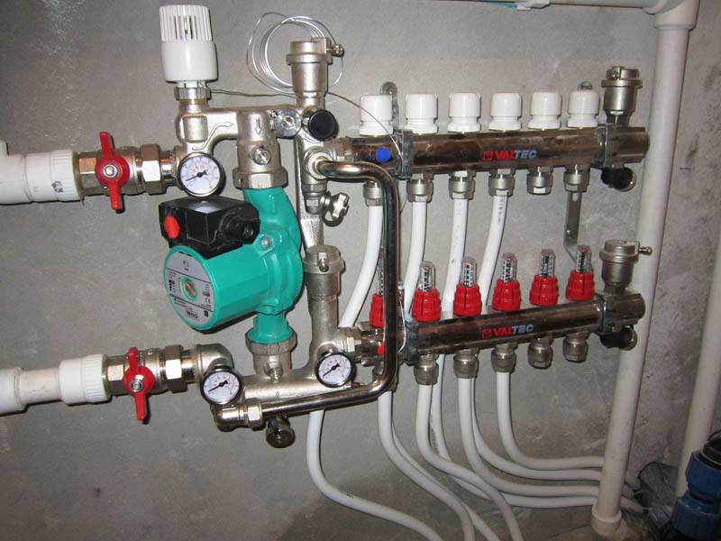
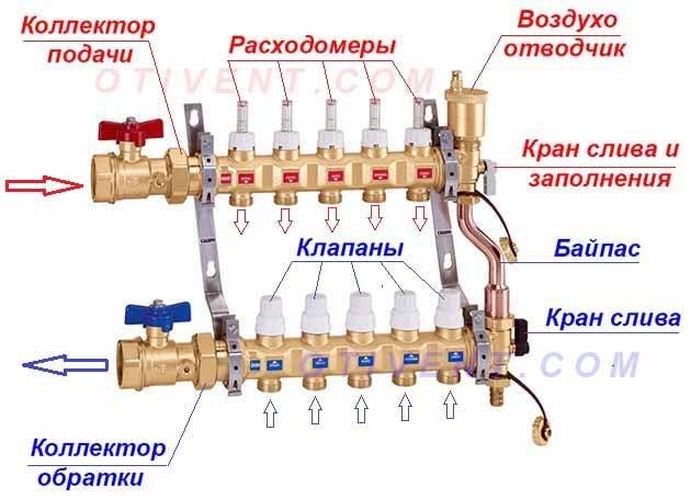
A collector, which is also called a comb, is a cylindrical part that has one input and outputs connecting it to devices. The dimensions are not limited by anything and depend on the number of connected heating devices. Shut-off valves are installed on the pipes, which regulate the supply of coolant for each individual circuit. There are two types of valves. Shut-off ball valves are usually used to shut off sections. As adjusting they are unsuitable, a different type is required.
The work is carried out according to the following principle: the coolant under forced pressure enters the device. From here it is distributed through the bends to the radiators, the warm floor. A collector circuit is used (also called a beam circuit), the essence of which is the parallel connection of consumers. Each has its own supply line and return line, which are equipped with fittings. Even with the simultaneous inclusion of all devices, the heating is uniform.
A circulation pump is used to create a forced pressure. It is selected based on the area and number of storeys of the house. If the system has a warm floor, more performance is required, because it creates increased resistance. The temperature difference at the inlet and outlet is reduced, the heating is of better quality. Thermostats can be used instead of control taps, which guarantees precise heat supply. If the pipes are placed under the screed, an air valve is installed on each device.
Collectors are used with a variety of systems:
- 1. Heating with radiators. They use various connection schemes, but usually the lower one with polypropylene pipes, which are hidden under the coating or skirting boards.
- 2. Warm water floor.It is mainly used as an auxiliary.
- 3. Solar heating. In clear weather, it is possible to obtain 10 kW / hour of energy from one square meter of the device.
With beam wiring, the temperature in each circuit is regulated separately, for which the desired indicators are set on the thermostat. In the garage, 10 ° is enough, in the nursery, at least 20 ° is required, and for a warm floor - no more than 35 °, otherwise it will be unpleasant to walk on it, and the coating may be deformed. In houses with several levels, the comb is mounted on each floor.
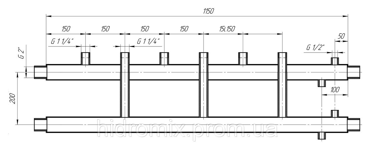
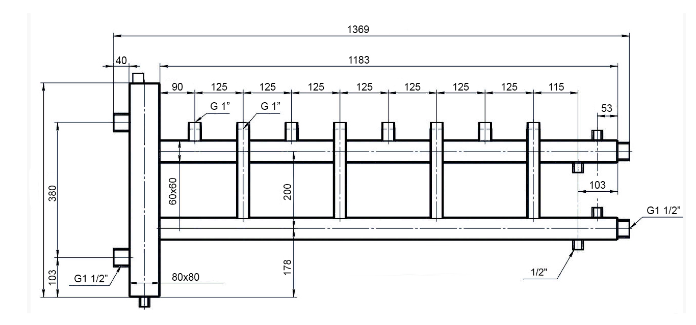
Materials for manufacturing
For the manufacture of the collector assembly, pipes can be used: metal (round and rectangular) or polypropylene. The connection of the outlet circuits with the collector pipe is made through ball or valve valves, with the help of which the supply of coolant to each section of the heating system is regulated.
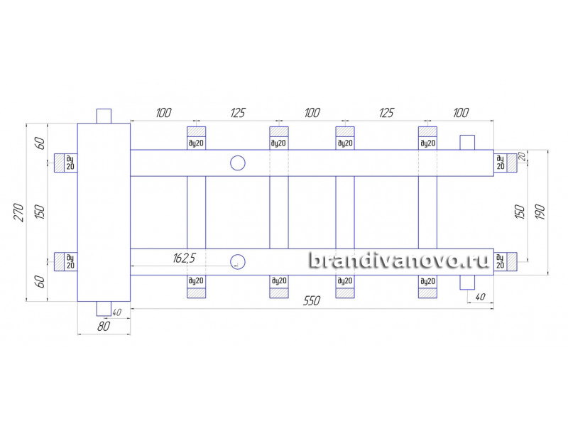
Polypropylene knot
For this, pieces of a polypropylene pipe are used, for example, with a diameter of 32 mm (remains from the construction of the heating system of the house can be) and several fittings in the form of tees with dimensions of 32/32/32 - it is installed at the end of the collector assembly, and 32/32/16 - intermediate elements for connection with outlet channels by sections.
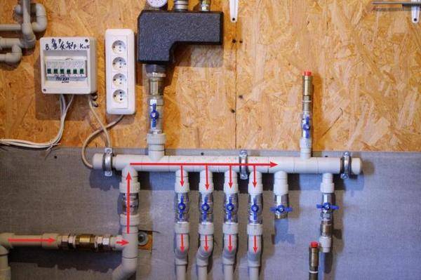
Photo 1. A manifold for a heating system made of polypropylene. The red lines indicate the coolant flow.

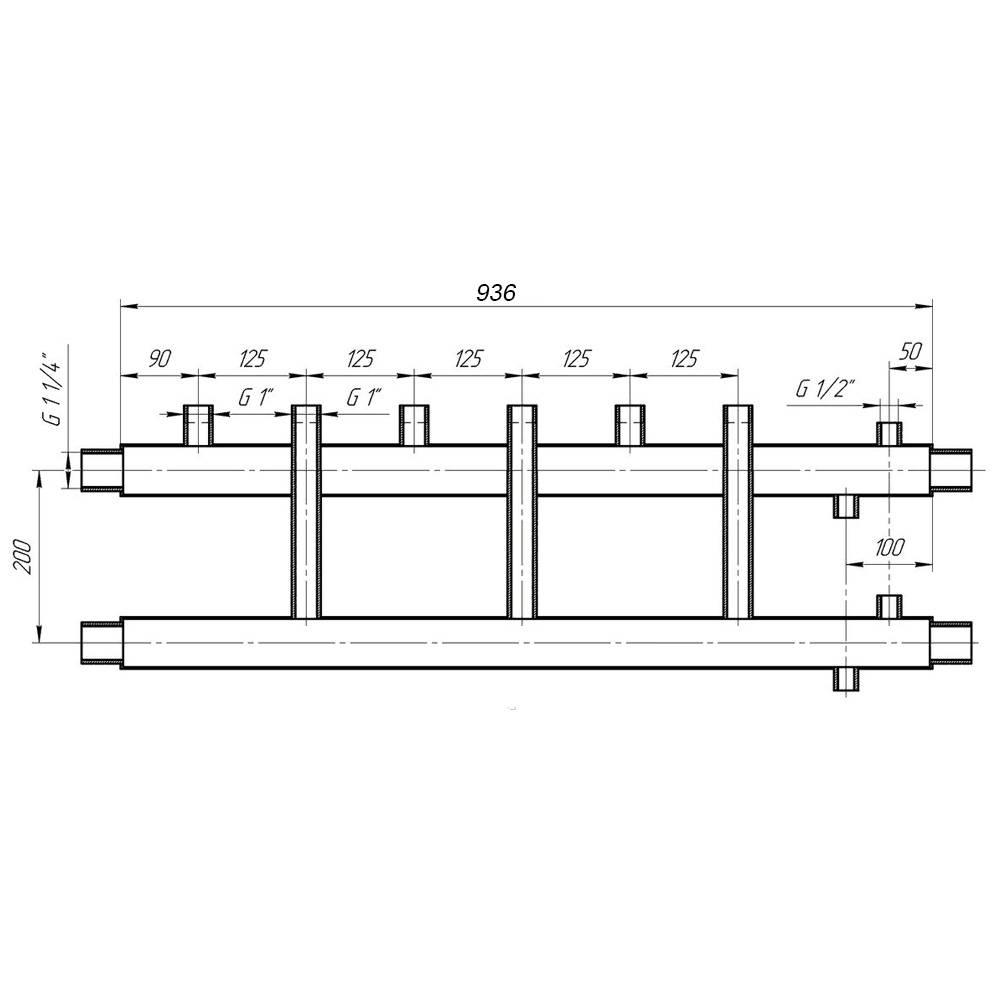


The first tee is mounted perpendicular to the main pipe. Its two outer pipes, located vertically, are connected as follows: an air vent is connected to the upper one, and a drain valve is connected to the lower one. A valve or ball valve is mounted to the opposite end of the collector installation. A pipe will go from it towards the boiler.
Intermediate tees are connected into one structure, which will be called a manifold. Therefore, a collector installation is first assembled by welding 32/32/16 tees with pieces of 32 mm pipes, after which a 32/32/32 tee is installed and a tap on the opposite side. Next, taps or valves on 16 mm branch pipes are attached to the intermediate fittings. It is with their help that the adjustment of the coolant supply to each circuit will be carried out.
Advantages of a polypropylene device
First of all, it should be noted that the design is cheap, because for this you only have to purchase a small number of tees and taps. Other advantages:
- if you correctly carry out welding, then such a design will not leak;
- polypropylene is not subject to corrosion, does not rot and does not change its characteristics under the influence of water and high temperatures;
- small weight of the device;
- ease of installation.
From brass fittings
To assemble such an installation, brass fittings and valves are used.
To do this, it is necessary to connect the same tees with double-sided couplings by means of a threaded connection with the obligatory winding of the sealing material on the thread.
At the same time, if the thread on the tees is internal (which is most often found), then the couplings must be with external thread and clamping nuts.
The number of tees is the number of circuits, plus one. The latter is installed at the end of the collector and is connected by two pipes to a drain cock and an air vent.
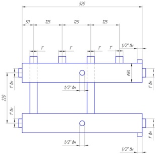
From a profile pipe
This is the most complex process associated with welding work on metal.Skills and experience are required here, because welding of two pipes requires complete welding of the joint throughout the entire thickness of the products being joined.
Previously, it is recommended to sketch a sketch on paper with an exact definition of the location of the nozzles. Spurs with a diameter corresponding to the dimensions of the pipes of the discharge circuits are taken as branch pipes. The parameters on paper are transferred to profiled pipes used as a collector. Their cross section is either 80x80 or 100x100 mm.
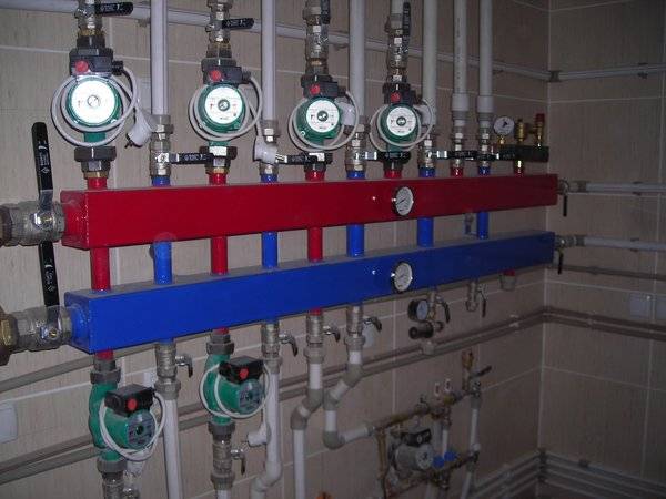
Photo 2. A heating manifold made of shaped pipes. Red indicates hot coolant, blue indicates cold.
On them, on the one hand, the locations of the nozzles are applied with the exact designation of the outer diameter. After that, holes are cut out with a gas cutter or plasma cutter. Drives are welded to them strictly perpendicularly. At one end, a large pipe is closed with a metal plug (attachment is made by electric welding).
On the other side, the same plug is installed, in which a hole is pre-cut for connection with a valve or faucet. That is, a drive cuts into the hole. Places of welding must be cleaned with a metal brush from scale.
Two such elements are connected into one structure by installing metal profiles between them. One is connected to the coolant supply circuit, the second to the return circuit. It is better if you mark different groups with different colors: red is used for supply, blue for return.
Accessories and rules for soldering polypropylene pipes
Types of fittings for polypropylene pipes
The connection of polymer pipes can be performed in several ways - soldering, detachable or one-piece fittings, gluing.Diffusion welding is best for installing water heating with your own hands from polypropylene. The main connecting element in this case are the fittings.


It is important that the quality of the purchased components is not inferior to the pipes. All fittings for pipes made of polypropylene for heating do not have reinforcement. This is offset by a thicker wall
They differ in appearance and scope:
This is compensated by a thicker wall. They differ in appearance and scope:
- Couplings. Designed to connect individual pipes into a single line. They can be both of the same diameter, and transitional for joining pipelines with a spill section;
- corners. Scope - production of corner sections of highways;
- Tees and crosses. Necessary for dividing the highway into several separate circuits. With their help, a collector for heating is made of polypropylene;
- Compensators. Hot water provokes thermal expansion of pipelines. Therefore, before soldering heating from polypropylene, compensation loops should be installed that prevent surface tension from appearing in the line.
Before starting the soldering process, it is recommended to calculate the amount of all consumables: pipes, fittings and valves. For this, a heat supply scheme is drawn up indicating the configuration of each node.
During the installation of polypropylene heating, it is necessary to use a special type of shut-off valves designed for soldering.
Self-brazing polypropylene pipes
A set of tools for soldering polypropylene pipes
In order to make heating from polypropylene, you should purchase a minimum set of tools.It includes a soldering iron for pipes, special scissors and a trimmer. The latter is necessary for stripping the pipes from the reinforcing layer in the soldering area.
Before soldering heating from polypropylene, the required pipe size should be cut off. For this, special scissors with a base for the nozzle are designed. They will provide an even cut without distortion.
For self-installation of heating from polypropylene, you will need to perform the following steps:
- Degrease the soldering point on the nozzles.
- Using a trimmer, remove the reinforcing layer from the heating zone.
- Turn on the soldering iron and set it to a certain temperature.
- After heating the mirror, install the nozzle and the coupling into the nozzles. It is impossible to make axial rotations during heating of polypropylene.
- After a certain period of time, dock the branch pipe and the coupling with each other.
- Wait for the final cooling.
The procedure for soldering polypropylene pipes
Using this technology, you can make a reliable heating system from polypropylene with your own hands. The advantage of this method lies in the possibility of soldering on already mounted sections of the trunk. In this way, you can quickly repair the heating of a private house with your own hands from polypropylene.
An important point during the self-soldering of water heating from polypropylene is the heating time of the workpieces. It depends on the pipe diameter and wall thickness. With insufficient melting of the material, the diffusion process will be low, which will eventually lead to delamination of the joint. If the pipe and the coupling are overheated, a part of the material will evaporate, and as a result, a strong decrease in the external dimensions will occur.Therefore, for the installation of heating from polypropylene, one should adhere to the recommended heating time for plastic, depending on its diameter and wall thickness.
Table for soldering polypropylene pipes
During self-installation of polypropylene with your own hands, good ventilation in the room is necessary. When plastic evaporates, its volatile components can enter the respiratory system.


For a small amount of work, you can purchase a non-professional soldering iron worth up to 600 rubles. With it, you can solder a polypropylene heating system for a small house or apartment.
Kinds
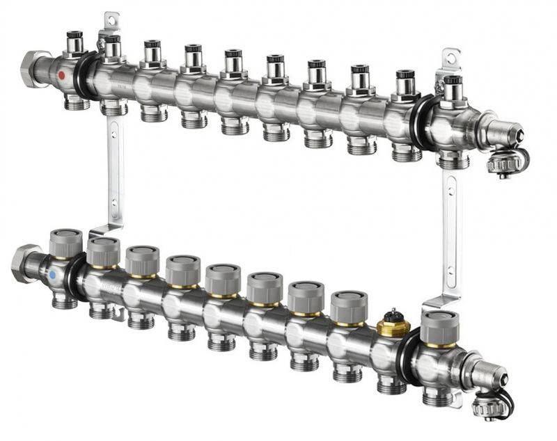
Collector groups for heating systems are sold in finished form, while they may have a different configuration and number of branches. You can choose a suitable collector assembly and install it yourself or with the help of specialists.
However, most industrial models are universal and do not always fit the needs of a particular home. Their alteration or refinement can significantly increase costs. Therefore, in most cases it is easier to assemble it from separate blocks with your own hands, taking into account the features of a particular heating system.
Collector group for heating system assy
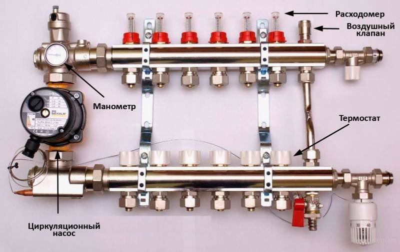
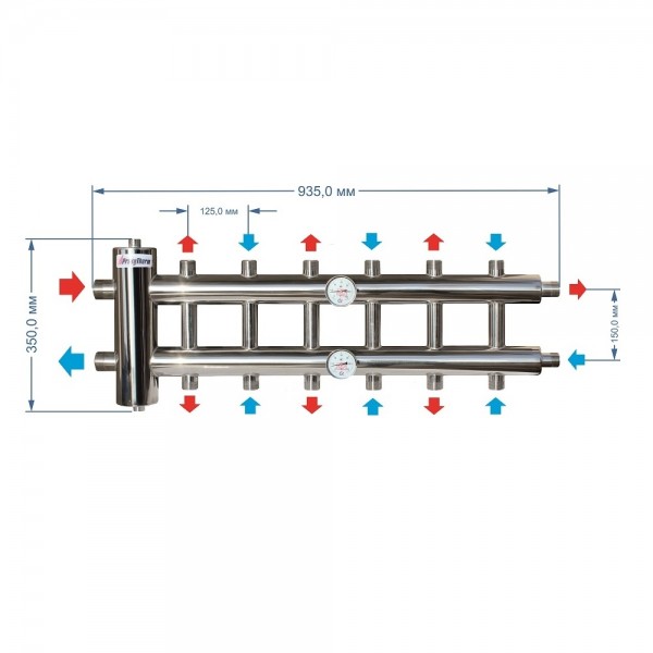
The design of the universal manifold group is shown in the figure. It consists of two blocks for direct and reverse flow of the coolant, equipped with the required number of taps. Flowmeters are installed on the supply (direct) manifold, and thermal heads are located on the return manifold to control the temperature of the return water in each circuit. With their help, you can set the required flow rate of the coolant, which will determine the temperature in the heating radiators.
The manifold distribution unit is equipped with a pressure gauge, circulation pump and air valves. The supply and return manifolds are combined into one unit with brackets, which also serve to fix the unit to a wall or cabinet. The price of such a block is from 15 to 20 thousand rubles, and if some of the branches are not used, its installation will be clearly inappropriate.
The rules for mounting the finished block are shown in the video.
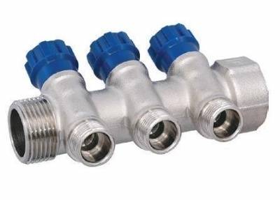
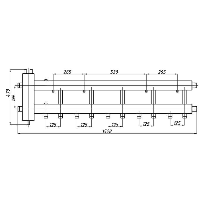
Comb - manifold assembly
The most expensive elements in the manifold distribution block are flow meters and thermal heads. To avoid overpaying for extra elements, you can buy a collector assembly, the so-called "comb", and install the necessary control devices with your own hands only where necessary.
The comb is a brass tube with a diameter of 1 or ¾ inches with a certain number of branches with a diameter for heating pipes ½ inch. They are also connected to each other by a bracket. The outlets on the return manifold are equipped with plugs that allow you to install thermal heads on all or part of the circuits.
Some models can be equipped with taps, with their help you can adjust the flow manually. Such combs have a cast body and are equipped with a fitting / nut thread at the ends, which allows you to quickly and easily assemble a manifold from the required number of taps.
In order to save money, the collector for heating systems can be assembled from individual elements on your own or completely done by yourself.
Manifold block installation
Installation of the collector for the boiler is carried out as close as possible to the boiler. Pipes are laid on the floor surface, after which they are filled with a tightening compound and insulated. This method allows minimizing the loss of thermal energy.The block is located in a special niche or shield. In a high-rise building, such a system will be installed on each floor, which will allow heating any room.
 Mounted block.
The coplanar collector for the boiler evenly distributes heat over the entire floor area. The cooled liquid returns, mixes with the hot one and goes to the next circle. The device is used with hot and cold water, as well as with a glycol solution.
When installing the collector, the following requirements must be observed:
- installation of a pump and expansion tank;
- purchase of additional elements of pipeline and automation;
- installation of collector groups in metal boxes;
- decorating the structure;
- selection of premises (pantry, corridor);
- passing pipes through holes in the walls of the box.
This work is best left to a professional. The most effective heating option is considered to be the connection of the underfloor heating collector to the boiler (gas). Such nodes allow you to reduce the cost of utility bills, since electricity is much more expensive. Floor standing boilers for diesel fuel are used as alternative energy sources.
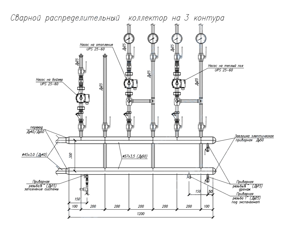
Types of connection of two boilers or more:
- Parallel. The water supply circuits are connected to 1 line, and the return circuits to the other.
- Cascade (sequential). Assumes a thermal load balance across multiple units. Before connecting the system, it is recommended to install special controllers. Boiler piping is only possible with these devices.
- According to the scheme of primary-secondary rings. In the first of them, water constantly circulates. The secondary ring in this scheme will be each circuit and the boiler itself.
Devices can be purchased at the store or made independently.To do this, you will need to carry out calculations and develop a wiring project. As a material, it is best to use steel pipes with a square section. When using polypropylene raw materials, it is worth making sure that there is a reinforced layer, since the product undergoes deformation under the influence of high temperature.


Properly selected parts will help make the design more reliable and durable. In the absence of the necessary tools, it is recommended to assemble the comb from finished parts. It is best to purchase components from 1 manufacturer. A homemade device will cost the creator several times cheaper than buying a finished device. Factory models often contain unnecessary elements.
Most wanted models
1. Oventrop Multidis SF.
The inch comb of heating is intended for the organization of heating by a water heat-insulated floor. Manufactured from high wear resistant tool steel. Main characteristics:
- allowable pressure in the circuit - 6 bar;
- coolant temperature - +70 °С.
The series is produced with M30x1.5 valve inserts, and can also be equipped with a flow meter for connecting circuits located in different rooms. Bonus from the manufacturer - soundproof mounting clamps. The number of simultaneously serviced branches is from 2 to 12. The price, respectively, is 5650-18800 rubles.
To work with high-temperature appliances, Oventrop suggests using the distribution manifold of the Multidis SH stainless steel heating system with a Mayevsky tap. The design already withstands 10 bar at + 95-100 ° C, the throughput of the comb is 1-4 l / min.However, for products with 2 circuits, the indicators are slightly weaker. The cost of Oventrop SH hydrodistributors fluctuates in the range of 2780-9980 rubles.
Plumbers: You'll pay up to 50% LESS for water with this faucet attachment
- HKV - brass manifold for underfloor heating. Holds a pressure of 6 bar in the range of + 80-95 ° С. Rehau version D is additionally equipped with a rotameter and a tap for filling the system.
- HLV is a heating distribution manifold designed for radiators, although its characteristics are identical to those of HKV. The only difference is in the configuration: there is already a Eurocone and the possibility of a threaded connection with pipes.
Also, the manufacturer Rehau offers to buy separate Rautitan combs with three exits for pipeline installation using compression sleeves.
Distribution collector of heating from steel with an anticorrosive covering. It works in systems with temperatures up to +110 °C at a pressure of 6 bar and hides in a special heat-insulating casing. The capacity of the comb channels is 3 m3/h. Here, the choice of designs is not too rich: only 3 to 7 circuits can be connected. The cost of such hydraulic distributors will be from 15,340 to 252,650 rubles.
Stainless steel manifolds are produced in an even more modest assortment - for 2 or 3 circuits. With the same characteristics, they can be purchased for 19670-24940 rubles. The most functional Meibes line is the RW series, which already comes with various connecting elements, thermostats and manual valves.
- F - a flow meter is built into the supply;
- BV - has quarter taps;
- C - provides for building a comb through a nipple connection.
Each Danfoss heating manifold allows a pressure in the system of 10 atm at the optimum temperature (+90 °C). The design of the brackets is interesting - they fix the paired combs with a slight offset relative to each other for more convenient maintenance. At the same time, all valves are equipped with plastic heads with printed markings, which allows you to set their position manually without the use of tools. The price of Danfoss models, depending on the number of connected circuits and additional options, varies between 5170 - 31,390.
The heating manifold can be selected for a euro cone with 1/2″ or 3/4″ outlets or with a metric threaded connection. Far combs withstand pressure up to 10 atm at temperatures not exceeding +100 °C. But the number of outlet pipes is small: from 2 to 4, but the price is the lowest of all the products considered in our review (730-1700 rubles for an unpaired distributor).
Selection Tips
Despite the seeming simplicity of the combs, they need to be selected based on several technical parameters at once:
1. Head in the system - this value determines what material the distribution manifold can be made of.
2. The throughput must be sufficient so that the connected heating circuits do not “starve” from a lack of coolant.


3. Energy consumption of the mixing unit - as a rule, it is determined by the total power of the circulation pumps.
4
The ability to add contours - this parameter should be paid attention only when it is planned to build additional objects in the future that need heating
The number of nozzles on the hydraulic distributor must correspond to the number of connected branches (heaters).In some cases, it is better to install several collectors, for example, in a two-story house - one block at each level. It is also allowed to install unpaired combs at different points: one on the supply, the other on the return.
Finally, experts and experienced installers in their reviews advise not to save on buying a good collector. In order for it to serve for a long time and not cause any special problems, the name on the box must be known.
Conclusions and useful video on the topic
How to properly install:
By installing a collector heating system in your home, you will be able to individually adjust the operating modes of the devices.
And the additional costs of increasing the length of the pipes are compensated by reducing their diameter and simplifying the installation of the system.
Do you have a collector heating system at home? Or are you just planning to equip it, but for now you are studying the information? Maybe you have a question about drawing up a wiring diagram for a collector system? Ask your questions, share your personal experience in arranging heating in the house, leaving comments under this article.