- Modifications of distribution manifolds
- Manifold block installation
- What is a collection group for?
- Installation of a distribution manifold
- Radiant heating system optimal solution
- What are air vents and what are they for?
- Calculation of the throughput of the combs
- Installing the collector in the heating system
- The principle of operation of the distribution comb for heating
- Setting up a comb for underfloor heating
- Design features of a warm floor without a mixing unit
- Compalan distribution manifold
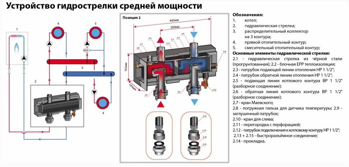
- Heating distribution manifold device
- Installation features and cost
- What is a comb for?
- Comb for heating, distribution manifold.
Modifications of distribution manifolds
Today on the market there are many types of collector devices designed for heating systems. You can find ordinary connecting links in which there are no auxiliary valves. There are also complex blocks with many additional elements.
The simplest instruments are made of brass and have inch holes. On the reverse side, they have plugs that can be used to expand the system and build additional secondary devices.
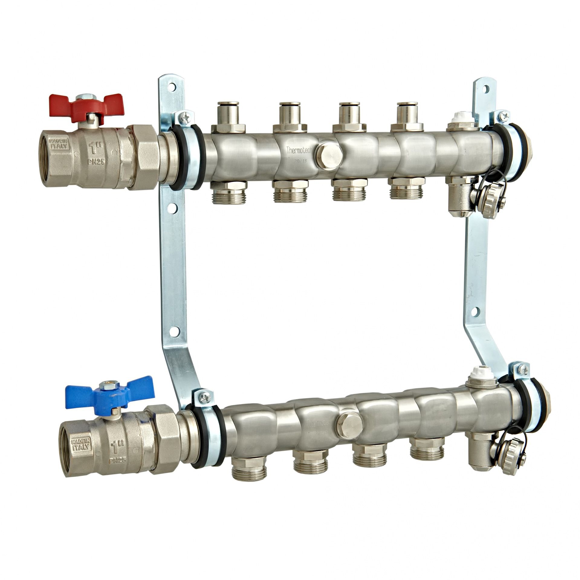
Mechanisms with a more complex design have nodes that are equipped with ball valves. A shut-off valve is installed on each outlet element. More expensive devices may have:
- Flowmeters. They are necessary to regulate the flow of heat carrier for each individual loop.
- Electronic valves. Their purpose is to maintain the required temperature.
- Thermal sensors.
- Valves for automatic removal of air from system.
The number of circuits can vary from 2 to 10. It all depends on consumers. Intermediate manifolds can be made of brass, stainless steel, polypropylene. Most often choose polypropylene, as they are the cheapest.
Manifold block installation
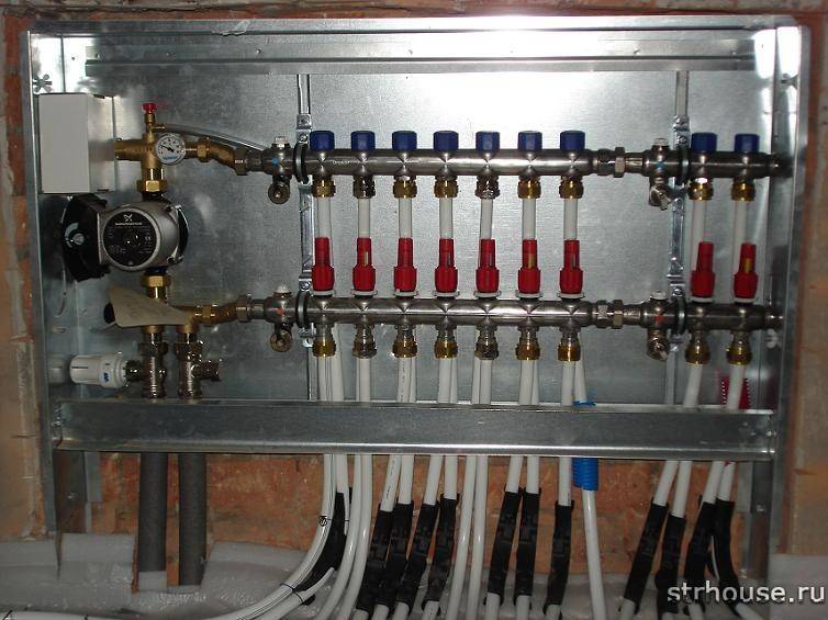
Installation of the collector for the boiler is carried out as close as possible to the boiler. Pipes are laid on the floor surface, after which they are filled with a tightening compound and insulated. This method allows minimizing the loss of thermal energy. The block is located in a special niche or shield. In a high-rise building, such a system will be installed on each floor, which will allow heating any room.
Mounted block.
The coplanar collector for the boiler evenly distributes heat over the entire floor area. The cooled liquid returns, mixes with the hot one and goes to the next circle. The device is used with hot and cold water, as well as with a glycol solution.
When installing the collector, the following requirements must be observed:
- installation of a pump and expansion tank;
- purchase of additional elements of pipeline and automation;
- installation of collector groups in metal boxes;
- decorating the structure;
- selection of premises (pantry, corridor);
- passing pipes through holes in the walls of the box.
This work is best left to a professional. The most effective heating option is considered to be the connection of the underfloor heating collector to the boiler (gas). Such nodes allow you to reduce the cost of utility bills, since electricity is much more expensive. Floor standing boilers for diesel fuel are used as alternative energy sources.
Types of connection of two boilers or more:
- Parallel. The water supply circuits are connected to 1 line, and the return circuits to the other.
- Cascade (sequential). Assumes a thermal load balance across multiple units. Before connecting the system, it is recommended to install special controllers. Boiler piping is only possible with these devices.
- According to the scheme of primary-secondary rings. In the first of them, water constantly circulates. The secondary ring in this scheme will be each circuit and the boiler itself.
Devices can be purchased at the store or made independently. To do this, you will need to carry out calculations and develop a wiring project. As a material, it is best to use steel pipes with a square section. When using polypropylene raw materials, it is worth making sure that there is a reinforced layer, since the product undergoes deformation under the influence of high temperature.
Properly selected parts will help make the design more reliable and durable. In the absence of the necessary tools, it is recommended to assemble the comb from finished parts. It is best to purchase components from 1 manufacturer. A homemade device will cost the creator several times cheaper than buying a finished device.Factory models often contain unnecessary elements.
What is a collection group for?
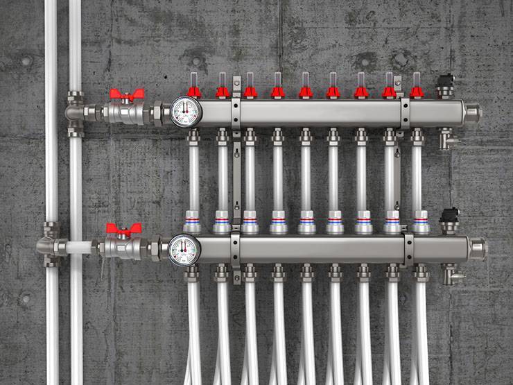
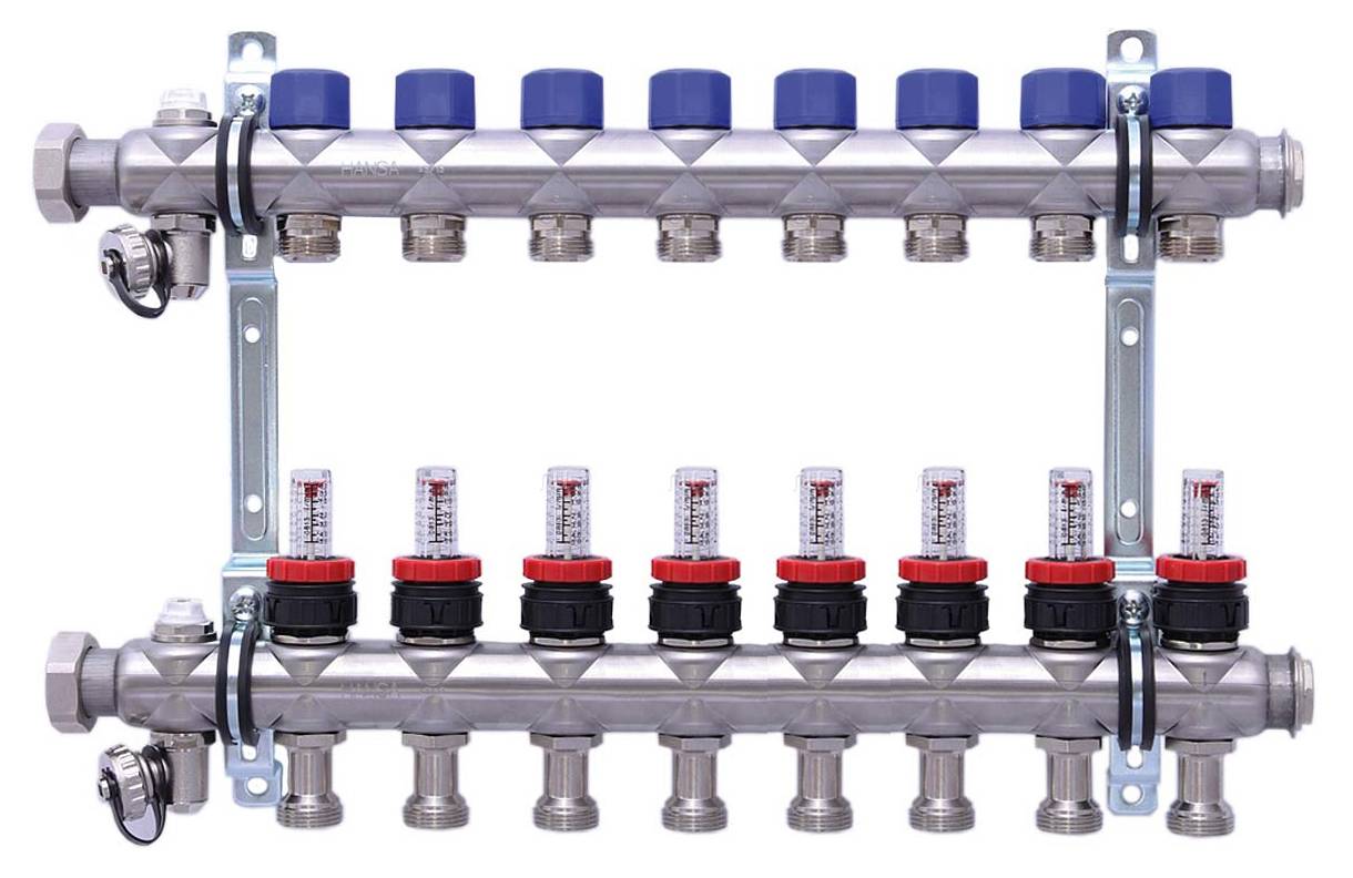
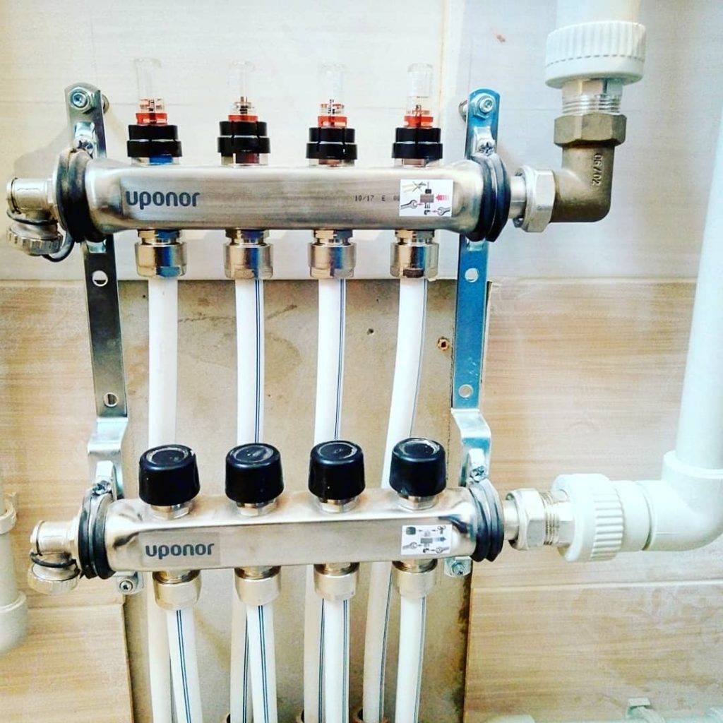
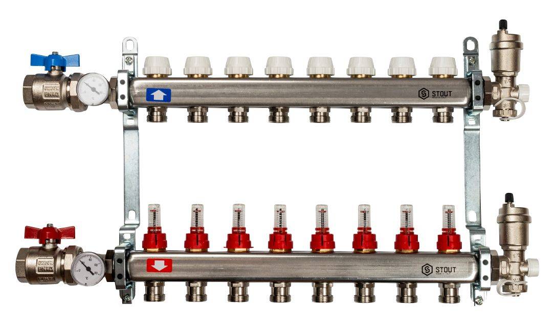
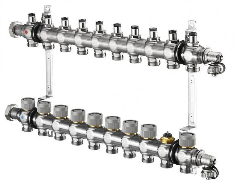
The heating distribution manifold looks like a metal comb, as it has a large number of leads for connecting heating devices. This allows you to adjust the volume, temperature and pressure of the coolant. Therefore, with the help of the device, it is possible to control the heat supply in each individual room of a house or apartment. Radiators, convectors, underfloor heating systems and even panel heating can be connected to the distribution manifold. Nowadays, the collector heating system is quite popular.
It is important to understand why a collector is needed in heating.
Most Russian consumers use collectors of the European STOUT brand, as they are more suitable for work in Russia. Manufacture of collectors is carried out at the Italian factories. The use of high-tech equipment and strict quality control at each production stage allows us to obtain high quality products.
Compared to premium brands, which are also produced in factories in Italy, STOUN collectors are cheaper.
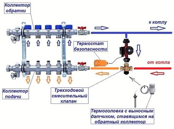
For most consumers, the actual question is how the heating collector works. A feature of the device are two interconnected parts, the supply and return manifold, combined into one unit. The first component controls the supply of hot water to each heating device, while using a special valve, each active circuit is closed if necessary.The return collector distributes the heat and regulates the pressure level, which contributes to the proportional heating of each room in the house.
Installation of a distribution manifold
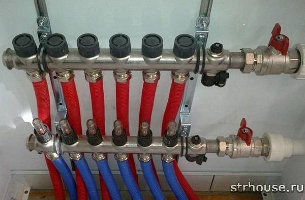
Mounting the comb does not portend an easy job. As a rule, it takes a lot of time and requires the hands of a specialist who knows a lot about this matter. But, despite all the difficulties of installation, they try to install exactly this wiring in modern houses and apartments, since it is very effective and easy to use. New models of combs are produced taking into account the complexity of installation, this greatly facilitates the work of the master during installation. You can mount it not only in the cabinet, but also to the wall for this, the kit includes mounting clamps for greater stability of the device, and high resistance to corrosion allows the comb to serve for many years.


In order to clearly understand what a distribution comb is, you need to know about it all the information necessary for a person who does not understand anything in this matter. For a complete acquaintance, it is worth introducing several types of different combs.
Manufacturing materials can be polymer, steel, brass or copper.
Configuration:
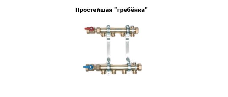
Simple - are deprived of an important quality - control of coolant flows. Such combs divide the total water flow by the number of nodes present in the house, they bring a uniform flow to the bathroom, kitchen, toilet and other places where water goes. The design of the comb is the simplest - a couple with special connections on both sides and branches in the amount of 2, 3 or 4 pieces
The design of the comb is the simplest - a couple with special connections on both sides and branches in the amount of 2, 3 or 4 pieces.
Complex - have many useful additional elements: pipeline fittings; control and accounting sensor; automation. Temperature sensors or, as they are also called, thermal sensors are installed in combs with an electronic or mechanical system. They are in complete control flow and supply of water pipes are especially convenient when a coolant is connected.
Radiant heating system optimal solution
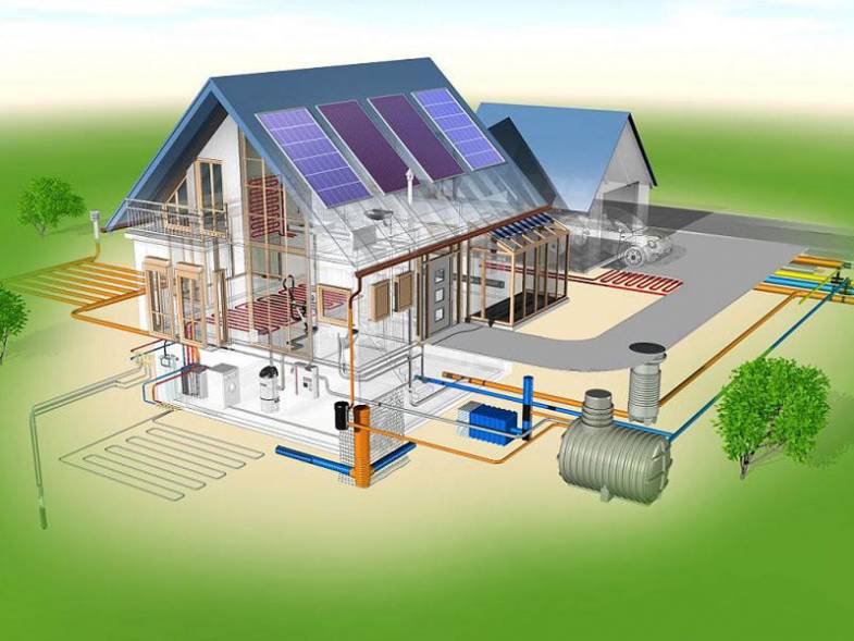
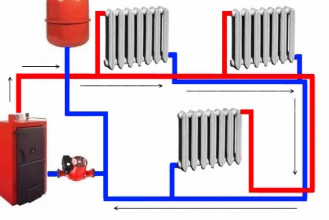
Diagram of a radiant heating system.
Anyone who owns their own home naturally wants to organize an optimal system of good heating with their own hands. He must know for sure: the ideal heating system has not yet been invented, therefore it is necessary to choose what is most practical and has received positive approval. The heating system, nicknamed radiant, can be given preference. Its romantic-geometric name is quite understandable: every radiator has its own beam as a pipeline.
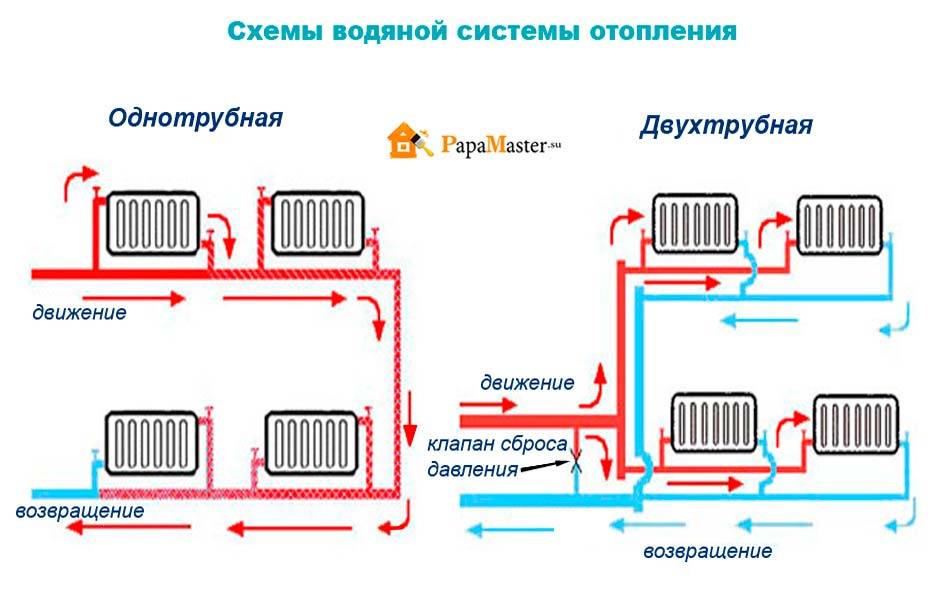
If the owner owns a cozy, not very massive house, consisting of two floors, then the scheme for constructing a heating system using collectors implies the presence of a collector on each floor. They are combined in a parallel way, then they put the boiler, then the expansion tank. This heating system is sometimes called a two-pipe system. And it is right. A pair of pipelines runs through all the rooms that need to be heated. One line of pipes is created for the direct movement of the fluid - the coolant, the other is responsible for the way back.
What are air vents and what are they for?
Many owners of radiator systems have encountered a situation where, with hot pipes, some parts of the radiator do not heat well or they are generally cold, similar problems arise with warming with water floors. The main reason for this phenomenon is the presence of air in the pipes, which rises and prevents the movement of the heat carrier.
If in an open circuit air bubbles are sent to an unclosed expansion tank located on high floors of a building or an attic, and bleed is not so important, then in a closed system an air vent of the heating system is vital on all circuits and individual heat exchangers.
When plugs interfere with the system, manual or automatic heating bleed valves are used to remove accumulated air. One of the simplest devices is a conventional valve installed at the top of heating radiators. To release air from the batteries, the valve is opened and they wait for the moment when the jet stops flowing jerkily along with air - in radiators without air, the water flow will be uniform.
In individual heating lines of private houses, instead of ordinary valves, special locks are installed on radiators, which operate automatically or are manually adjusted. With their help, not only air is removed from devices in which gas formation occurs, but also, when necessary, oxygen from water, which causes accelerated corrosion of metal fittings.
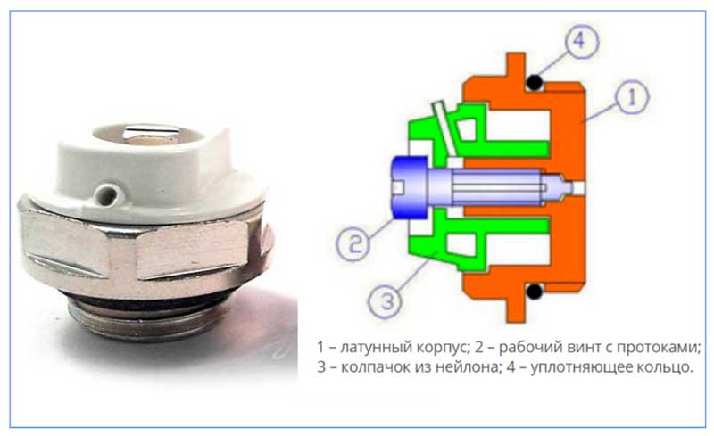
Rice. 2 Air vent for venting air from the heating system - design
Calculation of the throughput of the combs
The calculation of the parameters of the distribution manifold includes the determination of its length, the cross-sectional area of its section and nozzles, the number of heat supply circuits. It is better if the calculations are done by engineers using computer programs; in a simplified version, they are suitable only at the draft design stage.
In order to maintain hydraulic balance, the diameter of the inlet and outlet combs of the collector must match, and the total throughput of the nozzles must be equal to the same parameter of the collector pipe (the rule of total sections):
n=n1+n2+n3+n4,
Where:
- n is the cross-sectional area of the collector4
- n1,n2,n3,n4 are the cross-sectional areas of the nozzles.
The choice of the comb must correspond to the maximum heat output of the heating system. What power the factory product is designed for is written in the technical data sheet.


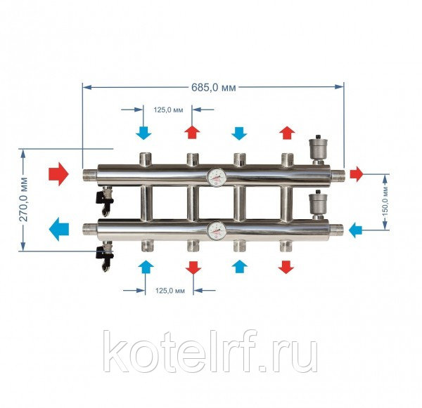
For example, a distribution pipe diameter of 90 mm is used for power not exceeding 50 kW, and if the power is twice as high, then the diameter will have to be increased to 110 mm. This is the only way to eliminate the risk of unbalancing the heating system.
The rule of 3 diameters is also useful (see the figure above). As for the calculation of the performance of the circulation pump, the specific water consumption in the heating system is taken as the basis.
Each pump is calculated separately - for the circuits and for the entire system. The figures obtained in the calculation are rounded up. A small supply of power is better than a lack of it.
Installing the collector in the heating system
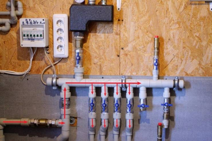
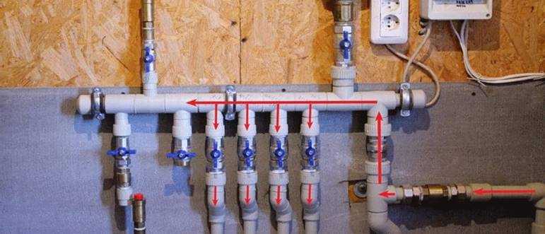
First, let's figure out how to make a collector for heating with your own hands. In addition to a large cross-section pipe, you need to prepare tees, plugs, couplings and ball valves.It is better to make a collector from polypropylene pipes than to use metal elements. Welding is used to attach fittings. Experts advise taking pipes with a reinforcing layer of fiberglass or foil.
In the process of making a comb, tees are first connected. On one side they put a plug, and on the other they fix bottom corner filing. Segments of pipes are soldered to the branches, on which stop valves and other necessary elements are installed.
Regardless of which distributor will be used (store or home-made), the installation of the heating manifold takes place after the preparation of the network elements:
- In the dressing room, corridor or pantry, a metal cabinet is installed on the wall to install the comb. You can make a regular niche at a small height from the floor.
- An expansion tank must be installed in the system, the volume of which is 10% higher than the total amount of coolant circulating in the network. It is placed on the return line in front of the pumping equipment. In the case of using a hydraulic gun, the tank is installed in front of the pump on a small circuit.
- A circulation pump is mounted on each laid outlet. It is better to install it on the return line. The shaft of the pump unit must be strictly horizontal.
The process of assembling and connecting the distribution manifold is given in the instructions for each device. Leakage is minimized by the minimum number of tees and connections.
The principle of operation of the distribution comb for heating
 In reality, it has a simple design, consisting of a small number of fixtures and components.That is why it deservedly enjoys great popularity among buyers for installation in the heating system of individual housing construction.
Basic building blocks:
- supply manifold;
- outlet collector;
- ball control valve;
- shut-off control valve;
- make-up valve of the heating system;
- coolant flow control valve;
- air vent.
The principle of operation of the installation is quite simple:
- The coolant heated in the heating boiler enters the supply manifold.
- In which it is proportionally distributed between the supply pipes connected to the house heating pipes and radiators in each heated room.
- After the hot coolant enters the heating devices, the process of heat transfer through convection and radiation from hot water to the air in the room takes place.
- The cooled coolant enters the return pipeline through which it follows to the return manifold and then again enters the boiler unit for the next heating cycle.
Setting up a comb for underfloor heating
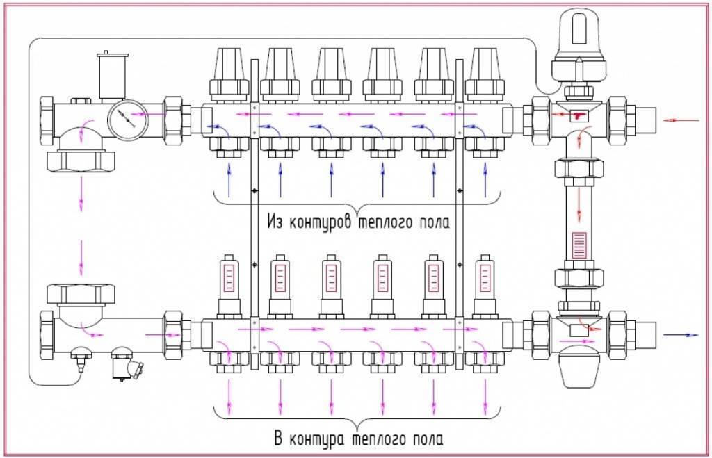
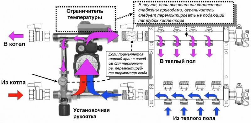
After assembly, installation and connection, the underfloor heating comb must be configured - set the required temperature level and water flow for each individual circuit. With the first parameter, everything is solved very simply - on the thermal head, located on the corresponding outlet in the "return" collector, the required temperature level is set by scrolling.
With the flow rate setting, everything is much more complicated - each circuit has its own length, and there are no general patterns for adjustment.The fastest way to do this is to make a hydraulic calculation of underfloor heating sections using software that you can get on the website of one of the comb manufacturers.

The flow meter in the manifold supply line is equipped with an indicator bulb. Under it is a nut, by unscrewing or tightening it, you can increase or decrease the value of the coolant flow on the circuit
Hydraulic calculation of the underfloor heating circuit, on the basis of which it is possible to calculate the flow rate and set it on the corresponding branch of the comb
But if for some reason you do not want to deal with flow control, then there is an easier, but time-consuming way. It lies in the fact that the setting is carried out “by feeling” - if the room is too cool, then the flow rate on the collector increases, if the floor is too hot, then, on the contrary, it decreases. But due to the general inertia of the system, such a process can be seriously delayed. In addition, it must be borne in mind that without a preliminary hydraulic calculation, it will be impossible to immediately achieve the optimal result.
However, the process of adjusting the flow rate and temperature of the warm floor is not in itself complicated - just twist the flow meter and thermometer on the supply and return manifolds in the right direction.
Design features of a warm floor without a mixing unit
Is it possible to do without a mixing unit? Experts believe that the heating system can function normally without a mixing unit, provided that the heating in the house is organized using low-temperature circuits. This is possible if the water is heated only to a certain point.


Features of laying warm water floors
Example: heating is operated by an air source heat pump. If you use the same boiler for heating the house and heating water for the shower, then you cannot do without a mixing unit.
The main disadvantage of such a heating system is the need to insulate the living space. In addition, thermal insulation works are also added. Flaws:
Water floor device
- The floor is laid in close proximity to the heating elements;
- The maximum area should not exceed 25 m²;
- It is necessary to contact a specialist who will help calculate the power of the water floor and the rate of cooling of the coolant in the water supply. If the temperature difference is too high, condensation will form. High humidity on the surface of the pipes leads to a rapid breakdown of the pipeline.
Thus, it is not necessary to install a mixing unit for a warm floor with your own hands if you plan to heat a small room up to 40 m². Design features of this assembly:
Scheme of structural elements and equipment of a water-heated floor
- A thermal relay TR is mounted on the reverse side of the manifold, which in the future will be connected to a 220 V network. This connection allows you to slightly change the direction of the coolant: the liquid begins to flow from the boiler to the supply manifold, from where it is already heated evenly distributed through the pipeline. The circulation of water through the pipes produces a pumping engine;
- Having made a full circle, the water returns to the collector. At this stage, the manifold detects the temperature of the liquid and turns off the pump motor.The movement of hot liquid gradually slows down, due to which the house is heated. The mechanism starts the pump motor again after the temperature drops, and the whole cycle repeats - first, the coolant enters the boiler, from where it is evenly distributed over the loops.
Experts believe that when a mixing unit for a warm floor was not installed with your own hands, it is better to play it safe by installing a relay. This device will completely cut down the functioning of the water floor if the temperature sensor detects too high a temperature of the pipes.
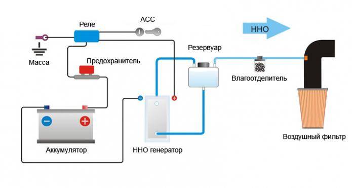
Wiring diagram for underfloor heating thermostat
Note that modern plastic tolerates high temperatures without any problems. For example, even the cheapest pipe can easily withstand 80–90 degrees
Please note that laminate and linoleum are not designed for overheating. 35-45 degrees is the maximum they can withstand.
Mixing unit for underfloor heating on three-way valves
Compalan distribution manifold
Despite the fact that there is a large assortment of distribution manifolds of different sizes in hardware stores, it is sometimes difficult to choose a device exactly for your heating system. Either the number of contours or their cross section may not match. As a result, you will have to make a monster from several collectors, which will obviously not have the best effect on the efficiency of the heating system. Yes, and such pleasure will not be cheap.
At the same time, you should not believe the stories of the "experienced" that the system can work perfectly even with a direct connection to the boiler. This is mistake.If your heating system has more than three circuits, then installing a distribution manifold is not a whim, but a necessity.
But in the absence of a distribution manifold for sale that suits your parameters, it is quite possible to do it yourself.
Heating distribution manifold device
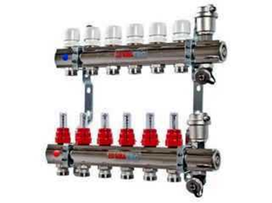
Distribution combs for heating, depending on the connected devices, can have from 2 to 20 circuits, and the design allows this number to be increased if necessary. In the production of comb elements, materials with a high degree of resistance to water impurities and external factors are used. Usually the bodies are made of stainless steel or brass.
Such elements are usually quite expensive, but their service life reaches tens of years. Simple and cheap counterparts made of polypropylene are inferior to metal products in all respects.
When choosing a manifold, it is necessary to pay attention to the maximum possible pressure, flow capacity, number of connection points and the acceptability of mounting accessories.
Each connection point can be equipped with drain valves or shut-off or control valves. With their help, it is possible to block the necessary branch during maintenance or repair without blocking the main flow of the heat-carrying fluid.


To control thermal processes in separate rooms, air outlet and drain valves, heat meters and flow meters can be mounted on the comb body.
The collector system has a fairly simple principle of operation.After the heating boiler, the heated coolant flows into the supply comb. In the inner part of the collector, it slows down the movement. This is ensured by the increased (in relation to the main) diameter of the inner part of the device. Then the coolant is evenly distributed between the individual connection branches. Entering the connection pipes, having a diameter smaller than the collector, the coolant continues to move to the devices that directly heat the room.
All elements, whether it is a floor heating grid, a radiator or a water convector, receive a coolant of equal temperature, this is achieved by setting special flow meters that control the amount of coolant supplied to each branch. For example, in order to achieve the same temperature of the warm floor in the near and far room, it is necessary to set the corresponding flow meters so that the coolant moves more slowly through the pipes in the branch of the near room, and faster in the branch of the far room.

After heat transfer, the liquid moves through the pipeline towards the return manifold, followed by direction to the heating boiler.
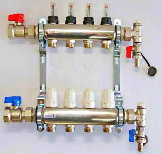
Whatever type the heating system of any house would have, it almost always contains heating radiators. The most popular and popular type of collectors are devices that distribute heat flows to radiators.
The radiator distributor assembly usually consists of two distributor combs connected to each other. The first directs the liquid to the radiators, the second returns to the boiler. Such collectors, as a rule, do not supply additional equipment and devices, in order to save money.
According to the type of connection, the collectors can be divided into devices with top, bottom, side or diagonal connection. More often than others, the lower connection method is used. In this case, it is possible to hide the contours under the decorative details of the floor, and to maximize the advantages of individual heating.
If the house has several floors, a collector assembly for radiators is installed at each level. The installation site can be a special technological recess or a shield that provides free access to the comb.
Ideally, all connection branches should have the same length. If it is impossible to maintain a single length of the circuits, then an individual pump can be installed on each of them, which maintains the circulation of the coolant. According to this scheme, warm water floors are usually equipped, each branch of which is equipped not only with its own pump, but also with automation.
Installation features and cost
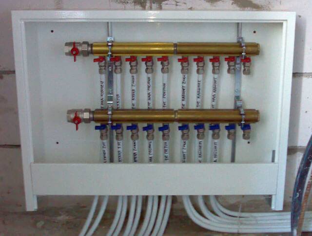
First of all, you need to choose a place to mount the collector. It is best to place this equipment in such a way that it is located at a minimum distance from adjustable heating circuits.
In height, the installation must be higher than the heating pipes. Otherwise, it will be difficult to bleed the air that may be in the pipes. To accommodate the equipment, you need to mount a special cabinet.
It can be open or closed. In the first case, it is practically a metal frame, in the second case it is a plastic or wooden cabinet. It is most convenient to equip a niche in the wall for this purpose.
An important part is the adjustment of the valves. When sold, the device is accompanied by a scheme for their adjustment, which is made in the form of a special table
Comb for underfloor heating Giacomini. To carry out this operation, you need to remove the cap from each valve (of course, this must be done before connecting the water to the collector)
Then, with a special hex wrench, tighten it completely. After that, in accordance with the table, open the valve to the desired number of revolutions.
To carry out this operation, it is necessary to remove the cap from each valve (of course, this must be done before connecting the water to the collector). Then, with a special hex wrench, tighten it completely. After that, in accordance with the table, open the valve to the desired number of revolutions.
The adjustment carried out will allow the comb to work reliably and balanced for a long time.
Here are approximate prices for various configurations:
It is recommended to buy products that belong to a well-known and reliable brand manufacturer. This allows parts to be replaced or added with 100% compatibility.


If the apartment has several heating systems for underfloor heating, then several combs may be needed.
What is a comb for?
What makes up the functionality and efficiency of the heating system? It should provide a comfortable temperature in all areas of the house and the necessary heating of water. In addition, it must be safe during operation and as maintainable as possible.

One of the functions of the comb is the ability to turn off the supply of coolant to a separate circuit of the heating system. This allows you to carry out repairs without turning off the heating as a whole.
All these conditions of normal operation help to solve the functional element of the collector (beam) heating wiring diagram, which is called a collector or comb. Suppose, in a house, suddenly, as it most often happens, a radiator or pipe joints leaked. If there is a comb, this local problem can be solved without turning off all heating. It is enough, simply by closing the desired valve, to turn off only the area that needs to be repaired.
In addition, one collector, which is installed on the entire heating system of the cottage, will perfectly cope with the function of controlling the heating process. He will be able to adjust the temperature in every room of the house. Using this device allows you to control the heating system quite efficiently and simply. At the same time, the cost of manpower and resources is reduced to a minimum.
Comb for heating, distribution manifold.
Heating distribution manifold
If this wiring is presented in the simplest version, then:
The number of outgoing pipes depends on the conditions of use and the number of radiators. Thanks to the comb, the fluid flow in the pipes is optimized. It also smooths out pressure drops in the system. The collector distributor is used in beam distribution due to the presence of separate pipes for the removal and supply of coolant for each battery. It is due to such a device that the uniform heating of the radiators and the possibility of their separate adjustment are ensured. In addition to the above advantages, the collector allows you to include additional systems in the overall system. designs. (for example: swimming pool heating).
Heating distribution manifold
Summarizing the above, we can distinguish the following positive aspects of the distribution manifold:
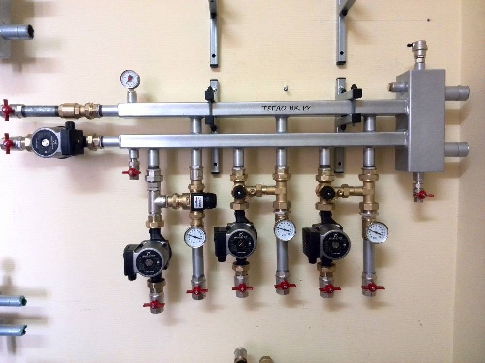
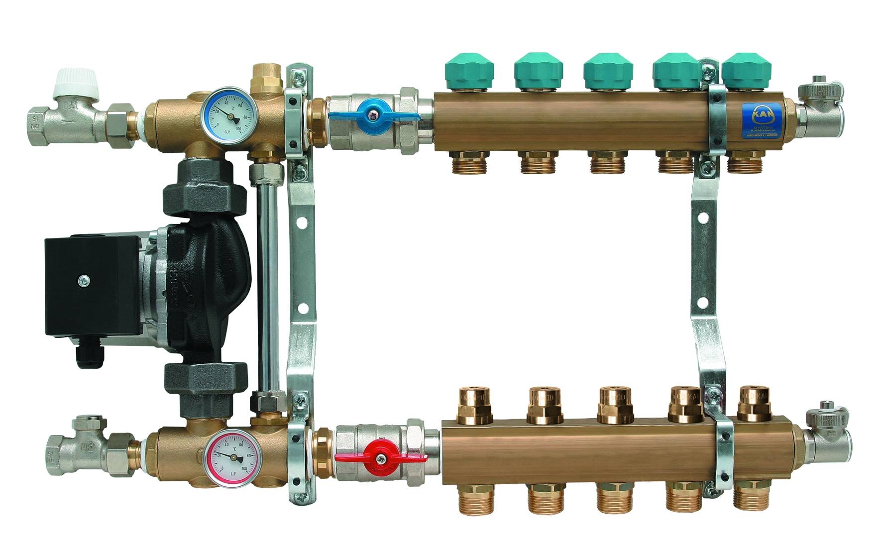
There are also two types of collectors according to the principle of operation. There are combs for boiler rooms and local ones.
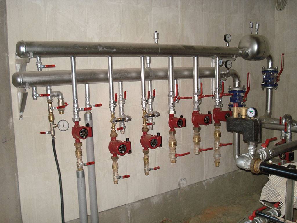
In the first type, the supply part delivers liquid to individual parts of the heating system and is therefore equipped, in addition to taps, with circulation pumps. In addition, it provides various sensors: for pressure, temperature control and hydraulic arrow.
Heating distribution manifold with circulation pump