- What are USB connectors and plugs
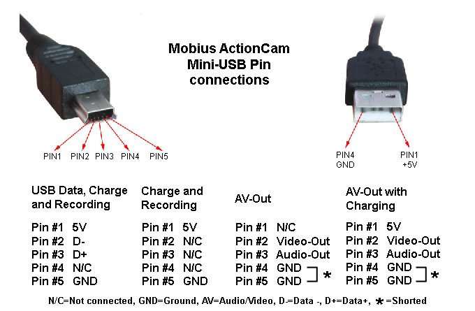
- Mini USB Pinout
- What to do if the right cable is not available
- USB power
- Purpose and types
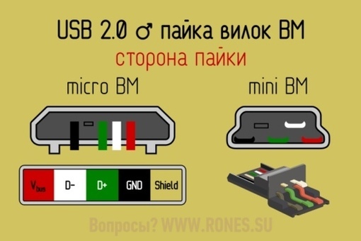
- Features of cable desoldering on connector pins
- USB 3.0 micro pinout
- USB pinout on the motherboard
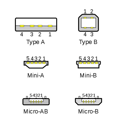
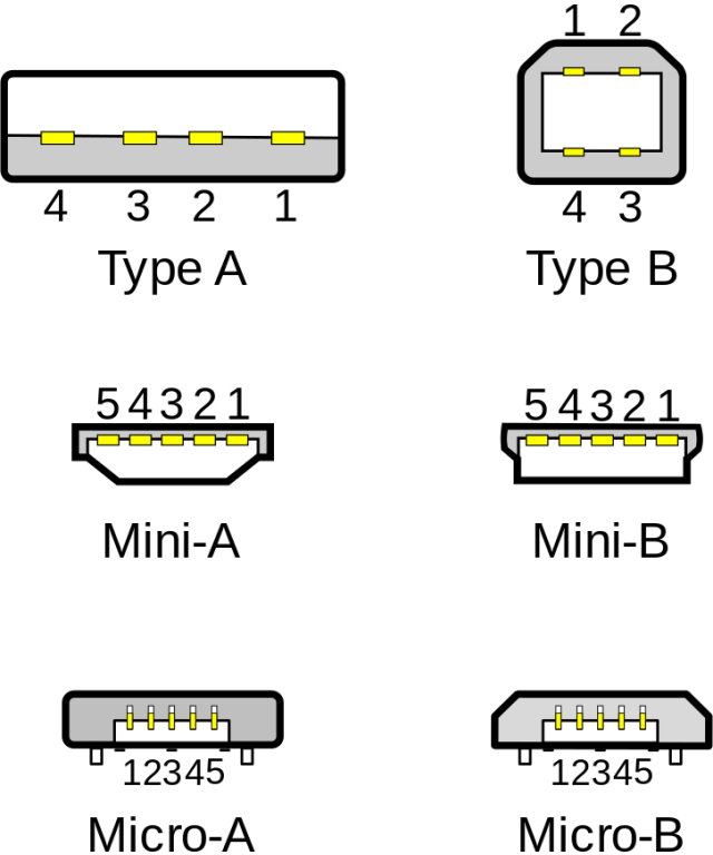
- Connector types
- How to remake the plug with your own hands
- The next level of the USB 3.2 specification
- Types of USB connectors, main differences and features
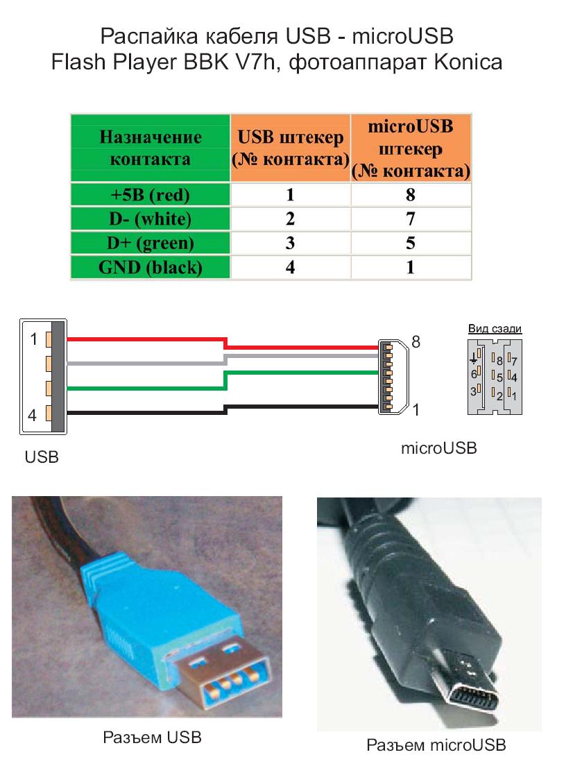
- Pinout of USB ports, pinout of micro usb, mini connector for charging
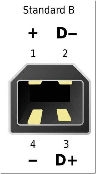
- Connector diagram for USB 2.0
- Types of USB connectors - main differences and features
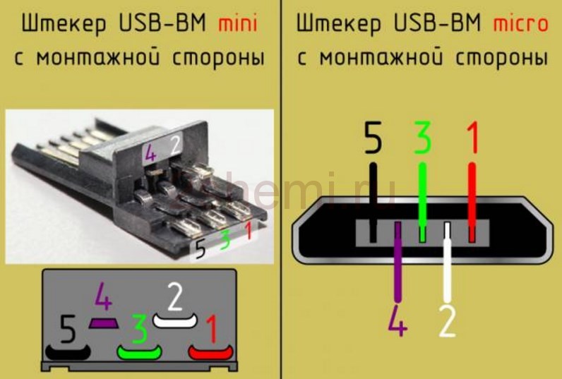
- Functions of the "legs" of the micro-USB connector
- Connector diagram for USB 2.0
What are USB connectors and plugs
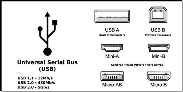
Due to the fact that there are a lot of USB connectors, confusion between them often occurs. Sometimes, after buying a cable, a wave of disappointment sets in, because it may turn out that the plug of the purchased wire does not fit the device. Therefore, in this article I will try to tell you what types of connectors USB cords have.
Despite the fact that there is a lot of information on this topic on the Internet, it usually affects development issues, gives dates of approval and commissioning, design features and pinouts.In general, more background information is provided, which is usually not of particular interest to the end user. I will try to consider connectors from a household point of view - where they are used, their advantages and disadvantages, differences and features.
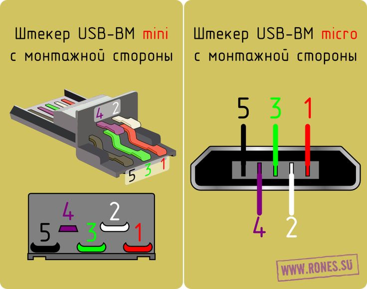
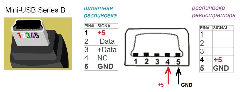
Mini USB Pinout
This connection option is used only in earlier versions of the interface, in the third generation this type is not used.
Mini USB connector pinout
As you can see, the wiring of the plug and the socket is almost identical to the micro USB, respectively, the color scheme of the wires and the pin numbers also match. Actually, the differences are only in shape and size.
Most modern peripherals are connected via the universal serial bus. Therefore, the USB pinout on the motherboard plays a very important role in the operation of a modern computer. There are two ways to install these connectors. The first is mounting directly on the board. At the same time, it is displayed on the back side and is immediately ready for work. But it is not always convenient to connect to it - and therefore they developed another way. Its essence lies in the prepared seat on the main PC board, to which the wires from the front panel are connected. And there is a plug on it.
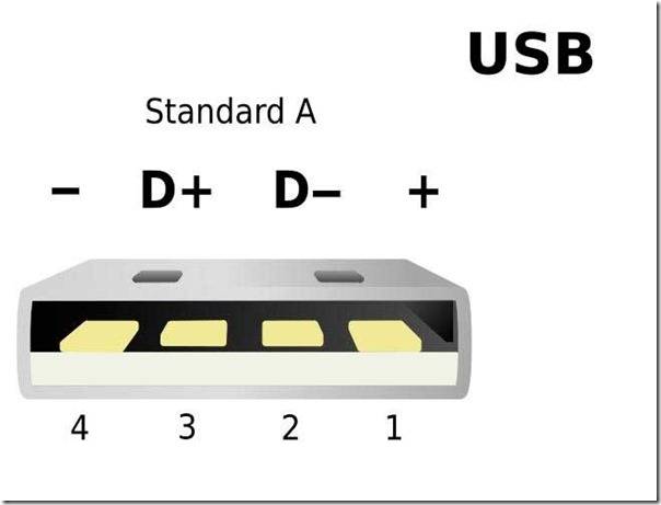
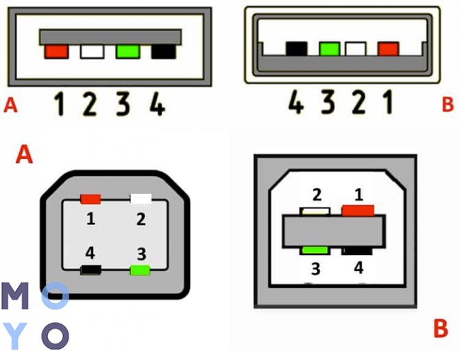
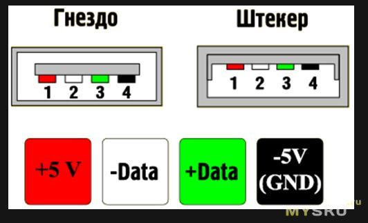
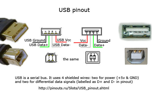
One USB 2.0 Universal Serial Port has 4 pins. The first of them is designated "+ 5V". It provides power to the peripheral device. The second and third are contacts through which information is transmitted. They are designated respectively "DATA-" (data transfer minus) and "DATA+" (data transfer plus). The last, 4th, which includes the USB pinout on the motherboard, is "GND" - ground supply.They are color-coded according to today's standards: power is red, "DATA-" is white, "DATA+" is green, and "GND" is black.
Such interface connections are made in pairs, so there are 2 USB standard connectors on the board on one contact group at once. The pinout consists of 9 pins: 4 - to one connector, 4 - to the other, and the last two play the role of the so-called key. A pin is installed in one place, and not in the other. This is done so that it is impossible to confuse them and to correctly connect. The fitting from the front panel is made in a similar way. Therefore, when connecting the first to the second should be installed without problems. If this does not happen, then you need to see if you are doing everything right.
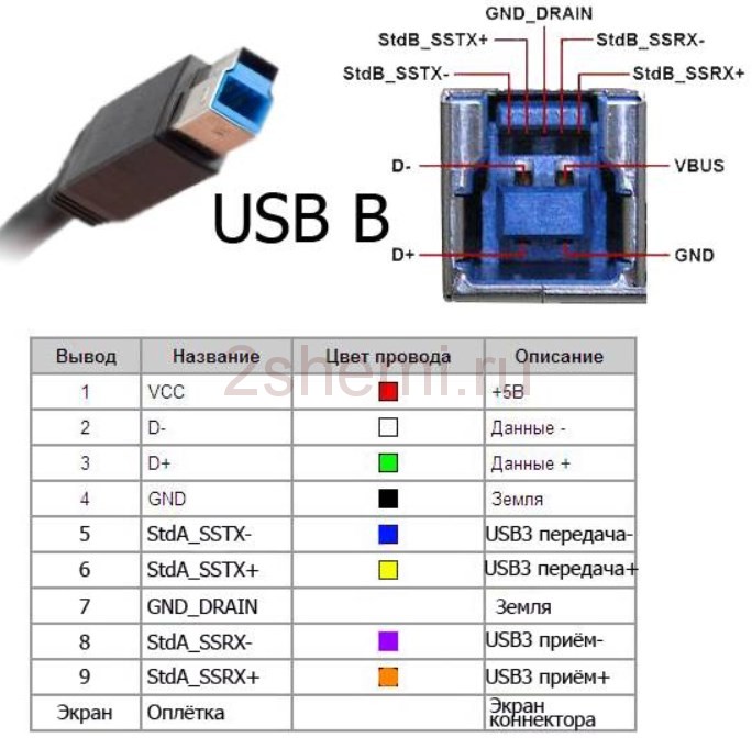
Recently, the 3rd version of the USB standard has become increasingly popular. The pinout on the motherboard is significantly different, since much more wires are used to transfer information. There are only 9 of them in this design. In addition to the previously given 4, 2 pairs of “Superspeed” + and 2 pairs of the same type, but only with a minus, are added, as well as “GND Drain” - an additional land. It is a greater number of wires that allows you to increase the data transfer rate. Their wires are respectively designated by color blue, purple - minus, yellow, orange - plus, and one more black - additional grounding. As the number of wires increases, the USB pinout on the motherboard increases in direct proportion. For such a standard, 19 contacts are already used. One of them is a key, and its purpose is to ensure that the connection is correct.
With the help of the universal serial bus, a great variety of different devices are connected to modern computers and laptops. A printer, scanner, MFP, flash drives, keyboard, mouse and other devices that greatly expand the capabilities of a PC - all this is connected to the computer through just such an interface. It is not always convenient to connect to the back of the computer, and the number of integrated connectors may not be enough. It is to solve this problem that the USB pinout on the motherboard was made, which allows you to significantly increase the number of ports.
What to do if the right cable is not available
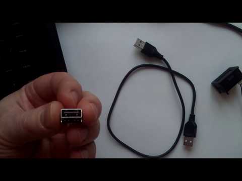
In any other case, I would just buy an adapter cable and not bother. But even on Aliexpress, where I usually buy cables and adapters, they asked too much for it. So the inner Jewish man won in me, who seeks to fix everything and do it himself, just not to pay extra rubles.
So, picking up a soldering iron ... Okay, but what if there is no soldering iron (or too lazy to bother so much) but there is an extra USB Type-C wire? We, for example, found USB C - microUSB, and, accordingly, native USB - mini USB. How to turn them into USB Type-C - mini USB (and, if desired, also get USB - mini USB)?
There is no magic - you just need to barbarically cut the wires - you can right in the middle if you want to end up with two cables. Inside you will see four wires with insulation - black, pink, green and white. There are no differences between mini and micro usb in wiring and pinouts, so nothing complicated. We remove the insulation, we tin, we wind it, we solder it at will, we wind it back and voila!
The main thing is not to forget about re-insulation - first insulate the wires individually, and then all together. For this, ordinary foil and electrical tape are quite suitable, but you can also buy heat shrink tubing to fit the cable diameter.
What was my joy when the old camera managed to charge and dump all its photo masterpieces on a laptop, while leaving a mouse and a hard drive - my inner Jewish man is not so bad, it turns out.
USB power
A voltage of 5 Volts is supplied in any USB connector, and the current cannot exceed 0.5 Amperes (for USB 3.0 - 0.9 Amperes). In practice, this means that the maximum power of the connected device can be no more than 2.5 watts (4.5 for USB 3.0). Therefore, when connecting low-power and portable devices - players, phones, flash drives and memory cards - there will be no problems. But all large-sized and massive equipment has an external power supply from the network.
And now let's move on to the types of connectors. I will not consider completely exotic options, but will only talk about the most popular and frequently used plugs. In brackets will be indicated belonging to a specific version of USB.
Purpose and types
The USB connector has a good set of features. With it, you can not only transfer large amounts of information at high speed, but also provide the device with power. The new interface quickly replaced old ports on computers, such as PS / 2. Now all peripherals are connected to the PC using USB ports.
To date, 3 versions of the USB connector have been created:
- Standard 1.1 - could not compete with faster interfaces.Using YUSB 1.1, it was possible to transfer information at a speed of no more than 12 Mbps. At that time, Apple already had an interface with a bandwidth of up to 400 Mbps.
- Version 2.0 - it is to her that the connector owes its popularity. Speeds up to 500 Mbit / s pleased not only users, but also manufacturers of electronic gadgets.
- Standard 3.0 - the maximum information exchange rate was 5 Gb / s. Although the USB connector design of this version has increased the number of pins from 4 to 9, the shape of the connector has not changed, and it is compatible with previous standards.
Features of cable desoldering on connector pins
Some special technological nuances of soldering cable conductors on the contact pads of the connectors are not noted. The main thing in such a process is to ensure that the color of the cable conductors, previously protected from insulation, matches a specific contact (pin).
Color coding of conductors inside the cable assembly used for USB interfaces. Shown from top to bottom, respectively, are the cable conductor colors for specifications 2.0, 3.0 and 3.1.
Also, if modifications of obsolete versions are desoldered, the configuration of the connectors, the so-called “father” and “mother”, should be taken into account.
The conductor soldered on the “male” contact must match the soldering on the “mother” contact. Take, for example, the option of desoldering a cable using USB 2.0 pins.


The four working conductors used in this variant are usually marked with four different colors:
- red;
- white;
- green;
- black.
Accordingly, each conductor is soldered to a contact pad marked with a connector specification of a similar color.This approach greatly facilitates the work of an electronics engineer, eliminates possible errors in the desoldering process.
A similar soldering technique is applied to connectors of other series. The only difference in such cases is the greater number of conductors that have to be soldered. To simplify your work, it is convenient to use a special tool - a reliable soldering iron for soldering wires at home and a stripper for stripping insulation from the ends of the wires.
Regardless of the connector configuration, shield conductor soldering is always used. This conductor is soldered to the corresponding pin on the connector, Shield is a protective screen.
There are frequent cases of ignoring the protective screen, when "specialists" do not see the point in this conductor. However, the lack of a shield drastically reduces the performance of the USB cable.
Therefore, it is not surprising when, with a significant cable length without a screen, the user gets problems in the form of interference.
Desoldering the connector with two conductors for organizing a power line for the donor device. In practice, different wiring options are used, based on technical needs.
Soldering the USB cable is allowed in different ways, depending on the configuration of the port lines on a particular device.
For example, in order to connect one device to another in order to obtain only a supply voltage (5V), it is enough to solder only two lines on the corresponding pins (contacts).
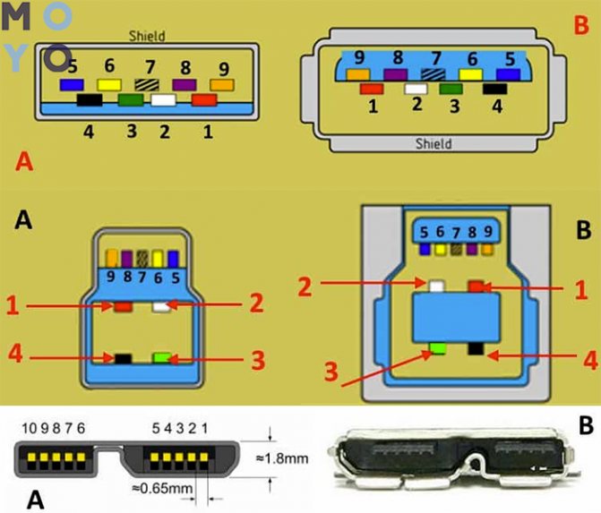
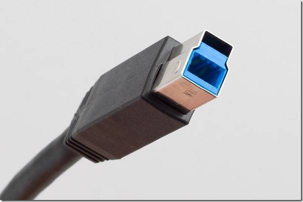
USB 3.0 micro pinout
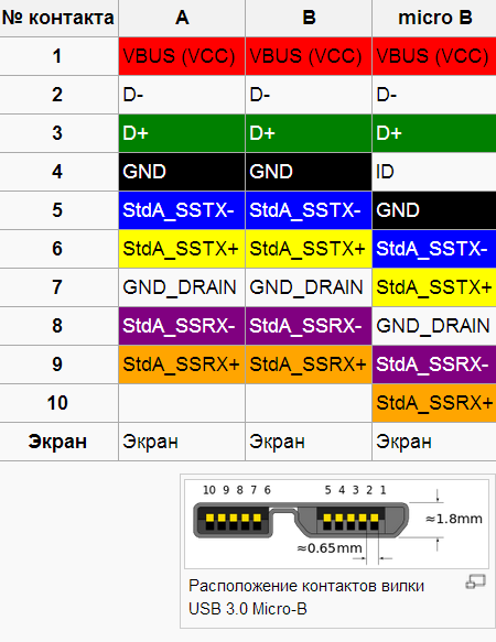
The pinout (pinout) of USB 3.0-micro does not differ in the number of pins (with the exception of one) or their purpose and color from the basic USB 3.0 connector. However, this is a rather peculiar connector that requires special attention.
Looking at the figure below, you can immediately notice that it is made somewhat unusual than its "big brother" micro-USB 2.0.
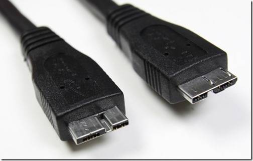
These are far from all the differences. There are two types of micro-USB 3.0 connectors (plugs). They differ both visually and in their pinout (albeit slightly)
The name of these connectors is USB 3.0 Micro A and USB 3.0 Micro B. The sockets (sockets) of these connectors are also different. There is also a universal USB 3.0 Micro AB socket. USB 3.0-micro pinout material deserves a separate topic. Therefore, it was decided to consider the topic of micro-USB 3.0 wiring in more detail in the article Micro-USB 3.0 pinout. Finally, consider another type of USB 3.0 connector.
They differ both visually and in their pinout (albeit slightly). The name of these connectors is USB 3.0 Micro A and USB 3.0 Micro B. The sockets (sockets) of these connectors are also different. There is also a universal USB 3.0 Micro AB socket. USB 3.0-micro pinout material deserves a separate topic. Therefore, it was decided to consider the topic of micro-USB 3.0 wiring in more detail in the article Micro-USB 3.0 pinout. Finally, consider another type of USB 3.0 connector.
USB pinout on the motherboard
By default, motherboards already have output USB ports on the rear panel. But in addition, there are almost always pin outputs, for example, for the front panel of the system unit. There is nothing complicated in connecting. There are two switching options. This can be a set of chips to be inserted into the pins, or a whole block is used. One set of pins on the board is designed for two USB connectors. For version 2.0, 9 contacts are used, for version 3.0 - 19.If the connection is made using a set of chips, then only four pins can be used for one connector, and in the case of 3.0 - 9.
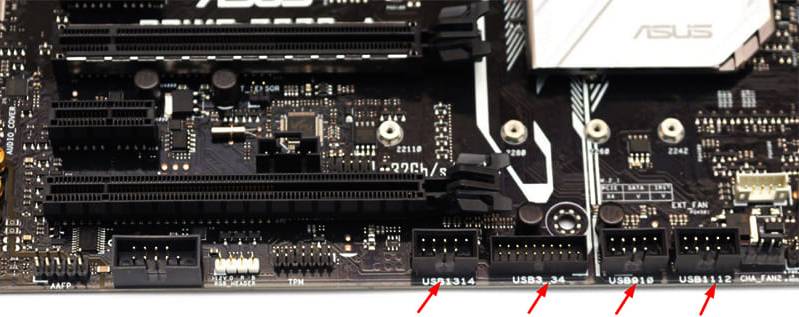 The USB connectors on the board are signed. USB 3.0 is noticeably different from 2.0 in size
The assignment of pins on the motherboard is strictly regulated. Both lines have the same set, with the exception of the fifth contact, which serves as a kind of beacon so as not to connect the unit incorrectly. If it is on the right, then the leftmost pair of contacts is responsible for transmitting power, then two pairs for data and the right one is ground. You can navigate both by the inscriptions on the chips and by the colors. Although the latter method is not so reliable.
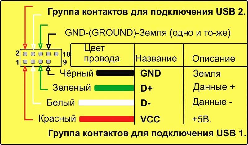 USB 2.0 pinout on motherboard
It makes no sense to study the pin assignment for USB 3.0 on the board, since the developers have simplified the connection as much as possible. For this, a chip is used with all the necessary set of contacts, which is almost impossible to plug incorrectly.
In general, the USB pinout is gradually becoming a thing of the past. It was relevant to know the placement of contacts for versions 1.0 and 2.0. Then, cables and connectors began to be more and more unified and designed with the least problems for users when connecting. Most of them will never have to deal with manual installation or soldering of contacts at all. This is, rather, the lot of radio amateurs and "geeks".
 Watch this video on YouTube
Previous DIY HomiusHow to protect the front door from breaking: 5 easy ways
Next DIY HomiusDo-it-yourself mobile home: how to turn a minibus into a cozy home
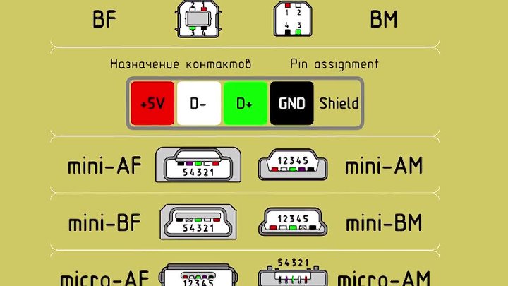
Connector types
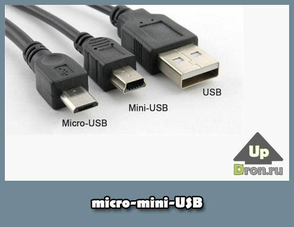
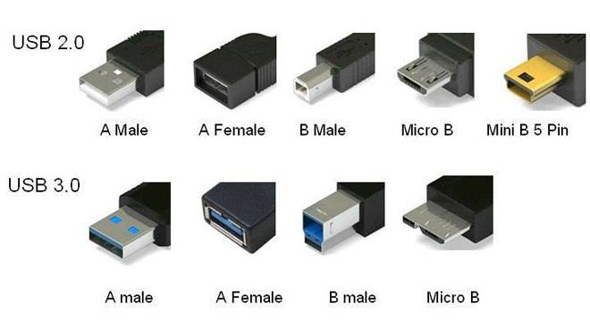
The second and third versions of the connectors are distinguished by size: Mini USB (small sizes), Micro USB (even smaller sizes); as well as types: A, B.
USB connector 2.0 type A.
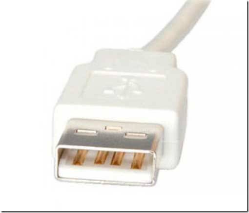
A reliable connector whose main characteristic is the ability to withstand more than one connection, while not losing its integrity.
The cross section of the connector has a rectangular shape, which creates additional protection when connected.
Its disadvantage is its large size, and all modern devices are portable, which influenced the development and production of connectors of a similar type, but smaller.
USB 2.0 type A was introduced in the nineties and is still the most used today.

It has a significant part of low-power devices: keyboard, mouse, flash drive and others.
USB connector version 2.0 type B.
Basically, we find its application in stationary devices with large dimensions. These include scanners, printers, less often ADSL modems.
Rarely, but still it happens that cables of this type are sold separately from the equipment itself, because they are not included in the set of the technical device. Therefore, check the complete set of devices.
Connectors of this type are not as popular as type A connectors.
The square and trapezoidal shape is inherent in all type B connectors.
These include both Mini and Micro.
The peculiarity of the section of connectors of type "B" is their square shape, which distinguishes it from other types.
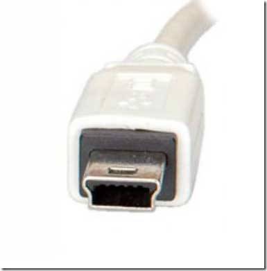
Mini USB connectors of the second version of type B.
The name of this type of connector indicates that it has a very small size.And this is not surprising, because the modern market is increasingly offering miniature goods.
Through the use of personal hard drives, card readers, players and other small devices, Type B USB Mini connectors have become very popular.
It should be noted the unreliability of such connectors. With frequent use, it loosens.
But the use of models of USB Mini type A connectors is extremely limited.
Micro USB 2.0 type B connectors.
Micro USB connector models are more advanced than Mini USB models.
This type of connector is incredibly small.
Unlike the previous mini types presented, these connectors are very reliable with their fastenings and fixing the connection.
The Micro USB 2.0 type "B" connector has been recognized for its qualities as the only one for general use for charging all portable devices.
What will happen over time, when all manufacturers will produce equipment adapted specifically to such connectors. Probably not long enough to see it.
But such a decision was already made in 2011 by all modern manufacturers, although the Micro USB 2.0 type “B” connector is not yet present on all devices.
Type A third version USB connectors.
USB 3.0 connectors have a high speed for transferring information due to additional contacts.


With such changes, feedback compatibility is still preserved. Its use has been established in computers and laptops of the latest generation.
USB connectors of the third version of type B.
The third version of USB type "B" connectors are not suitable for connecting USB connectors of the second version.
It is used in the operation of peripheral devices with medium and large performance.
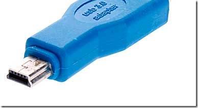
Micro USB 3.0.
Modern external drives with high speed, as well as drives such as SSD, basically, all are equipped with such a connector, which is characterized by a high speed of information exchange.
Increasingly, it occupies a leading position due to the fact that it has very high-quality connections.
The connector is easy to use due to its compactness. Its predecessor is considered to be a Micro USB connector.
Connector pinout USB.
How to remake the plug with your own hands
Now you have a pinout diagram for all popular smartphones and tablets, so if you have the skill of working with a soldering iron, there will be no problems with converting any standard USB connector to the type you need for your device. Any standard charging, which is based on the use of USB, involves the use of only two wires - this is + 5V and a common (negative) contact.
Just take any charging-adapter 220V / 5V, cut off the USB connector from it. The cut end is completely freed from the screen, while the remaining four wires are stripped and tinned. Now we take a cable with a USB connector of the desired type, after which we also cut off the excess from it and carry out the same procedure. Now it remains just to solder the wires together according to the diagram, after which the connection is isolated each separately. The resulting case is wrapped on top with electrical tape or tape. You can pour hot glue - also a normal option.
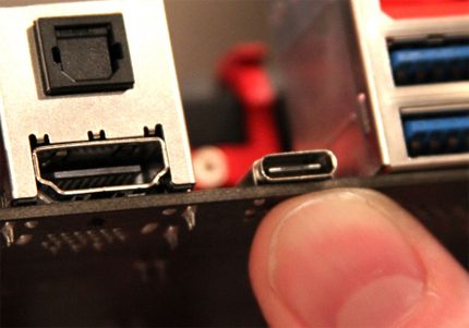
The next level of the USB 3.2 specification
Meanwhile, the process of improving the universal serial bus is actively continuing. At the non-commercial level, the next specification level, 3.2, has already been developed.
USB 3.2 type interfaces are said to promise double the performance of the previous design.
The developers managed to achieve such parameters by introducing multiband channels through which transmission is carried out at speeds of 5 and 10 Gbps, respectively.
Similar to "Thunderbolt", USB 3.2 uses multiple lanes to achieve total bandwidth, rather than trying to sync and run the same channel twice
By the way, it should be noted that the compatibility of the future interface with the existing USB-C is fully supported, since the Type-C connector (as already noted) is endowed with spare contacts (pins) that provide multi-band signal transmission.
Types of USB connectors, main differences and features
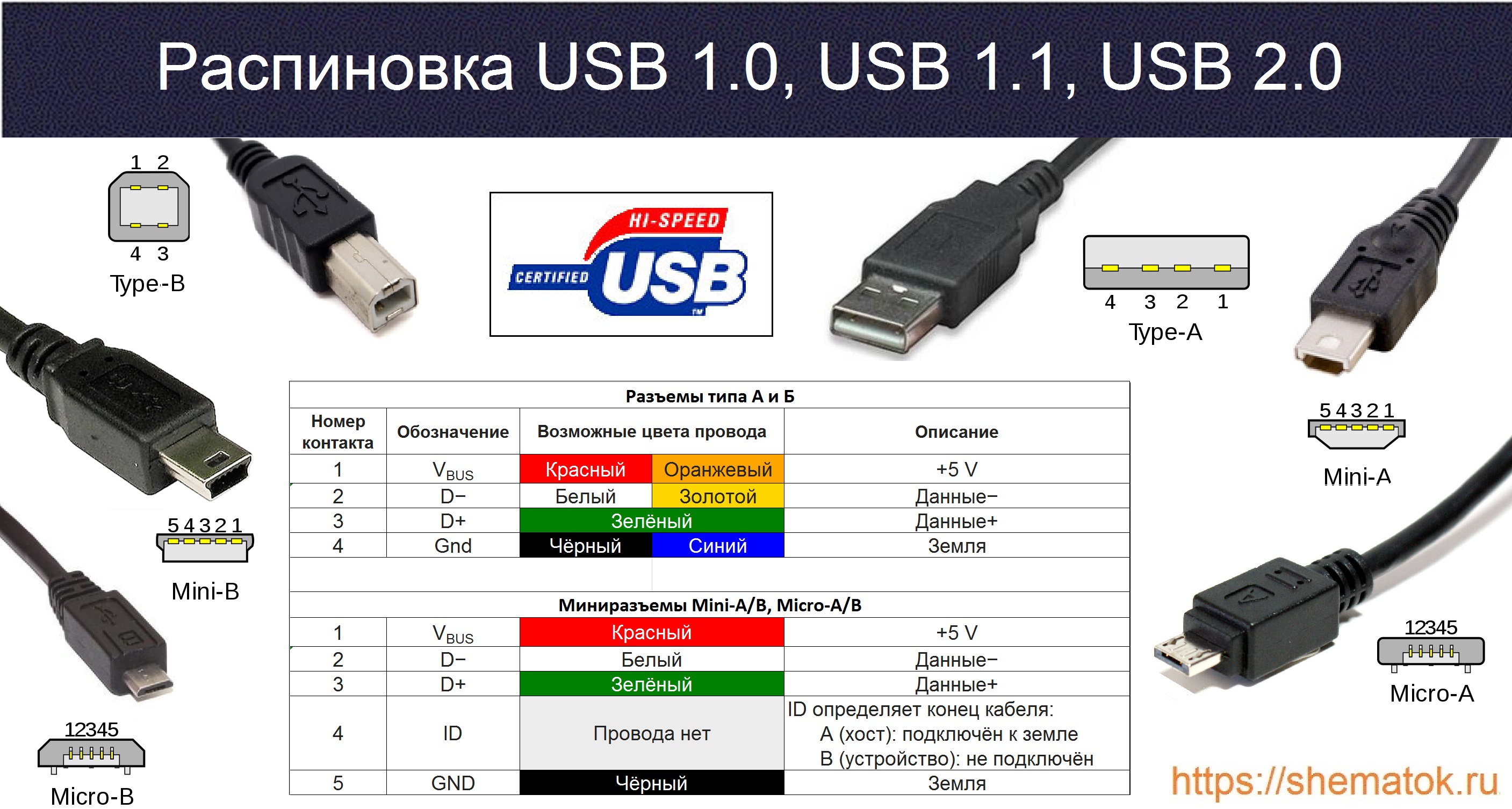
The Universal Serial Bus comes in 3 versions - USB 1.1, USB 2.0 and USB 3.0. The first two specifications are fully compatible with each other, the 3.0 tire has a partial overlap.
USB 1.1 is the first version of the device used for data transfer. The specification is used only for compatibility, since 2 operating modes for data transfer (Low-speed and Full-speed) have a low information exchange rate. Low-speed mode with a data transfer rate of 10-1500 Kbps is used for joysticks, mice, keyboards. Full-speed is used in audio and video devices.
USB 2.0 added a third mode of operation - High-speed for connecting storage devices and video devices of a higher organization. The connector is marked with HI-SPEED on the logo. The information exchange rate in this mode is 480 Mbps, which is equal to the copy speed of 48 Mbps.


In practice, due to the design and implementation of the protocol, the throughput of the second version turned out to be less than the declared one and is 30-35 MB / s. The cables and connectors of the Universal Bus Specifications 1.1 and Generation 2 have an identical configuration.
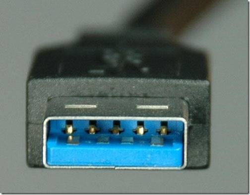
The third-generation universal bus supports 5 Gb/s, which is equivalent to a copy speed of 500 MB/s. It is available in blue, making it easy to identify which plugs and sockets belong to the upgraded model. Bus 3.0 current increased from 500mA to 900mA. This feature allows you not to use separate power supplies for peripheral devices, but to use the 3.0 bus to power them.
Specifications 2.0 and 3.0 are partially compatible.
Pinout of USB ports, pinout of micro usb, mini connector for charging
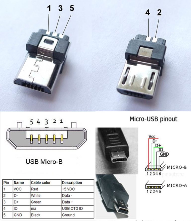
Nowadays, all mobile devices and desktop electrical appliances have data ports in their arsenal. Modern gadgets can not only exchange information via USB or micro-USB, but also charge batteries. In order to carry out a competent pinout of the contacts, first you need to study the diagrams and colors of the wiring.
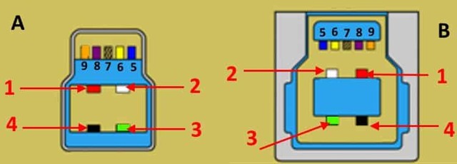
Connector diagram for USB 2.0
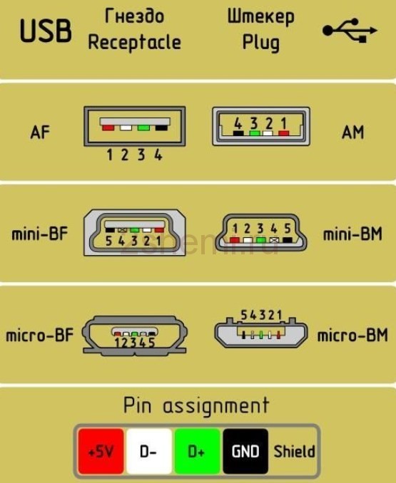
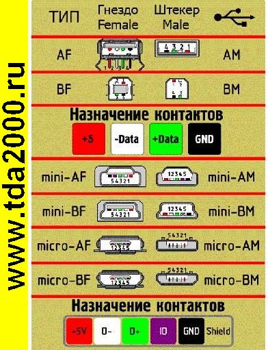
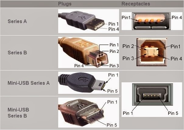
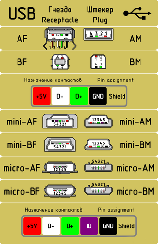
On the diagram you can see several connectors that differ from each other in a certain way. For example, an active (power) device is denoted by the letter A, and a passive (pluggable) device is denoted by the letter B. Active devices include computers and hosts, and passive devices are printers, scanners, and other devices. It is also customary to separate connectors by gender: M (male) or “male” is a plug, and F (female) or “mother” is a connector socket.There are formats in size: mini, micro and without marking. For example, if you meet the designation "USB micro-VM", then this means that the plug is designed to connect to a passive device using the micro format.
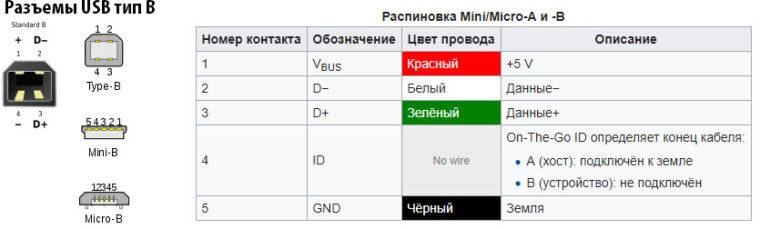
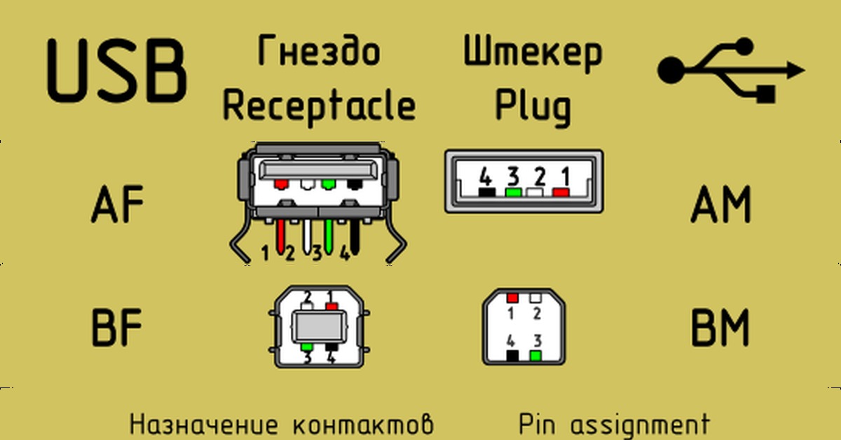
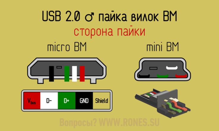
To pin out sockets and plugs, you will need knowledge about the purpose of the wires in the USB cable:
- the red VBUS ("plus") carries a constant voltage of 5 volts relative to GND. The minimum value of the electric current for it is 500 mA;
- the white wire is connected to the "minus" (D-);
- the green wire is attached to the "plus" (D +);
- The black color of the wire means that the voltage in it is 0 Volts, it carries a negative charge and is used for grounding.
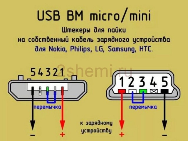
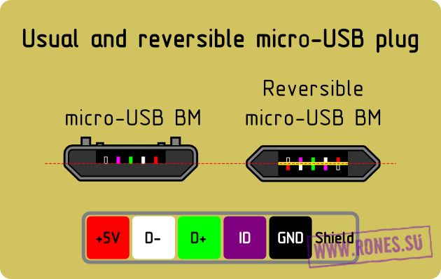
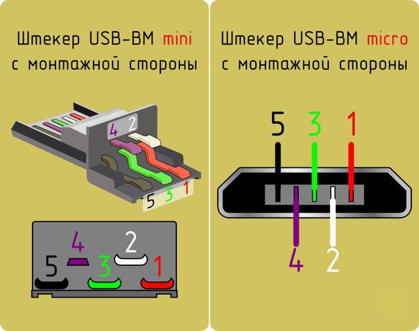
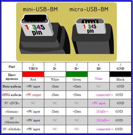
In mini and micro formats, the connectors contain five pins each: red, black, white and green wires, as well as ID (which is closed to GND in type A connectors, and not used at all in connectors B).
Sometimes you can also find a bare Shield wire in the USB cable. This wire is not numbered.
If you use a table in your work, then the connector in it is shown from the outer (working) side. The insulating parts of the connector are light gray, the metal parts are dark gray, and the cavities are marked in white.
In order to carry out the correct USB desoldering, you need to mirror the image of the front of the connector.
Connectors for mini and micro formats on USB consist of five pins. Therefore, the fourth contact in the type B connectors will not have to be used in operation. This contact in type A connectors closes with GND, and for GND itself, the fifth one is used.
As a result of not tricky manipulations, you can independently make a pinout for USB ports of various formats.
Usb wiring version 3.0 is distinguished by the addition of four colored wires and an additional ground. Due to this, the USB 3.0 cable is noticeably thicker than its younger brother.
Schemes for connecting USB devices to each other and wiring device plugs:
- PS/2 To USB port
- Joystick Defender Game Racer Turbo USB-AM
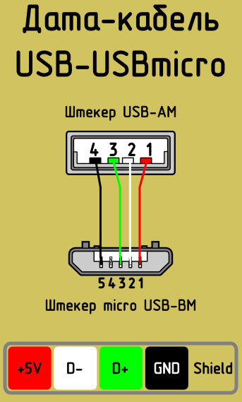
- Unsoldering usb am and micro usb bm, for charging and transferring data to a computer
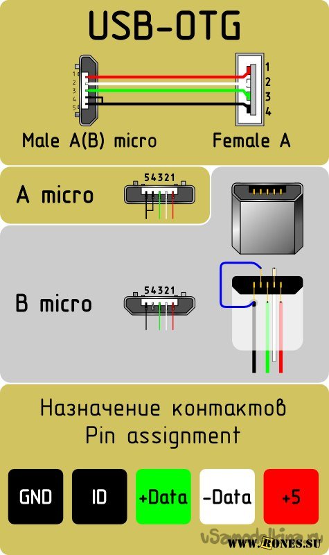
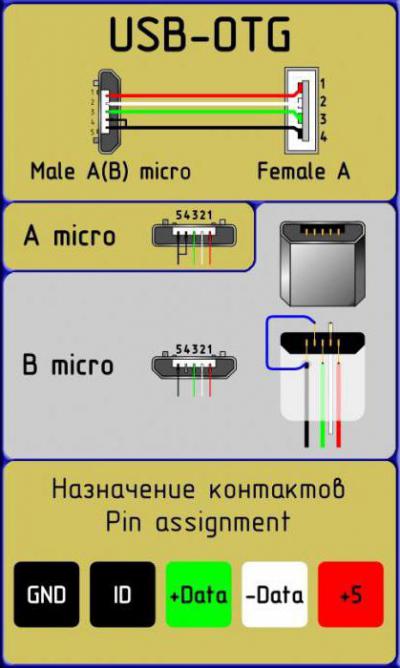
- USB-OTG
- USB pinout SAMSUNG GALAXY TAB 2
Types of USB connectors - main differences and features
There are three specifications (versions) of this type of connection partially compatible with each other:
- The very first variant that has become widespread is v 1. It is an improved modification of the previous version (1.0), which practically did not leave the prototype phase due to serious errors in the data transfer protocol. This specification has the following characteristics:
- Dual-mode data transmission at high and low speed (12.0 and 1.50 Mbps, respectively).
- Ability to connect more than a hundred different devices (including hubs).
- The maximum cord length is 3.0 and 5.0 m for high and low baud rates, respectively.
- The nominal bus voltage is 5.0 V, the permissible load current of the connected equipment is 0.5 A.
Today, this standard is practically not used due to low bandwidth.
- The second specification that dominates today. This standard is fully compatible with the previous modification. A distinctive feature is the presence of a high-speed data exchange protocol (up to 480.0 Mbps).
A clear demonstration of the advantages of USB 2.0 over other interfaces (transfer rate of 60 MB per second, which corresponds to 480 Mbps)
Due to full hardware compatibility with the younger version, peripheral devices of this standard can be connected to the previous version. True, in this case, the throughput will decrease up to 35-40 times, and in some cases even more.
Since there is full compatibility between these versions, their cables and connectors are identical.
Let's pay attention that, despite the bandwidth specified in the specification, the real data exchange rate in the second generation is somewhat lower (about 30-35 MB per second). This is due to the peculiarity of the protocol implementation, which leads to delays between data packets.
Since the read speed of modern drives is four times higher than the bandwidth of the second modification, that is, it did not meet the current requirements.
- The 3rd generation universal bus has been designed specifically to address bandwidth constraints. According to the specification, this modification is capable of exchanging information at a speed of 5.0 Gbps, which is almost three times the reading speed of modern drives. Plugs and sockets of the latest modification are usually marked in blue to facilitate identification of belonging to this specification.
USB 3.0 connectors have a distinctive blue color
Another feature of the third generation is an increase in the rated current up to 0.9 A, which allows you to power a number of devices and abandon separate power supplies for them.
As for compatibility with the previous version, it is partially implemented, it will be described in detail below.
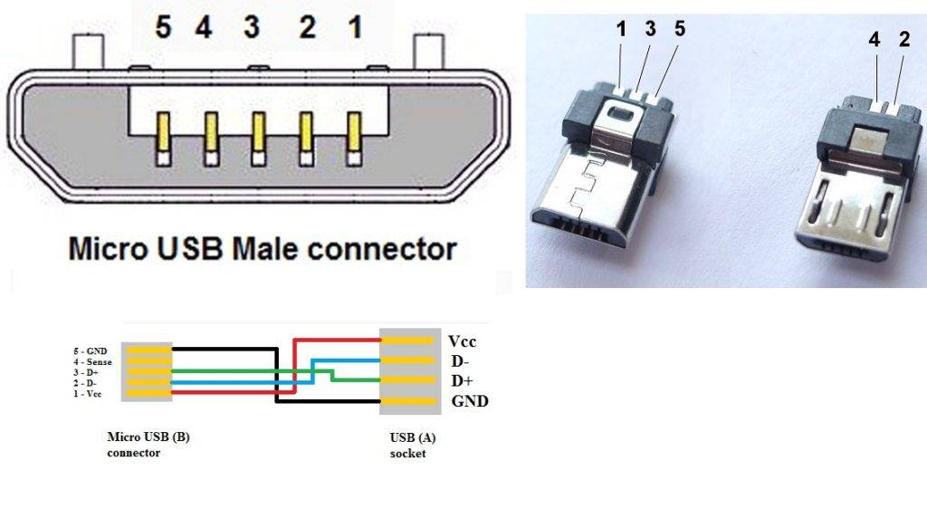
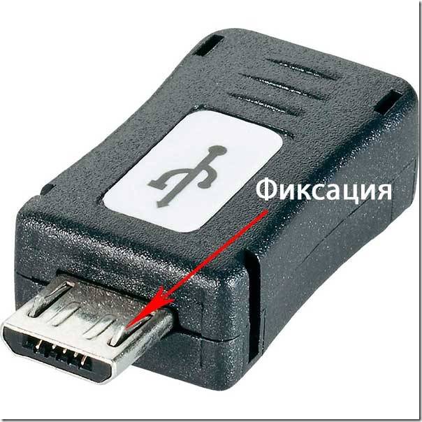
Functions of the "legs" of the micro-USB connector
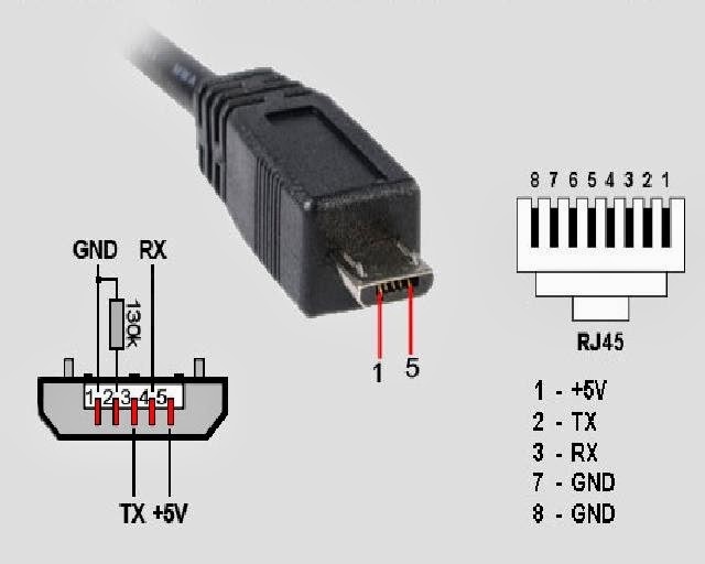
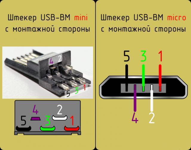
The micro-USB connector is used to charge small and portable volatile devices and synchronize data between PC and gadgets. It consists of five "legs". Two "legs" are separated on different sides of the case: one is a positive value of 5V, the second is negative. This arrangement reduces the chance of breakage.


Close to the negative "leg" there is another contact, which easily breaks if it is carelessly connected to the port. If this "leg" is damaged, the cable fails.
The battery icon may show connection progress, but actual charging is not possible. Most often, this damage leads to the fact that the gadget does not respond to connecting the plug.
The two remaining "legs" are used for data exchange and synchronization between devices. With the help of them, it is possible to upload and download files from the gadget to the PC and back, transfer video and photos, audio. Work is carried out synchronously. If only one contact is damaged, the work of the second one stops. Knowing the pinout by color allows you to solder the wires correctly and resume the plug.
Connector diagram for USB 2.0
On the diagram you can see several connectors that differ from each other in a certain way. For example, an active (power) device is denoted by the letter A, and a passive (pluggable) device is denoted by the letter B. Active devices include computers and hosts, and passive devices are printers, scanners, and other devices. It is also customary to separate connectors by gender: M (male) or “male” is a plug, and F (female) or “mother” is a connector socket. There are formats in size: mini, micro and without marking.For example, if you meet the designation "USB micro-VM", then this means that the plug is designed to connect to a passive device using the micro format.
To pin out sockets and plugs, you will need knowledge about the purpose of the wires in the USB cable:
- the red VBUS ("plus") carries a constant voltage of 5 volts relative to GND. The minimum value of the electric current for it is 500 mA;
- the white wire is connected to the "minus" (D-);
- the green wire is attached to the "plus" (D +);
- The black color of the wire means that the voltage in it is 0 Volts, it carries a negative charge and is used for grounding.
In mini and micro formats, the connectors contain five pins each: red, black, white and green wires, as well as ID (which is closed to GND in type A connectors, and not used at all in connectors B).
Sometimes you can also find a bare Shield wire in the USB cable. This wire is not numbered.
If you use a table in your work, then the connector in it is shown from the outer (working) side. The insulating parts of the connector are light gray, the metal parts are dark gray, and the cavities are marked in white.
In order to carry out the correct USB desoldering, you need to mirror the image of the front of the connector.
Connectors for mini and micro formats on USB consist of five pins. Therefore, the fourth contact in the type B connectors will not have to be used in work. This contact in type A connectors closes with GND, and for GND itself, the fifth one is used.
As a result of not tricky manipulations, you can independently make a pinout for USB ports of various formats.
Usb wiring version 3.0 is distinguished by the addition of four colored wires and an additional ground. Due to this, the USB 3.0 cable is noticeably thicker than its younger brother.
Schemes for connecting USB devices to each other and wiring device plugs:


