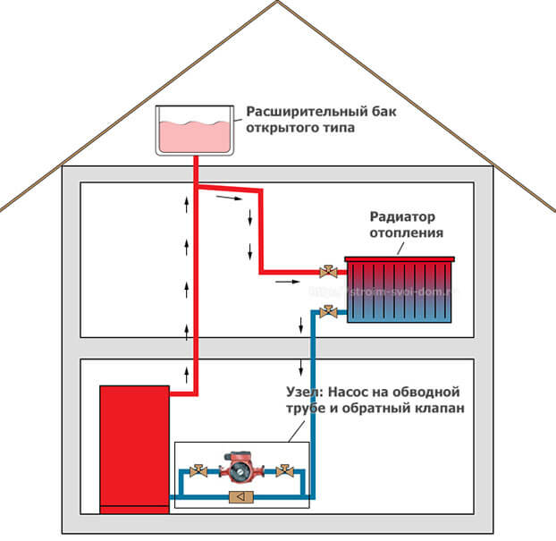
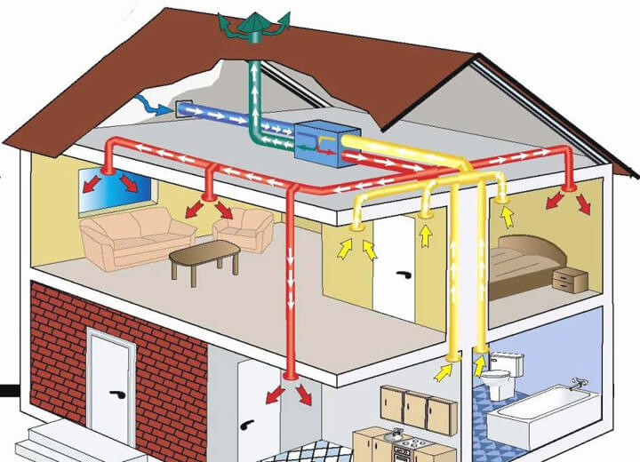
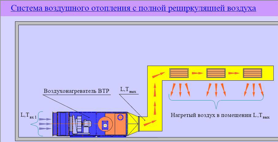
- Heat consumption for ventilation
- The cold period of the year - HP.
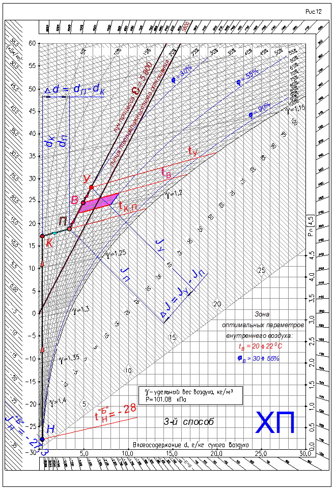
- The third method is the simplest - humidification of the outdoor supply air in a steam humidifier (see Figure 12).
- Accurate heat load calculations
- Calculation for walls and windows
- Ventilation calculation
- Calculation of heat loss in the house
- CALCULATION OF ELECTRIC HEATING INSTALLATION
- 1.1 Thermal calculation of heating elements
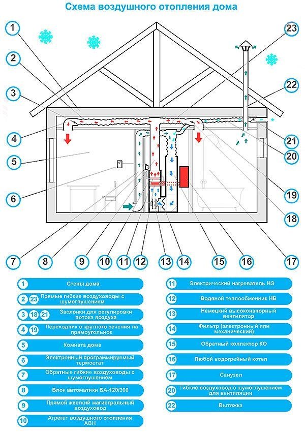
- What types are
- Features of the Antares system
- Volcano or Volcano
- The sequence of actions when installing air heating
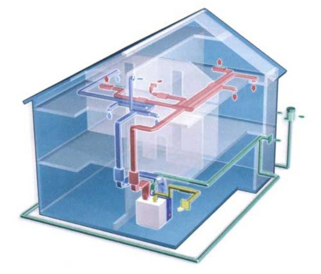
- Air heating system design
- Installation of air heating system
- Application of thermal air curtains
Heat consumption for ventilation
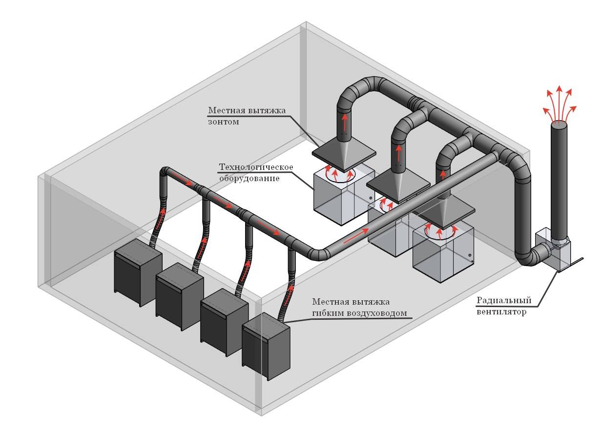
According to its purpose, ventilation is divided into general, local supply and local exhaust.
General ventilation of industrial premises is carried out with the supply of supply air, which absorbs harmful emissions in the working area, acquiring its temperature and humidity, and is removed using an exhaust system.
Local supply ventilation is used directly at workplaces or in small rooms.
Local exhaust ventilation (local suction) should be provided when designing process equipment to prevent air pollution in the working area.
In addition to ventilation in industrial premises, air conditioning is used, the purpose of which is to maintain a constant temperature and humidity (in accordance with sanitary and hygienic and technological requirements), regardless of changes in external atmospheric conditions.
Ventilation and air conditioning systems are characterized by a number of general indicators (Table 22).
The heat consumption for ventilation, to a much greater extent than the heat consumption for heating, depends on the type of technological process and the intensity of production and is determined in accordance with the current building codes and regulations and sanitary standards.
The hourly heat consumption for ventilation QI (MJ / h) is determined either by the specific ventilation thermal characteristics of buildings (for auxiliary premises), or by
At light industry enterprises, various types of ventilation devices are used, including general exchange devices, for local exhausts, air conditioning systems, etc.
The specific ventilation thermal characteristic depends on the purpose of the premises and is 0.42 - 0.84 • 10~3 MJ / (m3 • h • K).
According to the performance of supply ventilation, the hourly heat consumption for ventilation is determined by the formula
the duration of the existing supply ventilation units (for industrial premises).
According to the specific characteristics, the hourly heat consumption is determined as follows:
In the event that the ventilation unit is designed to compensate for air losses during local exhausts, when determining QI, it is not the outside air temperature for calculating ventilation tHv that is taken into account, but the outside air temperature for calculating heating /n.
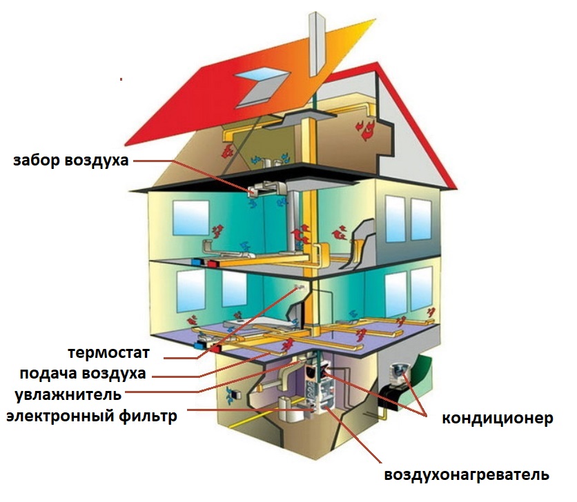
In air conditioning systems, the heat consumption is calculated depending on the air supply scheme.
So, annual heat consumption in once-through air conditioners operating with the use of outside air, is determined by the formula
If the air conditioner operates with air recirculation, then in the formula by definition Q £ con instead of the supply temperature
The annual heat consumption for ventilation QI (MJ / year) is calculated by the equation
The cold period of the year - HP.
1. When air conditioning in the cold season - HP, the optimal parameters of indoor air in the working area of the room are initially taken:
tAT = 20 ÷ 22ºC; φAT = 30 ÷ 55%.
2. Initially, we put points on the J-d diagram according to two known parameters of moist air (see Figure 8):
- outside air (•) N tH = - 28ºC; JH = - 27.3 kJ/kg;
- indoor air (•) V tAT = 22ºC; φAT = 30% with minimum relative humidity;
- indoor air (•) B1 tIN 1 = 22ºC; φIN 1 = 55% with maximum relative humidity.
In the presence of heat excesses in the room, it is advisable to take the upper temperature parameter of the indoor air in the room from the zone of optimal parameters.
3. We draw up the heat balance of the room for the cold season - HP:
by sensible heat ∑QХПЯ
by total heat ∑QHPP
4. Calculate the flow of moisture into the room
∑W
5. Determine the thermal tension of the room according to the formula:
where: V is the volume of the room, m3.
6. Based on the magnitude of the thermal stress, we find the gradient of temperature rise along the height of the room.
The air temperature gradient along the height of the premises of public and civil buildings.
| Thermal tension of the room QI/Vpom. | gradt, °C | |
|---|---|---|
| kJ/m3 | W/m3 | |
| Over 80 | Over 23 | 0,8 ÷ 1,5 |
| 40 ÷ 80 | 10 ÷ 23 | 0,3 ÷ 1,2 |
| Less than 40 | Less than 10 | 0 ÷ 0,5 |
and calculate the temperature of the exhaust air
tY = tB + grad t(H – hr.z.), ºС


where: H is the height of the room, m; hr.z. — height of the working area, m.
7. To assimilate excess heat and moisture in the room, the supply air temperature is tP, we accept 4 ÷ 5ºС below the temperature of the internal air - tAT, in the working area of the room.
8. Determine the numerical value of the heat-humidity ratio
9. On the J-d diagram, we connect the 0.0 ° C point of the temperature scale with a straight line with the numerical value of the heat-humidity ratio (for our example, the numerical value of the heat-humidity ratio is 5,800).
10. On the J-d diagram, we draw the supply isotherm - tP, with numerical value
tP = tAT - 5, ° С.
11. On the J-d diagram, we draw an isotherm of the outgoing air with the numerical value of the outgoing air - tAtfound in point 6.
12. Through the points of internal air - (•) B, (•) B1, we draw lines that are parallel to the line of heat-humidity ratio.
13. The intersection of these lines, which will be called - the rays of the process
with isotherms of supply and exhaust air - tP and tAt determines the supply air points on the J-d diagram - (•) P, (•) P1 and outlet air points - (•) Y, (•) Y1.
14. Determine the air exchange by total heat
and air exchange for the assimilation of excess moisture
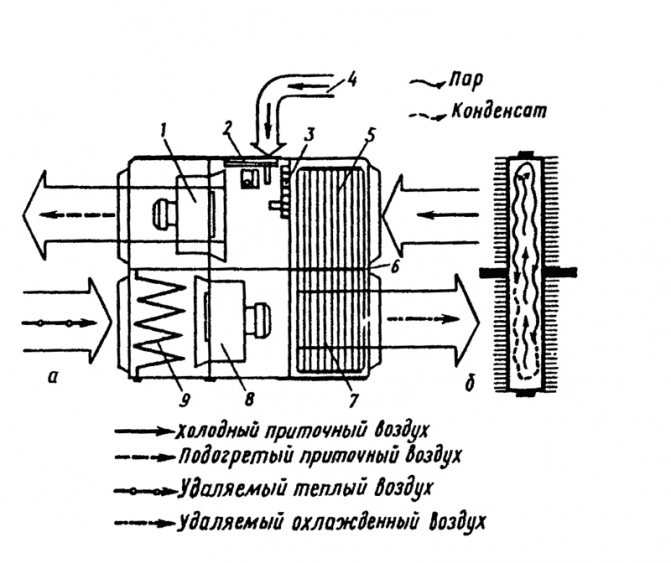
The third method is the simplest - humidification of the outdoor supply air in a steam humidifier (see Figure 12).
1. Determining the parameters of indoor air - (•) B and finding a point on the J-d diagram, see points 1 and 2.
2. Determination of supply air parameters - (•) P see points 3 and 4.
3. From a point with outdoor air parameters - (•) H we draw a line of constant moisture content - dH = const up to the intersection with the supply air isotherm - tP. We get the point - (•) K with the parameters of the heated outside air in the heater.
4. Outdoor air treatment processes on the J-d diagram will be represented by the following lines:
- line NK - the process of heating the supply air in the heater;
- KP line - the process of humidifying heated air with steam.
5. Further, similarly to paragraph 10.
6. The amount of supply air is determined by the formula
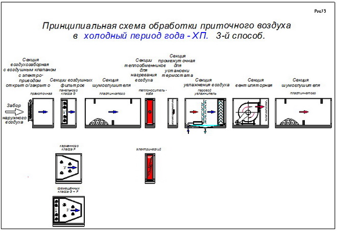
7. The amount of steam for humidifying the heated supply air is calculated by the formula
W=GP(dP - dK), g/h
8. The amount of heat for heating the supply air
Q=GP(JK —JH) = GP x C(tK — tH), kJ/h
where: С = 1.005 kJ/(kg × ºС) – specific heat capacity of air.
To obtain the heat output of the heater in kW, it is necessary to divide Q kJ/h by 3600 kJ/(h × kW).
Schematic diagram of the supply air treatment in the cold period of the year HP, for the 3rd method, see Figure 13.
Such humidification is used, as a rule, for industries: medical, electronic, food, etc.
Accurate heat load calculations
The value of thermal conductivity and heat transfer resistance for building materials
But still, this calculation of the optimal heat load on heating does not give the required calculation accuracy. It does not take into account the most important parameter - the characteristics of the building. The main one is the heat transfer resistance of the material for the manufacture of individual elements of the house - walls, windows, ceiling and floor. They determine the degree of conservation of thermal energy received from the heat carrier of the heating system.


What is heat transfer resistance (R)? This is the reciprocal of thermal conductivity (λ) - the ability of the material structure to transfer thermal energy. Those. the higher the thermal conductivity value, the higher the heat loss. This value cannot be used to calculate the annual heating load, since it does not take into account the thickness of the material (d). Therefore, experts use the heat transfer resistance parameter, which is calculated by the following formula:
Calculation for walls and windows
Heat transfer resistance of residential building walls
There are normalized values of the heat transfer resistance of walls, which directly depend on the region where the house is located.
In contrast to the enlarged calculation of the heating load, you first need to calculate the heat transfer resistance for external walls, windows, the floor of the first floor and the attic. Let's take as a basis the following characteristics of the house:
- Wall area - 280 m². It includes windows - 40 m²;
- The wall material is solid brick (λ=0.56). The thickness of the outer walls is 0.36 m. Based on this, we calculate the TV transmission resistance - R \u003d 0.36 / 0.56 \u003d 0.64 m² * C / W;
- To improve the thermal insulation properties, an external insulation was installed - polystyrene foam 100 mm thick. For him λ=0.036. Accordingly R \u003d 0.1 / 0.036 \u003d 2.72 m² * C / W;
- The overall R value for exterior walls is 0.64 + 2.72 = 3.36 which is a very good indicator of the thermal insulation of the house;
- Heat transfer resistance of windows - 0.75 m² * C / W (double-glazed window with argon filling).
In fact, heat losses through the walls will be:
(1/3.36)*240+(1/0.75)*40= 124 W at 1°C temperature difference
We take the temperature indicators the same as for the enlarged calculation of the heating load + 22 ° С indoors and -15 ° С outdoors. Further calculation must be done according to the following formula:
Ventilation calculation
Then you need to calculate the losses through ventilation. The total air volume in the building is 480 m³. At the same time, its density is approximately equal to 1.24 kg / m³. Those. its mass is 595 kg. On average, the air is renewed five times per day (24 hours). In this case, to calculate the maximum hourly load for heating, you need to calculate the heat losses for ventilation:
(480*40*5)/24= 4000 kJ or 1.11 kWh
Summing up all the obtained indicators, you can find the total heat loss of the house:
In this way, the exact maximum heating load is determined. The resulting value directly depends on the temperature outside. Therefore, to calculate the annual load on the heating system, it is necessary to take into account changes in weather conditions. If the average temperature during the heating season is -7°C, then the total heating load will be equal to:
(124*(22+7)+((480*(22+7)*5)/24))/3600)*24*150(heating season days)=15843 kW
By changing the temperature values, you can make an accurate calculation of the heat load for any heating system.
To the results obtained, it is necessary to add the value of heat losses through the roof and floor. This can be done with a correction factor of 1.2 - 6.07 * 1.2 \u003d 7.3 kW / h.
The resulting value indicates the actual cost of the energy carrier during the operation of the system. There are several ways to regulate the heating load of heating. The most effective of them is to reduce the temperature in rooms where there is no constant presence of residents.This can be done using temperature controllers and installed temperature sensors. But at the same time, a two-pipe heating system must be installed in the building.
To calculate the exact value of heat loss, you can use the specialized program Valtec. The video shows an example of working with it.
Anatoly Konevetsky, Crimea, Yalta
Anatoly Konevetsky, Crimea, Yalta
Dear Olga! Sorry for contacting you again. Something according to your formulas gives me an unthinkable thermal load: Cyr \u003d 0.01 * (2 * 9.8 * 21.6 * (1-0.83) + 12.25) \u003d 0.84 Qot \u003d 1.626 * 25600 * 0.37 * ((22-(-6)) * 1.84 * 0.000001 \u003d 0.793 Gcal / hour According to the enlarged formula above, it turns out only 0.149 Gcal / hour.I can’t understand what’s wrong? Please explain!
Anatoly Konevetsky, Crimea, Yalta
Calculation of heat loss in the house
According to the second law of thermodynamics (school physics), there is no spontaneous transfer of energy from less heated to more heated mini or macro objects. A special case of this law is the “strive” to create a temperature equilibrium between two thermodynamic systems.
For example, the first system is an environment with a temperature of -20°C, the second system is a building with an internal temperature of +20°C. According to the above law, these two systems will tend to balance through the exchange of energy. This will happen with the help of heat losses from the second system and cooling in the first.
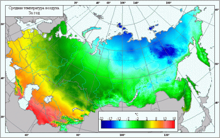 We can definitely say that the ambient temperature depends on the latitude at which the private house is located. And the temperature difference affects the amount of heat leakage from the building (+)
By heat loss is meant an involuntary release of heat (energy) from some object (house, apartment). For an ordinary apartment, this process is not so “noticeable” in comparison with a private house, since the apartment is located inside the building and “adjacent” to other apartments.
In a private house, heat “leaves” to one degree or another through the external walls, floor, roof, windows and doors.
Knowing the amount of heat loss for the most unfavorable weather conditions and the characteristics of these conditions, it is possible to calculate the power of the heating system with high accuracy.
So, the volume of heat leakage from the building is calculated by the following formula:
Q=Qfloor+Qwall+Qwindow+Qroof+QDoor+…+Qi, where
Qi is the volume of heat loss from a uniform type of building envelope.
Each component of the formula is calculated by the formula:
Q=S*∆T/R, where
- Q is thermal leakage, V;
- S is the area of a particular type of structure, sq. m;
- ∆T is the temperature difference between the ambient air and indoors, °C;
- R is the thermal resistance of a certain type of construction, m2*°C/W.
The very value of thermal resistance for actually existing materials is recommended to be taken from auxiliary tables.
In addition, thermal resistance can be obtained using the following relationship:
R=d/k, where
- R - thermal resistance, (m2 * K) / W;
- k is the thermal conductivity of the material, W/(m2*K);
- d is the thickness of this material, m.
In old houses with a damp roof structure, heat leakage occurs through the upper part of the building, namely through the roof and attic. Carrying out measures to insulate the ceiling or mansard roof insulation solve this problem.


If you insulate the attic space and the roof, then the total heat loss from the house can be significantly reduced.
There are several more types of heat losses in the house through cracks in the structures, ventilation system, kitchen hood, opening windows and doors. But it makes no sense to take into account their volume, since they make up no more than 5% of the total number of major heat leaks.
CALCULATION OF ELECTRIC HEATING INSTALLATION
|
2
Figure 1.1 - Layout diagrams of the block of heating elements
1.1 Thermal calculation of heating elementsAs heating elements in electric heaters, tubular electric heaters (TEH) are used, mounted in a single structural unit. The task of thermal calculation of the block of heating elements includes determining the number of heating elements in the block and the actual temperature of the surface of the heating element. The results of the thermal calculation are used to refine the design parameters of the block. The task for the calculation is given in Appendix 1. The power of one heating element is determined based on the power of the heater Pto and the number of heating elements z installed in the heater. The number of heating elements z is taken as a multiple of 3, and the power of one heating element should not exceed 3 ... 4 kW. The heating element is selected according to passport data (Appendix 1). According to the design, blocks are distinguished with a corridor and a staggered layout of heating elements (Figure 1.1).
For the first row of heaters of the assembled heating block, the following condition must be met: оС, (1.2) where tn1 - actual average surface temperature first row heaters, оС; Pm1 is the total power of the heaters of the first row, W; Wed— average heat transfer coefficient, W/(m2оС); Ft1 - total area of the heat-releasing surface of the heaters of the first row, m2; tin - temperature of the air flow after the heater, °C. The total power and the total area of the heaters are determined from the parameters of the selected heating elements according to the formulas where k - the number of heating elements in a row, pcs; Pt, Ft - respectively, power, W, and surface area, m2, of one heating element. Surface area of ribbed heating element where d is the diameter of the heating element, m; la – active length of the heating element, m; hR is the height of the rib, m; a - fin pitch, m For bundles of transversely streamlined pipes, one should take into account the average heat transfer coefficient Wed, since the conditions for heat transfer by separate rows of heaters are different and are determined by the turbulence of the air flow. The heat transfer of the first and second rows of tubes is less than that of the third row. If the heat transfer of the third row of heating elements is taken as unity, then the heat transfer of the first row will be about 0.6, the second - about 0.7 in staggered bundles and about 0.9 - in the in-line from the heat transfer of the third row. For all rows after the third row, the heat transfer coefficient can be considered unchanged and equal to the heat transfer of the third row. The heat transfer coefficient of the heating element is determined by the empirical expression , (1.5) where Nu – Nusselt criterion, - coefficient of thermal conductivity of air, = 0.027 W/(moC); d – diameter of the heating element, m. The Nusselt criterion for specific heat transfer conditions is calculated from the expressions for in-line tube bundles at Re 1103 , (1.6) at Re > 1103 , (1.7) for staggered tube bundles: for Re 1103, (1.8) at Re > 1103 , (1.9) where Re is the Reynolds criterion. The Reynolds criterion characterizes the air flow around the heating elements and is equal to where — air flow velocity, m/s; — coefficient of kinematic viscosity of air, = 18.510-6 m2/s. In order to ensure an effective thermal load of heating elements that does not lead to overheating of the heaters, it is necessary to ensure air flow in the heat exchange zone at a speed of at least 6 m/s. Taking into account the increase in the aerodynamic resistance of the air duct structure and the heating block with an increase in the air flow velocity, the latter should be limited to 15 m/s. Average heat transfer coefficient for in-line bundles for chess beams , (1.12) where n — the number of rows of pipes in the bundle of the heating block. The temperature of the air flow after the heater is where Pto - the total power of heating elements of the heater, kW; — air density, kg/m3; Within is the specific heat capacity of air, Within= 1 kJ/(kgоС); Lv – air heater capacity, m3/s. If condition (1.2) is not met, choose another heating element or change the air velocity taken in the calculation, the layout of the heating block. Table 1.1 - values of the coefficient c Initial dataShare with your friends: |


2
What types are
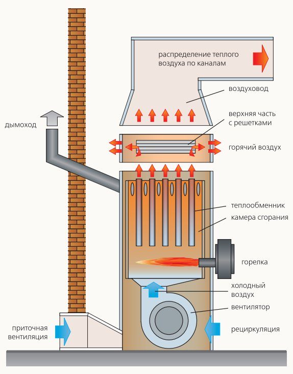
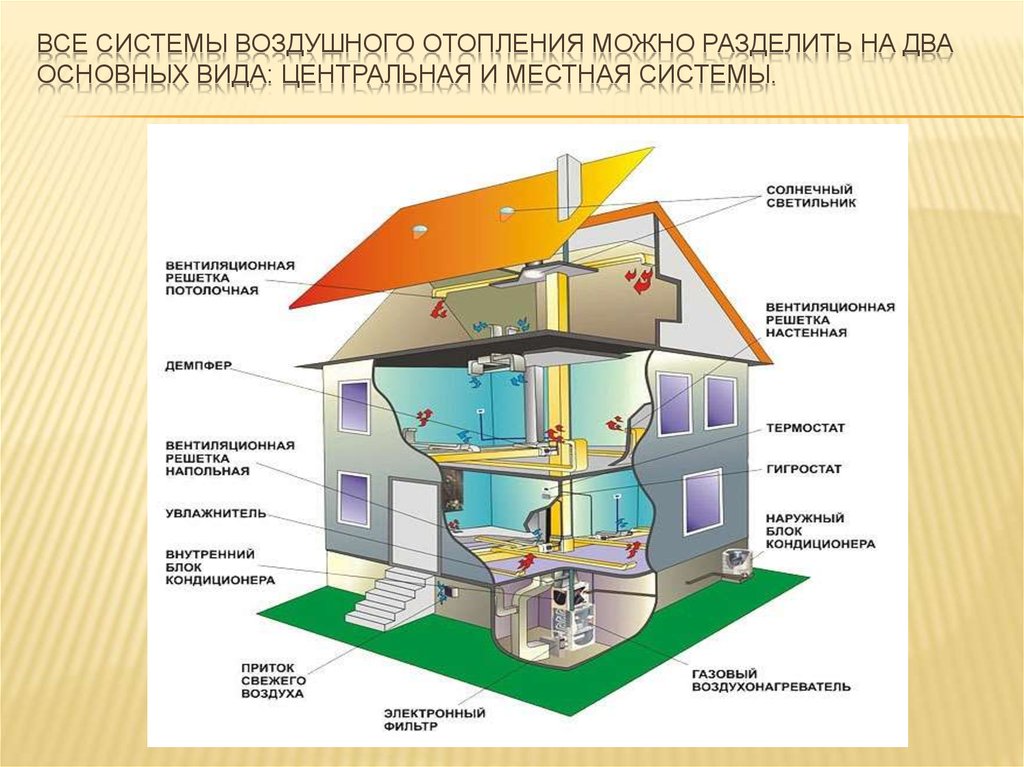
There are two ways to circulate air in the system: natural and forced. The difference is that in the first case, the heated air moves in accordance with the laws of physics, and in the second case, with the help of fans.According to the method of air exchange, the devices are divided into:
- recirculation - use air directly from the room;
- partially recirculating - partially use the air from the room;
- supply air, using air from the street.
Features of the Antares system
The principle of operation of Antares comfort is the same as that of other air heating systems.
The air is heated by the AVH unit and is distributed through the air ducts with the help of fans throughout the premises.
The air returns back through the return ducts, passing through the filter and the collector.
The process is cyclic and goes on endlessly. Mixing with warm air from the house in the heat exchanger, the entire flow goes through the return duct.
Advantages:
- Low noise level. It's all about the modern German fan. The structure of its backward curved blades pushes the air slightly. He does not hit the fan, but as if enveloping. In addition, thick sound insulation AVN is provided. The combination of these factors makes the system almost silent.
- Room heating rate. The fan speed is adjustable, which makes it possible to set the full power and quickly warm the air to the desired temperature. The noise level will rise noticeably in proportion to the speed of the supplied air.
- Versatility. In the presence of hot water, the Antares comfort system is able to work with any type of heater. It is possible to install both water and electric heaters at the same time. This is very convenient: when one power source fails, switch to another.
- Another feature is modularity. This means that Antares comfort is made up of several blocks, which results in weight reduction and ease of installation and maintenance.
With all the advantages, Antares comfort has no drawbacks.
Volcano or Volcano
A water heater and a fan connected together - this is how the heating units of the Polish company Volkano look like. They work from indoor air and do not use outdoor air.
Photo 2. Device from the manufacturer Volcano designed for air heating systems.
The air heated by the thermal fan is evenly distributed through the provided shutters in four directions. Special sensors maintain the desired temperature in the house. Shutdown occurs automatically when the unit is not needed. There are several models of Volkano thermal fans in different sizes on the market.
Features of air-heating units Volkano:
- quality;
- affordable price;
- noiselessness;
- possibility of installation in any position;
- housing made of wear-resistant polymer;
- complete readiness for installation;
- three years warranty;
- economy.
Perfect for heating factory floors, warehouses, large shops and supermarkets, poultry farms, hospitals and pharmacies, sports centers, greenhouses, garage complexes and churches. Wiring diagrams are included to make installation quick and easy.
The sequence of actions when installing air heating
To install an air heating system for a workshop and other industrial premises, the following sequence of actions must be followed:
- Development of a design solution.
- Heating system installation.
- Carrying out commissioning and testing by air and actuation of automation systems.
- Acceptance into operation.
- Exploitation.
Below we consider in more detail each of the stages.
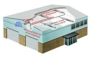
Air heating system design
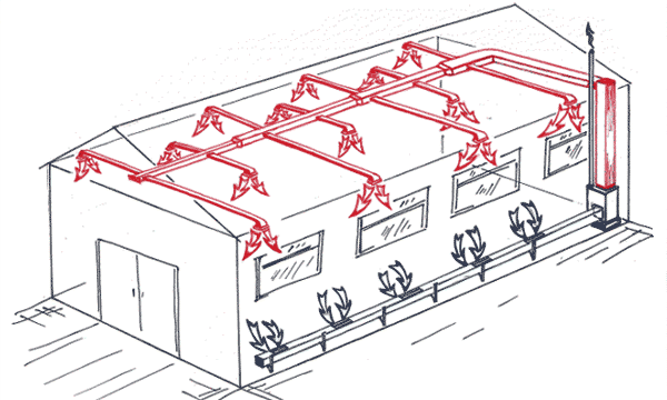
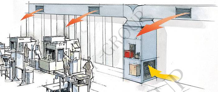
The correct location of heat sources around the perimeter will allow heating the premises in the same volume. Click to enlarge.
Air heating of a workshop or warehouse must be installed in strict accordance with a previously developed design solution.
You don't have to do all the necessary calculations and selection of equipment independently, since errors in design and installation can lead to a malfunction and the appearance of various defects: increased noise level, imbalance in the air supply to the premises, temperature imbalance.
The development of a design solution should be entrusted to a specialized organization, which, based on the technical specifications (or terms of reference) submitted by the customer, will deal with the following technical tasks and issues:
- Determination of heat losses in each room.
- Determination and selection of an air heater of the required power, taking into account the magnitude of heat losses.
- Calculation of the amount of heated air, taking into account the power of the air heater.
- Aerodynamic calculation of the system, made to determine the pressure loss and the diameter of the air channels.
After the completion of the design work, you should proceed to the purchase of equipment, taking into account its functionality, quality, range of operating parameters and cost.
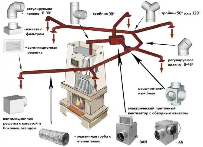
Installation of air heating system
Work on the installation of the air heating system of the workshop can be performed independently (by specialists and employees of the enterprise) or resort to the services of a specialized organization.
When installing the system yourself, it is necessary to take into account some specific features.
Before starting installation, it will not be superfluous to make sure that the necessary equipment and materials are complete.
The layout of the air heating system. Click to enlarge.


At specialized enterprises producing ventilation equipment, you can order air ducts, tie-ins, throttle dampers and other standard products used in the installation of an air heating system for industrial premises.
In addition, the following materials will be needed: self-tapping screws, aluminum tape, mounting tape, flexible insulated air ducts with noise damping function.
When installing air heating, it is necessary to provide for insulation (thermal insulation) of the supply air ducts.
This measure is intended to eliminate the possibility of condensation. When installing the main air ducts, galvanized steel is used, on top of which a self-adhesive foil insulation is glued, with a thickness of 3 mm to 5 mm.
The choice of rigid or flexible air ducts or their combination depends on the type of air heater determined by the design decision.
The connection between the air ducts is carried out using reinforced aluminum tape, metal or plastic clamps.
The general principle of installation of air heating is reduced to the following sequence of actions:
- Carrying out general construction preparatory work.
- Installation of the main air duct.
- Installation of outlet air ducts (distribution).
- Air heater installation.
- Device for thermal insulation of supply air ducts.
- Installation of additional equipment (if necessary) and individual elements: recuperators, grilles, etc.
Application of thermal air curtains
To reduce the volume of air entering the room when opening external gates or doors, in the cold season, special thermal air curtains are used.
At other times of the year they can be used as recirculation units. Such thermal curtains are recommended for use:
- for external doors or openings in rooms with a wet regime;
- at constantly opening openings in the outer walls of structures that are not equipped with vestibules and can be opened more than five times in 40 minutes, or in areas with an estimated air temperature below 15 degrees;
- for external doors of buildings, if they are adjacent to premises without a vestibule, which are equipped with air conditioning systems;
- at openings in internal walls or in partitions of industrial premises in order to avoid the transfer of coolant from one room to another;
- at the gate or door of an air-conditioned room with special process requirements.
An example of calculating air heating for each of the above purposes can serve as an addition to the feasibility study for installing this type of equipment.
The temperature of the air that is supplied to the room by thermal curtains is taken not higher than 50 degrees at external doors, and not more than 70 degrees - at external gates or openings.
When calculating the air heating system, the following values of the temperature of the mixture entering through the external doors or openings (in degrees) are taken:
5 - for industrial premises during heavy work and the location of workplaces no closer than 3 meters to the outer walls or 6 meters from the doors;
8 - for heavy types of work for industrial premises;
12 - during moderate work in industrial premises, or in the lobbies of public or administrative buildings.
14 - for light work for industrial premises.
For high-quality heating of the house, the correct location of the heating elements is necessary. Click to enlarge.
The calculation of air heating systems with thermal curtains is made for various external conditions.
Air curtains at external doors, openings or gates are calculated taking into account wind pressure.
The coolant flow rate in such units is determined from the wind speed and the outside air temperature at parameters B (at a speed of not more than 5 m per second).
In those cases when the wind speed if parameters A are greater than parameters B, then the air heaters should be checked when exposed to parameters A.
The speed of air outflow from slots or external openings of thermal curtains is assumed to be no more than 8 m per second at external doors and 25 m per second at technological openings or gates.
When calculating heating systems with air units, parameters B are taken as the design parameters of the outside air.
One of the systems during non-working hours can operate in standby mode.
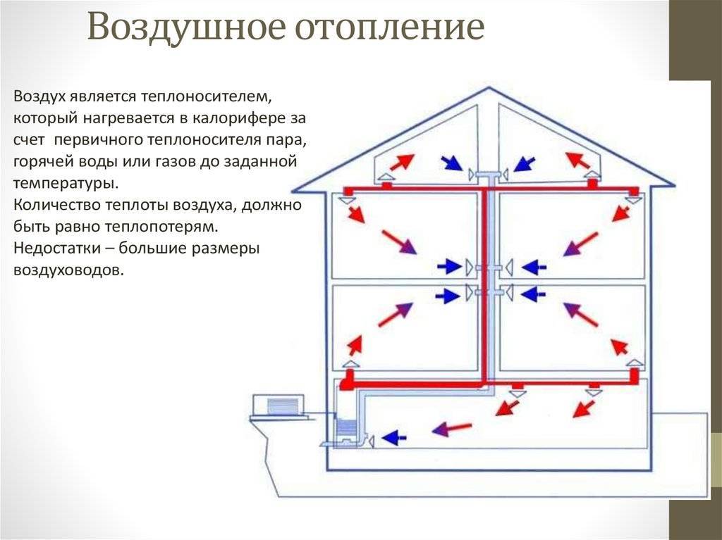
The advantages of air heating systems are:
- Reducing the initial investment by reducing the cost of purchasing heating appliances and laying pipelines.
- Ensuring sanitary and hygienic requirements for environmental conditions in industrial premises due to the uniform distribution of air temperature in large premises, as well as preliminary dedusting and humidification of the coolant.