- Recommended air exchange rates
- Network elements and local resistances
- Calculation table.
- The required diameter of the diaphragm for air ducts.
- Formulas for calculations
- Aerodynamic calculation of air ducts
- The formula for calculating the pressure loss when air moves through the duct:
- Table of specific pressure losses due to friction in the duct.
- Formulas for calculation
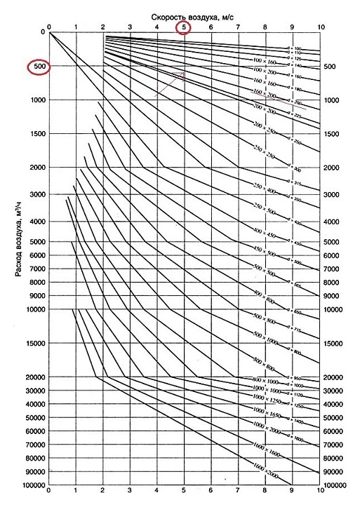
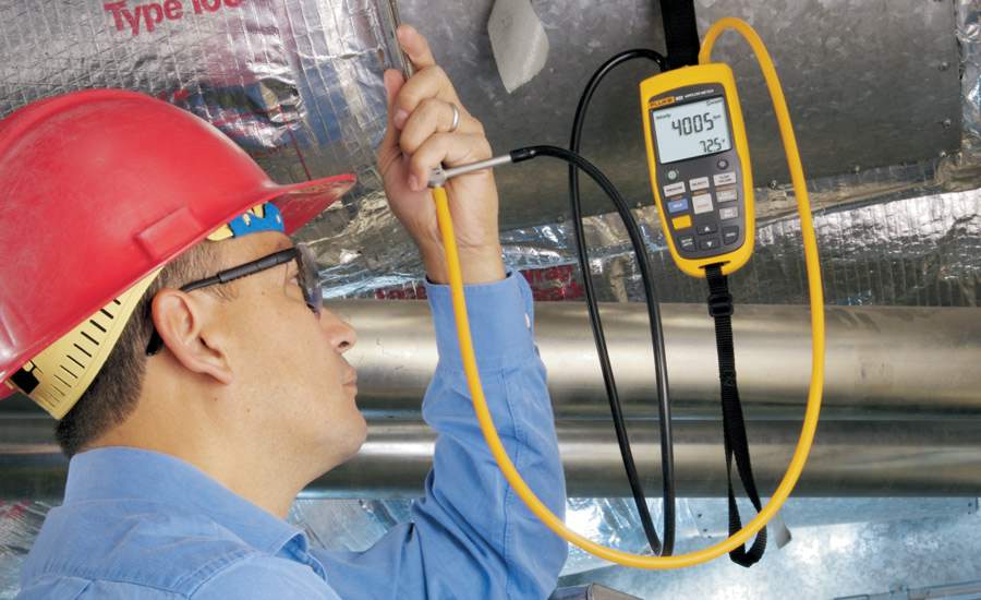
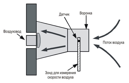
- 4 Determination of air velocity
- Some useful tips for the correct use of devices
- Calculation of air ducts for supply and exhaust systems of mechanical and natural ventilation
- Velocity in the duct
- Air velocity in the duct
- Formula for calculating air speed:
- The formula for calculating the pressure in the duct:
- Other calculators
- Rules for the use of measuring devices
- Air flow calculation
- Section calculation
- Vibration level
- Conclusion
Recommended air exchange rates
As already mentioned, the air flow rate through the ventilation ducts is not standardized. But the SNiP prescribes the recommended values \u200b\u200bof the speed of movement of air masses, which must be guided by when designing ventilation.
The permissible air velocity in the ducts is given in the table:
| Type of air duct and ventilation grille | Type of ventilation scheme | |
|---|---|---|
| Natural | Forced | |
| m/s | ||
| Supply grilles (blinds) | 0.5-1.0 | 2.0-4.0 |
| Supply mine channels | 1.0-2.0 | 2.0-2.6 |
| Horizontal composite (prefabricated) channels | 0.5-1.0 | 2.0-2.5 |
| Vertical channels | 0.5-1.0 | 2.0-2.5 |
| Lattices near the floor | 0.2-0.5 | 2.0-2.5 |
| Lattices at the ceiling | 0.5-1.0 | 1.0-3.0 |
| Exhaust grilles | 0.5-1.0 | 1.5-3.0 |
| Exhaust shaft channels | 1.0-1.5 | 3.0-6.0 |
Maximum recommended airflow rate in residential premises should not exceed 0.3 m/s. Its short-term excess up to 30% is allowed, for example, during repair work.
Network elements and local resistances
Losses on network elements (lattices, diffusers, tees, turns, changes in section, etc.) are also important. For lattices and some elements, these values are specified in the documentation. They can also be calculated by multiplying the coefficient of local resistance (c.m.s.) by the dynamic pressure in it:
Rm. s.=ζ Rd.
Where Rd=V2 ρ/2 (ρ is the air density).
K. m. s. determined from reference books and factory characteristics of products. We summarize all types of pressure losses for each section and for the entire network. For convenience, we will do this in a tabular way.
Calculation table.
The sum of all pressures will be acceptable for this duct network and the branch losses must be within 10% of the total available pressure. If the difference is greater, it is necessary to mount dampers or diaphragms on the outlets. To do this, we calculate the required c.m.s. according to the formula:
ζ= 2Rizb/V2,
where Pizb is the difference between available pressure and branch losses. According to the table, select the diameter of the diaphragm.
The required diameter of the diaphragm for air ducts.
The correct calculation of ventilation ducts will allow you to choose the right fan by choosing from manufacturers according to your criteria. Using the found available pressure and the total air flow in the network, this will be easy to do.
Formulas for calculations
To perform calculations, you need to have some information.To calculate the air flow rate in a duct, the formula ϑ = L / 3600 × F is required, where:
- ϑ is the speed of air masses in the duct;
- L - air flow in a certain area for which calculations are made (measured in m³ \ h);
- F is the area of the air passage channel (measured in m²).
To calculate the airflow, the above formula can be modified to give L = 3600 × F × ϑ.
But there are circumstances when it is difficult or simply there is no time to make such calculations. In such situations, a special calculator for calculating the air velocity in the duct comes to the rescue.
Engineering offices most often use calculators, which are the most accurate. For example, they add more digits to the pi number, calculate the air flow more accurately, calculate the thickness of the walls of the passage, etc.
Thanks to the calculation of the velocity in the air duct, we will be able to accurately calculate not only the amount of air supplied, but also to find out the dynamic pressure on the walls of the channels, the costs through friction, dynamic resistance, etc.
Aerodynamic calculation of air ducts
Aerodynamic calculation of air ducts is one of the main stages in the design of a ventilation system, because it allows you to calculate the cross section of the duct (diameter - for round, and height with width for rectangular).
The cross-sectional area of the duct is selected according to the recommended speed for this case (depends on the air flow and on the location of the calculated section).
F = G/(ρ v), m²
where G is the air flow rate in the calculated section of the duct, kg/сρ is the air density, kg/m³v is the recommended air velocity, m/s (see Table 1)
Table 1. Determining the recommended air velocity in a mechanical ventilation system.


With a ventilation system with natural induction, the air speed is assumed to be 0.2-1 m / s. In some cases, the speed can reach 2 m/s.
The formula for calculating the pressure loss when air moves through the duct:
ΔP = ΔPtr + ΔPm.s. = λ (l/d) (v²/2) ρ + Σξ (v²/2) ρ,
In a simplified form, the formula for air pressure loss in the duct looks like this:
∆P = Rl + Z,
The specific friction pressure loss can be calculated by the formula: R = λ (l/d) (v²/2) ρ, [Pa/M]
l — air duct length, m
Z is the pressure loss at local resistances, PaZ = Σξ (v²/2) ρ,
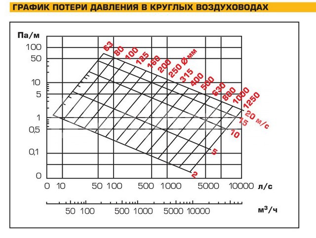
The specific friction pressure loss R can also be determined using the table. It is enough to know the air flow in the area and the diameter of the duct.
Table of specific pressure losses due to friction in the duct.
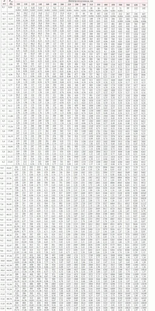
The top number in the table is the air flow rate and the bottom number is the specific friction pressure loss (R).
If the duct is rectangular, then the values in the table are searched based on the equivalent diameter. The equivalent diameter can be determined using the following formula:
deq = 2ab/(a+b)
where a and b are the width and height of the duct.
This table shows the values of specific pressure losses at an equivalent roughness coefficient of 0.1 mm (coefficient for steel air ducts). If the air duct is made of another material, then the tabular values \u200b\u200bmust be adjusted according to the formula:
∆P = Rlβ + Z,
where R is the specific pressure loss due to friction, l is the length of the duct, mZ is the pressure loss due to local resistances, Paβ is a correction factor that takes into account the roughness of the duct. Its value can be taken from the table below.
It is also necessary to take into account pressure losses due to local resistances.The coefficients of local resistances, as well as the method for calculating pressure losses, can be taken from the table in the article “Calculation of pressure losses in local resistances of the ventilation system. Coefficients of local resistances.» And the dynamic pressure is determined from the table of specific friction pressure losses (table 1).
To determine the dimensions of air ducts under natural draft, use the amount of available pressure. The available pressure is the pressure that is created due to the temperature difference between the supply and outgoing air, in other words, the gravitational pressure.
The dimensions of air ducts in a natural ventilation system are determined using the equation:
where ∆Prasp — available pressure, Pa
0.9 - increasing factor for power reserve
n is the number of sections of air ducts on the calculated branch
With a ventilation system with mechanical air induction, the air ducts are selected according to the recommended speed. Next, the pressure losses are calculated according to the calculated branch, and according to the ready-made data (air flow and pressure losses), a fan is selected.
Formulas for calculation
To carry out all the necessary calculations, you need to have some data. To calculate air speed, you need the following formula:
ϑ= L / 3600*F, where
ϑ - air flow velocity in the pipeline of the ventilation device, measured in m/s;
L is the flow rate of air masses (this value is measured in m3/h) in that section of the exhaust shaft for which the calculation is made;
F is the cross-sectional area of the pipeline, measured in m2.
According to this formula, the air velocity in the duct is calculated, and its actual value.
All other missing data can be deduced from the same formula.For example, to calculate airflow, the formula needs to be converted as follows:
L = 3600 x F x ϑ.
In some cases, such calculations are difficult to perform or there is not enough time. In this case, you can use a special calculator. There are many similar programs on the Internet. For engineering bureaus, it is better to install special calculators that are more accurate (they subtract the pipe wall thickness when calculating its cross-sectional area, put more characters in pi, calculate more accurate air flow, etc.).


Air flow
4 Determination of air velocity
Knowing the multiplicity of air masses, it is easy to calculate the air velocity in the duct during natural ventilation. First you need to find out the cross-sectional area of \u200b\u200bthe ducts. To do this, the square of the radius of the duct section must be multiplied by the number "pi".
Air ducts must have a certain size and shape. Having determined the cross-section of the air duct, it is possible to calculate the diameter of the air duct required for a particular room. The expression D = 1000*√(4*S/π) will help with this. In him:
- D is the diameter of the duct section.
- S is the cross-sectional area of the air channels.
- π is a mathematical constant equal to 3.14.
In accordance with the standards, the minimum size of a rectangular duct is 100 mm x 150 mm, the maximum is 2000 mm x 2000 mm. Such designs have a more ergonomic shape, it is easier to install them tightly against the wall and mask the pipes on the ceiling or above the kitchen mezzanines.
Round products differ from rectangular ones in that they create less air resistance. Therefore, they have a minimum noise level.
Using the formula V = L / 3600 * S and parameters such as air flow (L) and duct area, you can calculate natural ventilation. An example calculation would be:
- D = 400 mm.
- W = 20 m³.
- N = 6 m3/h.
- L = 120 m³.
It is established that this indicator should not exceed 0.3 m/s. An exception is made only for the period of temporary repair work or installation of construction equipment. At this time, the standards can be increased by a maximum of 30%.
If there are two ventilation systems in the room, then the speed of each of them is calculated in such a way that it is sufficient to provide half the area with clean air.
In the event of unforeseen situations (for example, due to fire safety requirements), it is necessary to change the air speed abruptly or stop the operation of the ventilation system. To do this, special valves and cut-off valves are installed in the channels and in the transitional sections.
Some useful tips for the correct use of devices
If the air flow in the duct is characterized by an increased level of dust content, it is better not to use a hot-wire anemometer and Pitot tube in this case. Since the hole in the tube that receives the total pressure of the flow has a small diameter, it can quickly become clogged when exposed to polluted air.
Hot-wire anemometers are not suitable for operation at high air speeds (more than 20 m/s). The fact is that the main temperature sensor, which is characterized by increased sensitivity, can simply collapse under strong air pressure.
The use of control and measuring devices for determining the air flow must be carried out strictly in the nominal temperature ranges specified in the passports of the devices.
In gas ducts (air ducts in which mainly heated air flows), it is recommended to use pneumometric tubes, the body of which is made of stainless steel. The use of equipment with plastic components in these pipes is undesirable due to the possible deformation of the body under the influence of high temperatures.
When measuring speed and air flow, it is necessary to ensure that the sensitive sensor of the probe is always oriented exactly towards the air flow. Failure to comply with this requirement leads to distortion of the measurement results. Moreover, distortions and inaccuracies will be the greater, the greater the degree of deviation of the sensor from the ideal position.
Thus, the right choice of instrumentation to determine the flow of air masses in the air duct and their proper use during work will allow specialists to form an objective picture of the ventilation of the premises
This aspect is of particular importance when it comes to residential premises.
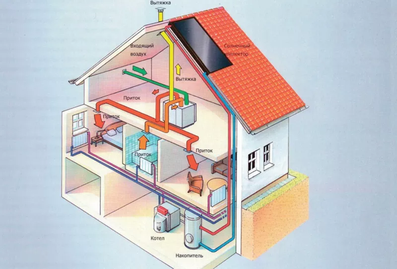
Calculation of air ducts for supply and exhaust systems of mechanical and natural ventilation
Aerodynamic
calculation of air ducts is usually reduced
to determine the dimensions of their transverse
section,
as well as pressure losses on individual
plots
and in the system as a whole. Can be determined
expenses
air for given dimensions of air ducts
and known differential pressure in the system.
At
aerodynamic calculation of air ducts
ventilation systems are usually neglected
compressibility
moving air and enjoy
overpressure values, assuming
for a conditional
zero atmospheric pressure.
At
movement of air through the duct in any
transverse
flow cross section there are three types
pressure:static,
dynamic
and complete.
static
pressure
determines the potential
energy 1 m3
air in the section under consideration (pst
equal to the pressure on the walls of the duct).
dynamic
pressure
is the kinetic energy of the flow,
related to 1 m3
air, determined
according to the formula:
(1)
where
– density
air, kg/m3;
- speed
air movement in the section, m/s.
Complete
pressure
equal to the sum of static and dynamic
pressure.
(2)
Traditionally
when calculating the duct network, it is used
the term "loss
pressure”
("losses
flow energy”).
Losses
pressure (full) in the ventilation system
are made up of friction losses and
losses in local
resistances (see: Heating and
ventilation, part 2.1 “Ventilation”
ed. V.N. Bogoslovsky, M., 1976).


Losses
friction pressures are determined by
formula
Darcy:
(3)
where
- coefficient
friction resistance, which
calculated by the universal formula
HELL. Altshulya:
(4)
where
– Reynolds criterion; K - height
roughness projections (absolute
roughness).
engineering pressure loss calculations
friction
,
Pa (kg/m2),
in an air duct with a length /, m, are determined
by expression
(5)
where
– losses
pressure per 1 mm of duct length,
Pa/m [kg/(m2
* m)].
For
definitions Rdrawn up
tables and nomograms. Nomograms (Fig.
1 and 2) are built for the conditions: form sections
duct circle diameter,
air pressure 98 kPa (1 atm), temperature
20°C, roughness = 0.1 mm.
For
calculation of air ducts and channels
rectangular sections are used
tables and nomograms
for round ducts, introducing at
this
equivalent diameter of a rectangular
duct, in which the pressure loss
for friction in
round
and rectangular
~
air ducts are equal.
AT
design practice received
Spread
three types of equivalent diameters:
■ by speed
at
parity of speeds
■ by
consumption
at
cost equity
■ by
cross-sectional area
if equal
cross-sectional areas
At
calculation of air ducts with roughness
walls,
different from that provided for in
tables or nomograms (K = OD mm),
make a correction to
tabular value of specific losses
pressure on
friction:
(6)
where
- tabular
specific pressure loss value
for friction;
- coefficient
taking into account the roughness of the walls (Table 8.6).
Losses
pressure in local resistances. AT
places of rotation of the duct, when dividing
and merger
flows in tees, when changing
sizes
air duct (expansion - in the diffuser,
constriction - in the confuser), at the entrance to
air duct or
canal and exit from it, as well as in places
installations
control devices (throttles,
gates, diaphragms) there is a drop
flow pressure
moving air. In the specified
places going on
restructuring of air velocity fields in
air duct and the formation of vortex zones
at the walls, which is accompanied
loss of flow energy. alignment
flow occurs at some distance
after passing
these places. Conditionally, for convenience
aerodynamic calculation, loss
pressure in local
resistances are considered concentrated.
Losses
pressure in local resistance
determined
according to the formula
(7)
where
–
local resistance coefficient
(usually,
in some cases there is
negative value, when calculating
should
take into account the sign).
Ratio refers to
to top speed
in the narrow section of the section or speed
in section
section with a lower flow rate (in a tee).
In tables
local resistance coefficients
indicates which speed it refers to.


Losses
pressure in local resistances
plot, z,
calculated by the formula
(8)
where
- sum
local resistance coefficients
Location on.
General
pressure loss in the duct section
length,
m, in the presence of local resistances:
(9)
where
– losses
pressure per 1 m of duct length;
– losses
pressure in local resistances
site.
Velocity in the duct
Air velocity in the duct
Here are the formulas for calculating the air velocity and pressure in the duct (round or rectangular section) depending on the air flow and cross-sectional area. For a quick calculation, you can use the online calculator.
Formula for calculating air speed:
where W is the flow rate, m/h Q is the air flow rate, m3/h S is the cross-sectional area of the duct, m2* Note: to convert the speed from m/h to m/s, the result must be divided by 3600
The formula for calculating the pressure in the duct:
where P is the total pressure in the duct, Pa Pst — static pressure in the air duct, equal to atmospheric pressure, Pa p — air density, kg/m3W — flow velocity, m/s * Note: to convert pressure from Pa to atm.multiply the result by 10.197*10-6 (technical atmosphere) or 9.8692*10-6 (physical atmosphere)
airflow speed 88.4194 m/s
air duct pressure 102 855.0204 Pa (1.0488 atm)
Other calculators
Cube Volume and Surface Area CalculatorCylinder Volume and Surface Area CalculatorPipe Volume Calculator
Source
Rules for the use of measuring devices
When measuring the air flow rate and its flow rate in the ventilation and air conditioning system, the correct selection of devices and compliance with the following rules for their operation are required.
This will allow you to get accurate results of the calculation of the duct, as well as to make an objective picture of the ventilation system.
Follow the temperature regime, which is indicated in the device passport. Also keep an eye on the position of the probe sensor. It must always be oriented exactly towards the air flow.
If you do not follow this rule, the measurement results will be distorted. The greater the deviation of the sensor from the ideal position, the higher the error will be.
Air flow calculation
It is important to correctly calculate the cross-sectional area of any shape, both round and rectangular. If the size is not suitable, it will not be possible to achieve the desired air balance.
Too much air duct will take up too much space. This will reduce the area in the room, cause discomfort to residents. If the calculation is incorrect and a very small channel size is chosen, strong drafts will be observed. This is due to a strong increase in airflow pressure.
Section calculation
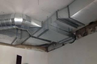 When a round duct changes into a square duct, the speed will change
To calculate the speed at which air will pass through the pipe, you need to determine the cross-sectional area.The following formula is used for calculation S=L/3600*V, where:
- S is the cross-sectional area;
- L - air consumption in cubic meters per hour;
- V is the speed in meters per second.
For round air ducts, it is necessary to determine the diameter using the formula: D = 1000*√(4*S/π).
If the duct is going to be rectangular instead of round, the length and width should be determined instead of the diameter. When installing such an air duct, an approximate cross section is taken into account. It is calculated by the formula: a * b \u003d S, (a - length, b - width).


There are approved standards according to which the ratio of width and length should not exceed 1: 3. It is also recommended to use tables with typical dimensions offered by duct manufacturers.
Vibration level

Vibration is a phenomenon that, along with noise, is always present in ducts if a forced ventilation scheme is used.
Its value depends on the following factors:
- cross-sectional dimensions of air channels;
- the material that was used to make the ventilation pipes;
- composition and quality of gaskets between duct pipes;
- the speed of air movement in the channels of the ventilation system.
Fan power is closely related to the maximum vibration value.
Regulatory indicators that must be taken into account when calculating the parameters of air ducts and choosing the type of ventilation devices are shown in the table:
| Maximum permissible values of local vibration | Maximum permissible values of local vibration | |||
|---|---|---|---|---|
| In terms of vibration acceleration | In terms of vibration velocity | |||
| m/s | dB | m/s x 10-2 | dB | |
| 8 | 1.4 | 73 | 2.8 | 115 |
| 16 | 1.4 | 73 | 1.4 | 109 |
| 31.5 | 2.7 | 79 | 1.4 | 109 |
| 63 | 5.4 | 85 | 1.4 | 109 |
| 125 | 10.7 | 91 | 1.4 | 109 |
| 250 | 21.3 | 97 | 1.4 | 109 |
| 500 | 42.5 | 103 | 1.4 | 109 |
| 1000 | 85.0 | 109 | 1.4 | 109 |
| Adjusted and equivalently adjusted values and their levels | 2.0 | 76 | 2.0 | 112 |
If the ventilation design is done correctly, the air flow velocity in the air passages should not affect the change in noise and vibration levels in the system.
Conclusion
This simple calculation is part of the aerodynamic calculation of the ventilation and air conditioning system. Such calculations are performed in specialized programs or, for example, in Excel.


