- Save and multiply!
- Calculation of the air heating system - a simple technique
- General calculations
- Boiler
- Expansion tank
- Feasibility study of the project
- Classification of water heating systems
- Calculation example
- Calculation for heating radiators per area
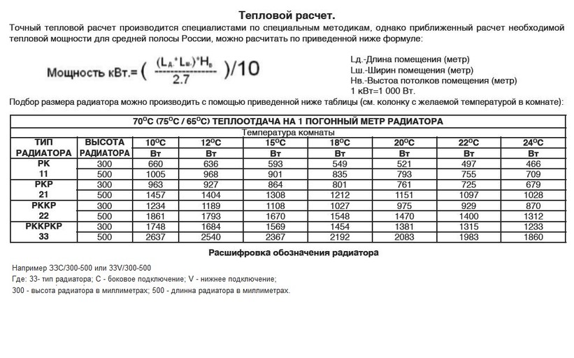
- Enlarged calculation
- Accurate calculation
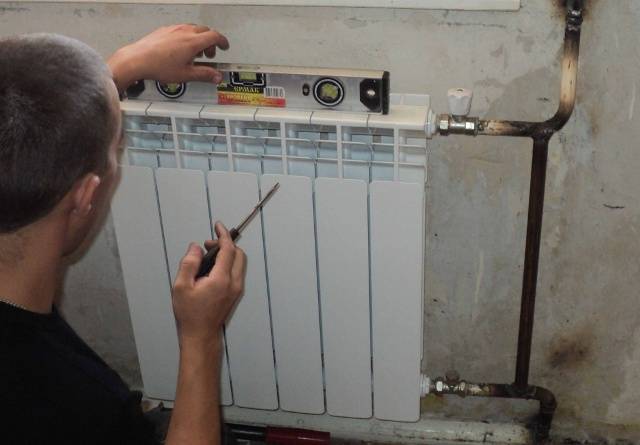
- Modern heating elements
- Calculation of the power of the heating boiler
- Initial data for calculation
Save and multiply!
This is how the Pipeline motto can be formulated in the development and implementation of a new generation hydraulic calculation program - a reliable modern universal system of mass application and moderate cost. What exactly do we want to preserve and what to increase?
It is necessary to preserve those advantages of the program that have been incorporated into it since its inception and developed during subsequent improvement:
- an accurate, modern and proven calculation model underlying the program, including a detailed analysis of flow regimes and local resistances;
- high counting speed, allowing the user to instantly calculate various options for the calculation scheme;
- the possibilities of design calculation incorporated in the program (selection of diameters);
- the possibility of automatic calculation of the necessary thermophysical properties of a wide range of transported products;
- simplicity of an intuitive user interface;
- sufficient versatility of the program, allowing it to be used not only for technological, but also for other types of pipelines;
- moderate cost of the program, which is within the power of a wide range of design organizations and departments.
At the same time, we intend to radically increase the capabilities of the program and the number of regular users by eliminating shortcomings and adding to its functionality in the following main areas:
- Software and functional integration in all its aspects: from a set of specialized and poorly integrated programs, one should move to a single, modular structure program for hydraulic calculations that provides thermal calculation, accounting for heating satellites and electric heating, calculation of pipes of arbitrary section (including gas ducts), calculation and selection of pumps , other equipment, calculation and selection of control devices;
- ensuring software integration (including data transfer) with other programs of NTP "Truboprovod", primarily with the programs "Isolation", "Predvalve", STARS;
- integration with various graphic CAD systems, primarily intended for the design of technological installations, as well as underground pipelines;
- integration with other systems of technological calculation (primarily with systems for modeling technological processes HYSYS, PRO / II and similar) using the international standard CAPE OPEN (support for Thermo and Unit protocols) .
Improving the usability of the user interface. In particular:
- provision of graphical input and editing of the calculation scheme;
graphical representation of calculation results (including piezometer).
Expansion of the program functions and its applicability for the calculation of various types of pipelines. Including:
- providing calculation of pipelines of arbitrary topology (including ring systems), which will allow the program to be used for calculating external engineering networks;
providing the ability to set and take into account when calculating the environmental conditions that change along the course of an extended pipeline (soil and laying parameters, thermal insulation, etc.), which will make it possible to use the program more widely for calculating main pipelines;
implementation of the recommended industry standards and methods in the program hydraulic calculation of gas pipelines (SP 42-101-2003), heating networks (SNiP 41-02-2003), main oil pipelines (RD 153-39.4-113-01), oilfield pipelines (RD 39-132-94), etc.
calculation of multiphase flows, which is important for pipelines tying oil and gas fields.
Expansion of the design functions of the program, solving on its basis the problems of optimizing the parameters of complex pipeline systems and the optimal choice of equipment.
Calculation of the air heating system - a simple technique
Designing air heating is not an easy task. To solve it, it is necessary to find out a number of factors, the independent determination of which can be difficult. RSV specialists can make for you a preliminary project for air heating of a room based on GREEERS equipment free of charge.
An air heating system, like any other, cannot be created at random. To ensure the medical standard of temperature and fresh air in the room, a set of equipment is required, the choice of which is based on an accurate calculation.There are several methods for calculating air heating, of varying degrees of complexity and accuracy. A common problem in calculations of this type is the lack of account for the influence of subtle effects, which are not always possible to foresee.
Therefore, to make an independent calculation, not being a specialist in the field of heating and ventilation, is fraught with errors or miscalculations. However, you can choose the most affordable method based on the choice of heating system power.
Formula for determining heat loss:
Q=S*T/R
Where:
- Q is the amount of heat loss (W)
- S - the area of all structures of the building (premises)
- T is the difference between internal and external temperatures
- R - thermal resistance of enclosing structures
Example:
The building with an area of 800 m2 (20 × 40 m), a height of 5 m, has 10 windows measuring 1.5 × 2 m. Find the area of structures:
800 + 800 = 1600 m2 (floor and ceiling area)
1.5 × 2 × 10 = 30 m2 (window area)
(20 + 40) × 2 × 5 = 600 m2 (wall area). We subtract from here the area of the windows, we get the “clean” area of \u200b\u200bthe walls 570 m2
In the tables of SNiP we find the thermal resistance of concrete walls, floors and floors and windows. You can define it yourself by the formula:
Where:
- R - thermal resistance
- D - material thickness
- K - coefficient of thermal conductivity
For simplicity, we will take the thickness of the walls and floor with the ceiling to be the same, equal to 20 cm. Then the thermal resistance will be 0.2 m / 1.3 \u003d 0.15 (m2 * K) / W
We select the thermal resistance of windows from the tables: R \u003d 0.4 (m2 * K) / W
Let's take the temperature difference as 20°С (20°С inside and 0°С outside).
Then for the walls we get
- 2150 m2 × 20°С / 0.15 = 286666=286 kW
- For windows: 30 m2 × 20 ° C / 0.4 \u003d 1500 \u003d 1.5 kW.
- Total heat loss: 286 + 1.5 = 297.5 kW.
This is the amount of heat loss that must be compensated with the help of air heating with a power of about 300 kW
It is noteworthy that when using floor and wall insulation, heat loss is reduced by at least an order of magnitude.
General calculations
It is necessary to determine the total heating capacity so that the power of the heating boiler is sufficient for high-quality heating of all rooms. Exceeding the permissible volume can lead to increased wear of the heater, as well as significant energy consumption.

The required amount of heating medium is calculated according to the following formula: Total volume = V boiler + V radiators + V pipes + V expansion tank
Boiler
The calculation of the power of the heating unit allows you to determine the boiler capacity indicator. To do this, it is enough to take as a basis the ratio at which 1 kW of thermal energy is sufficient to efficiently heat 10 m2 of living space. This ratio is valid in the presence of ceilings, the height of which is not more than 3 meters.
As soon as the boiler power indicator becomes known, it is enough to find a suitable unit in a specialized store. Each manufacturer indicates the volume of equipment in the passport data.
Therefore, if the correct power calculation is performed, there will be no problems with determining the required volume.
To determine the sufficient volume of water in the pipes, it is necessary to calculate the cross section of the pipeline according to the formula - S = π × R2, where:
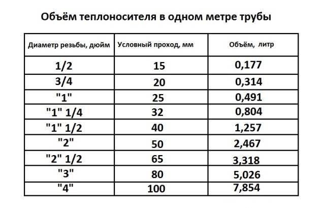
- S - cross section;
- π is a constant constant equal to 3.14;
- R is the inner radius of the pipes.
Having calculated the value of the cross-sectional area of \u200b\u200bthe pipes, it is enough to multiply it by the total length of the entire pipeline in the heating system.
Expansion tank
It is possible to determine what capacity the expansion tank should have, having data on the coefficient of thermal expansion of the coolant. For water, this indicator is 0.034 when heated to 85 °C.
When performing the calculation, it is enough to use the formula: V-tank \u003d (V syst × K) / D, where:
- V-tank - the required volume of the expansion tank;
- V-syst - the total volume of liquid in the remaining elements of the heating system;
- K is the expansion coefficient;
- D - the efficiency of the expansion tank (indicated in the technical documentation).
Currently, there is a wide variety of individual types of radiators for heating systems. In addition to functional differences, they all have different heights.
To calculate the volume of working fluid in radiators, you must first calculate their number. Then multiply this amount by the volume of one section.
You can find out the volume of one radiator using the data from the technical data sheet of the product. In the absence of such information, you can navigate according to the average parameters:
- cast iron - 1.5 liters per section;
- bimetallic - 0.2-0.3 l per section;
- aluminum - 0.4 l per section.
The following example will help you understand how to correctly calculate the value. Let's say there are 5 radiators made of aluminum. Each heating element contains 6 sections. We make the calculation: 5 × 6 × 0.4 \u003d 12 liters.
As you can see, the calculation of the heating capacity comes down to calculating the total value of the four above elements.
Not everyone can determine the required capacity of the working fluid in the system with mathematical accuracy.Therefore, not wanting to perform the calculation, some users act as follows. To begin with, the system is filled by about 90%, after which the performance is checked. Then bleed the accumulated air and continue filling.

During the operation of the heating system, a natural decrease in the level of the coolant occurs as a result of convection processes. In this case, there is a loss of power and productivity of the boiler. This implies the need for a reserve tank with a working fluid, from where it will be possible to monitor the loss of coolant and, if necessary, replenish it.
Feasibility study of the project
Choice
one or another design solution -
the task is usually multifactorial. In
In all cases, there are a large number
possible solutions to the problem
tasks, since any system of TG and V
characterizes a set of variables
(a set of system equipment, various
its parameters, sections of pipelines,
the materials from which they are made
etc.).
AT
In this section, we compare 2 types of radiators:
Rifar
Monolit
350 and Sira
RS
300.
To
determine the cost of the radiator,
Let's make their thermal calculation for the purpose
specification of the number of sections. Calculation
Rifar radiator
Monolit
350 is given in section 5.2.
Classification of water heating systems
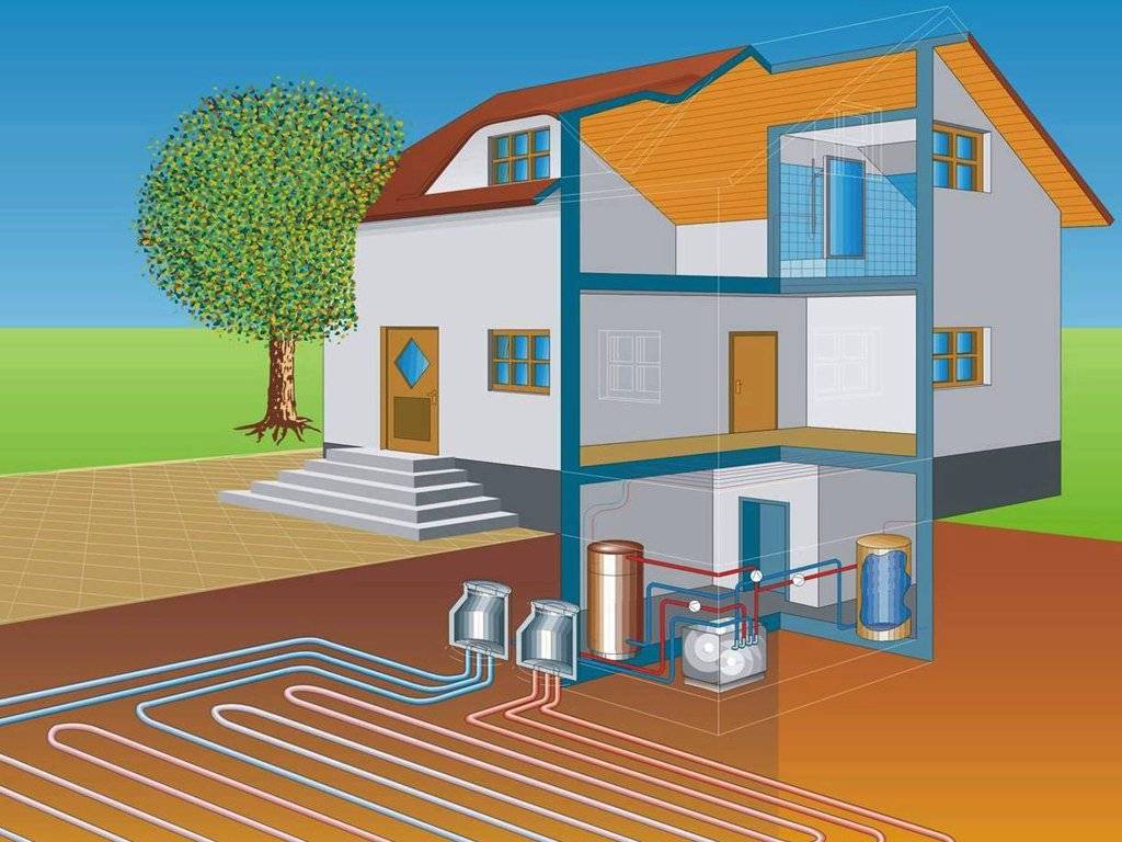
Depending on the location of the place of heat generation, water heating systems are divided into centralized and local. In a centralized manner, heat is supplied, for example, to apartment buildings, all kinds of institutions, enterprises and other objects.
In this case, heat is generated in CHP (combined heat and power plants) or boiler houses, and then delivered to consumers using pipelines.
Local (autonomous) systems provide heat, for example, private houses. It is produced directly at the heat supply facilities themselves. For this purpose, furnaces or special units operating on electricity, natural gas, liquid or solid combustible materials are used.
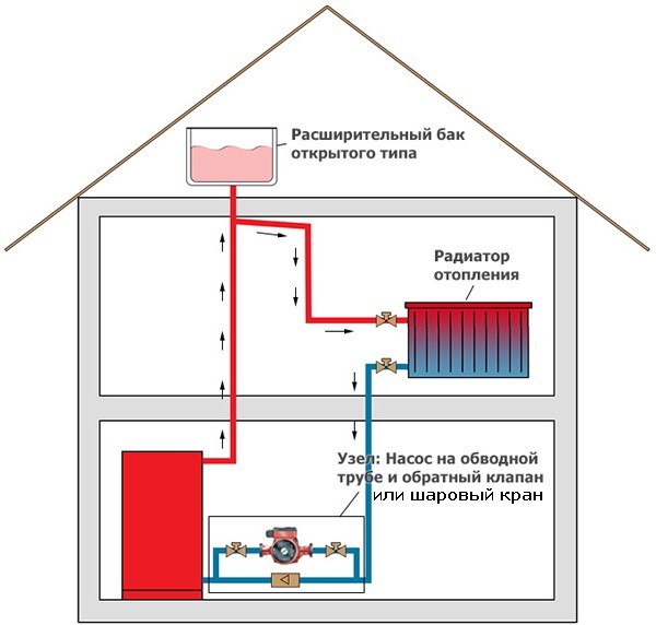
Depending on the way in which the movement of water masses is ensured, heating can be with forced (pumping) or natural (gravitational) movement of the coolant. Systems with forced circulation can be with ring schemes and with schemes of primary-secondary rings.
 Different water heating systems differ from each other in the type of wiring and the method of connecting devices. Combines their type of coolant that transfers heat to heating devices (+)
In accordance with the direction of movement of water in the mains of the supply and return types, heat supply can be with passing and dead-end movement of the coolant. In the first case, water moves in the mains in one direction, and in the second - in different directions.
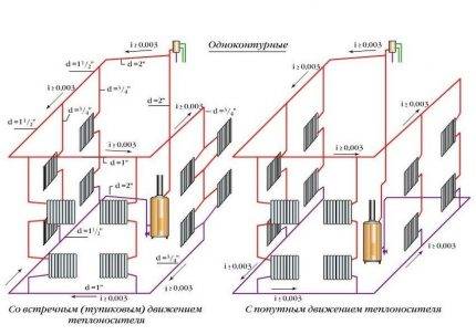 In the direction of movement of the coolant, the systems are divided into dead-end and counter. In the first, the flow of heated water is directed in the direction opposite to the direction of the cooled water. In passing schemes, the movement of the heated and cooled coolant occurs in the same direction (+)
Heating pipes can be connected to heating devices in different schemes. If the heaters are connected in series, such a scheme is called a single-pipe circuit, if in parallel - a two-pipe circuit.
There is also a bifilar scheme, in which all the first halves of the devices are first connected in series, and then, to ensure the reverse outflow of water, their second halves.
The location of the pipes connecting the heating devices gave the name to the wiring: they distinguish between its horizontal and vertical varieties. According to the assembly method, collector, tee and mixed pipelines are distinguished.
Schemes of heating systems with upper and lower wiring differ in the location of the supply line. In the first case, the supply pipe is laid above the devices that receive the heated coolant from it, in the second case, the pipe is laid below the batteries (+)
In those residential buildings where there are no basements, but there is an attic, heating systems with overhead wiring are used. In them, the supply line is located above the heating appliances.

For buildings with a technical basement and a flat roof, heating with a lower wiring is used, in which the water supply and drainage lines are located below the heating devices.
There is also a wiring with an "overturned" circulation of the coolant. In this case, the heat supply return line is located below the devices.
According to the method of connecting the supply line to the heating devices, systems with upper wiring are divided into schemes with two-way, one-way and overturned movement of the coolant
Calculation example
The correction factors in this case will be equal to:
- K1 (two-chamber double-glazed window) = 1.0;
- K2 (walls made of timber) = 1.25;
- K3 (glazing area) = 1.1;
- K4 (at -25 ° C -1.1, and at 30 ° C) = 1.16;
- K5 (three outer walls) = 1.22;
- K6 (a warm attic from above) = 0.91;
- K7 (room height) = 1.0.
As a result, the total heat load will be equal to: In the case where a simplified calculation method based on the calculation of the heating power according to the area would be used, the result would be completely different: An example of calculating the thermal power of a heating system on video:
Calculation for heating radiators per area
Enlarged calculation
If for 1 sq.m. area requires 100 W of thermal energy, then a room of 20 sq.m. should receive 2,000 watts. A typical eight-section radiator puts out about 150 watts of heat. We divide 2,000 by 150, we get 13 sections. But this is a rather enlarged calculation of the thermal load.
Accurate calculation
The exact calculation is carried out according to the following formula: Qt = 100 W/sq.m. × S(rooms) sq.m. × q1 × q2 × q3 × q4 × q5 × q6× q7, where:
- q1 - type of glazing: ordinary = 1.27; double = 1.0; triple = 0.85;
- q2 - wall insulation: weak or absent = 1.27; wall laid out in 2 bricks = 1.0, modern, high = 0.85;
- q3 - the ratio of the total area of window openings to the floor area: 40% = 1.2; 30% = 1.1; 20% - 0.9; 10% = 0.8;
- q4 - minimum outdoor temperature: -35 C = 1.5; -25 C \u003d 1.3; -20 C = 1.1; -15 C \u003d 0.9; -10 C = 0.7;
- q5 - the number of external walls in the room: all four = 1.4, three = 1.3, corner room = 1.2, one = 1.2;
- q6 - type of calculation room above the calculation room: cold attic = 1.0, warm attic = 0.9, residential heated room = 0.8;
- q7 - ceiling height: 4.5 m = 1.2; 4.0 m = 1.15; 3.5 m = 1.1; 3.0 m = 1.05; 2.5 m = 1.3.
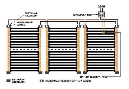
Modern heating elements
It is extremely rare today to see a house in which heating is carried out exclusively by air sources. These include electric heating devices: fan heaters, radiators, ultraviolet radiation, heat guns, electric fireplaces, stoves.It is most rational to use them as auxiliary elements with a stable main heating system. The reason for their "minority" is the rather high cost of electricity.
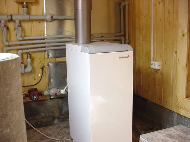
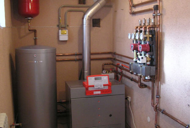
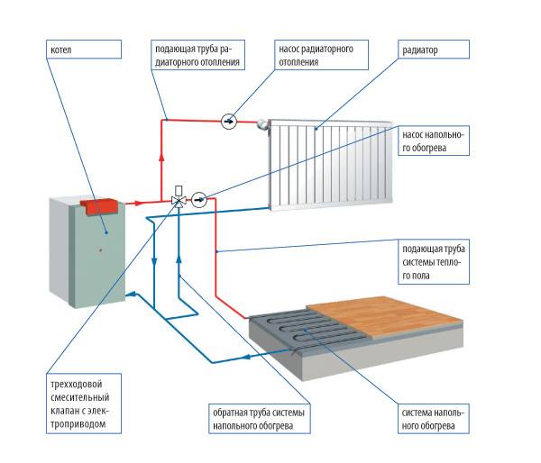 The main elements of the heating system
When planning any type of heating system, it is important to know that there are generally accepted recommendations regarding the power density of the heating boiler used. In particular, for the northern regions of the country, it is approximately 1.5 - 2.0 kW, in the central - 1.2 - 1.5 kW, in the southern - 0.7 - 0.9 kW
In this case, before calculating the heating system, to calculate the optimal boiler power, use the formula:
W cat. = S*W / 10.
Calculation of the heating system of buildings, namely, the power of the boiler, is an important step in planning the creation of a heating system
It is important to pay special attention to the following parameters:
- the total area of all rooms that will be connected to the heating system - S;
- recommended specific power of the boiler (parameter depending on the region).
Suppose that it is necessary to calculate the capacity of the heating system and the power of the boiler for a house in which the total area of the premises that need to be heated is S = 100 m2. At the same time, we take the recommended specific power for the central regions of the country and substitute the data into the formula. We get:


W cat. \u003d 100 * 1.2 / 10 \u003d 12 kW.
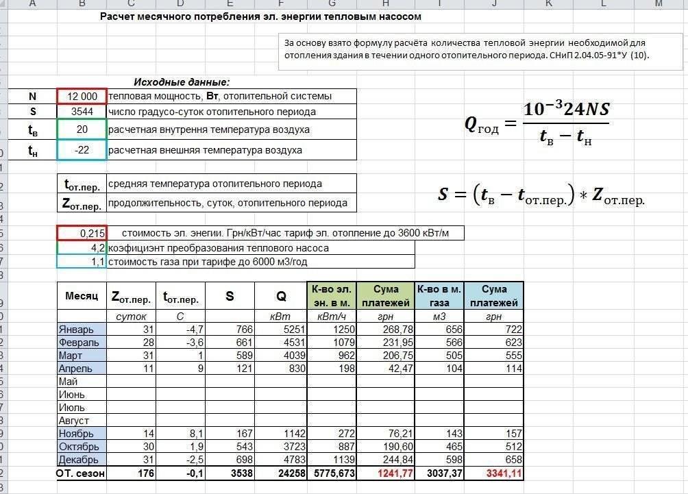
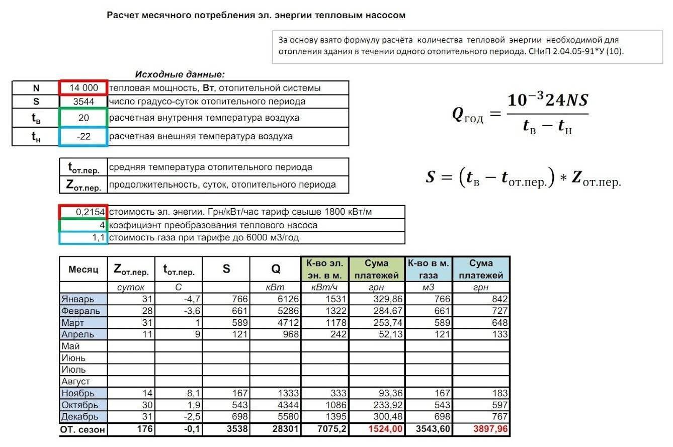
Calculation of the power of the heating boiler
The boiler as part of the heating system is designed to compensate for the heat loss of the building. And also, in the case of a double-circuit system or when the boiler is equipped with an indirect heating boiler, for heating water for hygienic needs.
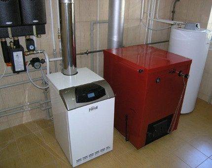
A single-circuit boiler only heats the coolant for the heating system
To determine the power of the heating boiler, it is necessary to calculate the cost of thermal energy of the house through the facade walls and for heating the replaceable air atmosphere of the interior.
Data on heat losses in kilowatt-hours per day are required - in the case of a conventional house calculated as an example, these are:
271.512 + 45.76 = 317.272 kWh,
Where: 271.512 - daily heat loss by external walls; 45.76 - daily heat loss for supply air heating.
Accordingly, the required heating power of the boiler will be:
317.272 : 24 (hours) = 13.22 kW
However, such a boiler will be under constantly high load, reducing its service life. And on especially frosty days, the design capacity of the boiler will not be enough, because with a high temperature difference between the room and outdoor atmospheres, the heat loss of the building will increase sharply.
Therefore, it is not worth choosing a boiler according to the average calculation of the cost of thermal energy - it may not be able to cope with severe frosts.
It would be rational to increase the required power of boiler equipment by 20%:
13.22 0.2 + 13.22 = 15.86 kW
To calculate the required power of the second circuit of the boiler, which heats water for washing dishes, bathing, etc., it is necessary to divide the monthly heat consumption of “sewer” heat losses by the number of days in a month and by 24 hours:
493.82: 30: 24 = 0.68 kW
According to the results of calculations, the optimal boiler power for an example cottage is 15.86 kW for the heating circuit and 0.68 kW for the heating circuit.
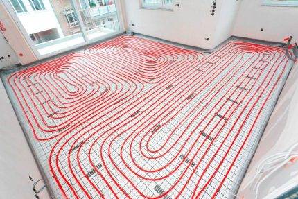
Initial data for calculation
Initially, a properly planned course of design and installation work will save you from surprises and unpleasant problems in the future.
When calculating a warm floor, it is necessary to proceed from the following data:
- wall material and features of their design;
- the size of the room in terms of;
- type of finish;
- designs of doors, windows and their placement;
- arrangement of structural elements in the plan.
To perform a competent design, it is necessary to take into account the established temperature regime and the possibility of its adjustment.
For a rough calculation, it is assumed that 1 m2 of the heating system must compensate for heat losses of 1 kW. If the water heating circuit is used as an addition to the main system, then it must cover only part of the heat loss
There are recommendations on the temperature near the floor, which ensures a comfortable stay in rooms for various purposes:
- 29°C - residential area;
- 33 ° C - bath, rooms with a pool and others with a high humidity index;
- 35°С - cold zones (at the entrance doors, external walls, etc.).
Exceeding these values entails overheating of both the system itself and the finish coating, followed by inevitable damage to the material.
After preliminary calculations, you can choose the optimal temperature of the coolant according to your personal feelings, determine the load on the heating circuit and purchase pumping equipment that perfectly copes with stimulating the movement of the coolant. It is selected with a margin of 20% for the coolant flow rate.

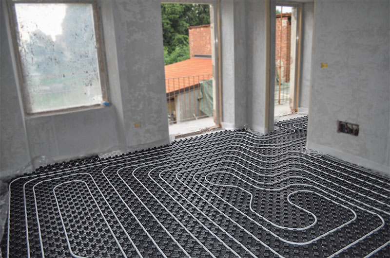
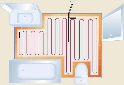
It takes a lot of time to warm up the screed with a capacity of more than 7 cm. Therefore, when installing water systems, they try not to exceed the specified limit. The most suitable coating for water floors is considered to be floor ceramics; under parquet, due to its ultra-low thermal conductivity, warm floors are not laid
At the design stage, it should be decided whether the underfloor heating will be the main heat supplier or will be used only as an addition to the radiator heating branch. The share of thermal energy losses that he has to compensate depends on this. It can range from 30% to 60% with variations.
The heating time of the water floor depends on the thickness of the elements included in the screed. Water as a heat carrier is very effective, but the system itself is difficult to install.