- What is required for the calculation
- Program snail for underfloor heating free download
- Make a request:
- Methods for laying underfloor heating pipes
- Advantages and disadvantages of underfloor heating as the main heating
- The device of a water heated floor in the house
- Minimum distance between welds
- Minimum distance between pipeline welds
- Conclusion
- A specific example of calculating a heating branch
- Step 1 - calculation of heat losses through structural elements
- Step 2 - heat for heating + total heat loss
- Step 3 - the required power of the thermal circuit
- Step 4 - determining the laying step and the length of the contour
- Varieties of pipes
- Benefits of infrared underfloor heating
- Features of electric floor systems
- Data for calculating the length of the pipeline
- Pipe length for circuit
- Underfloor heating step
- Online calculator for calculation
What is required for the calculation
In order for the house to be warm, the heating system must compensate for all heat losses through the building envelope, windows and doors, and the ventilation system. Therefore, the main parameters that will be required for calculations are:
- the size of the house;
- wall and ceiling materials;
- dimensions, number and design of windows and doors;
- ventilation power (air exchange volume), etc.
You also need to take into account the climate in the region (minimum winter temperature) and the desired air temperature in each room.
These data will allow you to calculate the required thermal power of the system, which is the main parameter for determining the pump power, coolant temperature, pipe length and cross section, etc.
The calculator posted on the websites of many construction companies that provide services for its installation will help to perform a heat engineering calculation of a pipe for a warm floor.
Screenshot from calculator page
Program snail for underfloor heating free download
Underfloor heating project
Professional design of underfloor heating systems (water floor heating) for buildings of various purposes and designs (cottage, shopping center, business center, service station, workshop, etc.), and any heat sources in accordance with European and Russian standards and norms.
The project is necessary for the installation of a water heated floor and is a system passport, incl. for future system maintenance.
The project includes the calculation of heat loss of the building, taking into account the climatic zone. Materials, thickness and construction of walls, ceilings, insulation of the foundation and roof, filling of door and window openings, floor plans are taken into account. When designing, all the features of the building and individual wishes of customers are taken into account. The completed project of underfloor heating system includes the following main sections:
- results of thermal engineering calculation,
- system passport,
- wiring diagrams for laying underfloor heating pipes, mains, damper tape, thermostat arrangement,
- balancing tables for underfloor heating collectors,
- specification of materials and components.
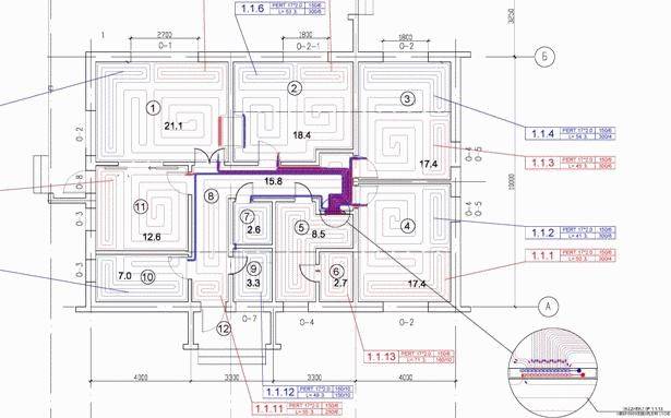
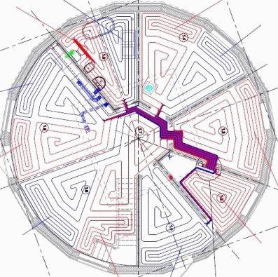
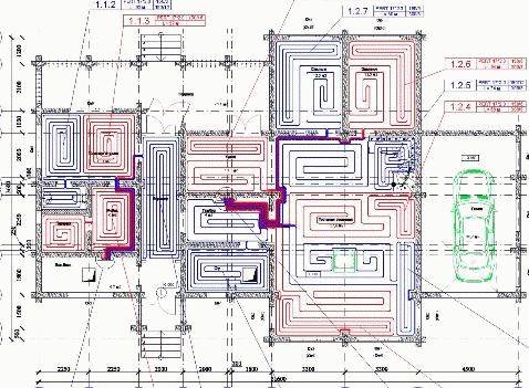
In our projects, pipe laying is carried out by an experienced designer, and the pipes are laid in accordance with the Thermotech "meander" ("snail") method and with variable pitch with the allocation of edge (weld) zones. Unlike some firms working under the "umbrella" of famous brands, where the layout of pipes is automatically performed by a "proprietary" computer program that uses a primitive "snake" with the same pitch. In warm Europe, the “snake” is used for buildings with very low heat losses (up to 30 W / m2), with increased heat losses, designers are forced to switch to the “snail” and use welt zones along the outer walls to compensate for increased heat losses. Programs don't do that yet.
But, as a rule, in our climatic conditions, and with the lagging standards for insulation of enclosing structures, as well as the massively practiced lack of external thermal insulation in individual construction, everything is much worse with heat losses. It is good if the heat loss of the house is within the value of 75-80 W / m2 of the floor, but more is also not uncommon, but rather the opposite in private buildings. But our specialists have long and successfully been engaged in the design and implementation of underfloor heating systems in the harsh conditions of Siberia and have tremendous experience in this area. This allows us to carry out projects that best suit our (and any) climatic conditions and the individual characteristics of a particular facility.
To develop a project for a water-heated floor, ideally, you need a building project or, at least, floor plans, preferably in AutoCad format. In their absence, floor plans with all dimensions drawn by hand are needed.In addition, the terms of reference for the design are drawn up and agreed upon.
The design of the floor heating system is carried out taking into account the characteristics of the building and the wishes of the customer. For weak ceilings or thin systems, lightweight underfloor heating systems with aluminum heat distribution plates or a foil system can be used in the project.
The result of the design is a package of technical documentation containing a system passport with the result of thermal calculations, wiring diagrams for laying pipes for underfloor heating and arranging room thermostats, balancing tables for collectors and a specification of materials, equipment and components.
The completed project allows you to fully equip the system with equipment, components and materials in accordance with the attached specification and to install and commission a workable system.
Tags: floor scheme, floor calculation, warm floor scheme, warm floor calculation, warm floor calculation, water floor scheme, water heated floor scheme, water floor calculation, warm floor water calculation,
Use the online chat on the site in the lower right corner of the page
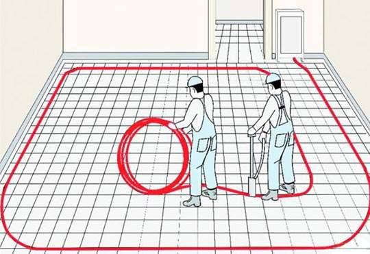
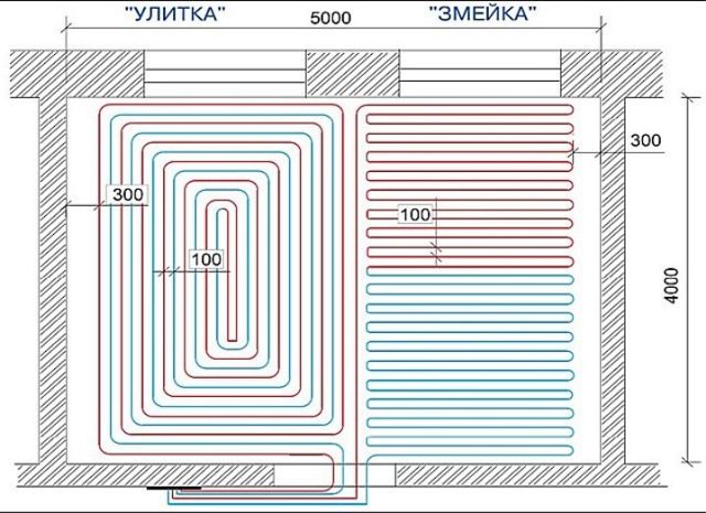
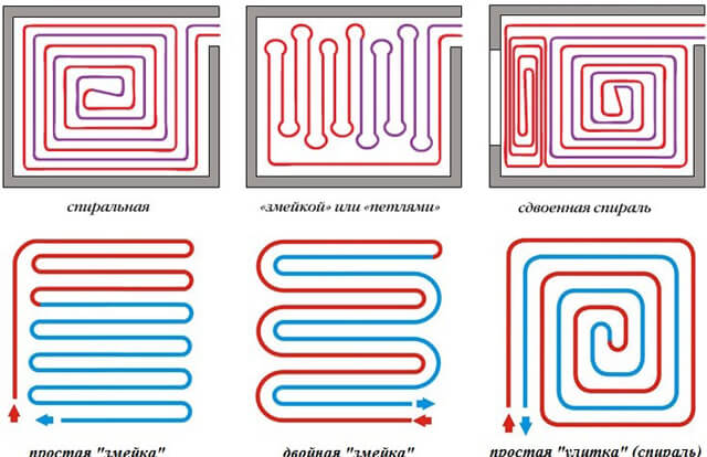
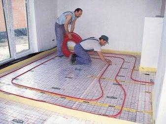
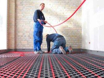
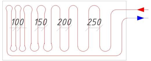
Methods for laying underfloor heating pipes
The choice of pipe laying scheme is equated to the shape of the room (room). Coil configurations can be divided into two main types of piping: parallel. and spiral. Parallel laying: in this type of laying, the floor temperature varies greatly - the highest will be at the beginning of the coil and correspondingly lower at the end. Typically, this scheme is used in small rooms (for example, in bathrooms).With this scheme, the hottest pipe, that is, the place where the coolant enters the coil, should be located in the coldest zone of the room (for example, at the outer wall) or in the zone of greatest comfort (for example, in bathrooms without external walls). This scheme makes it possible to lay pipes on floors with a slope (for example, towards a floor drain). Spiral laying: in this type of laying, the floor temperature remains constant throughout the room - opposite flow directions alternate, with the hottest section of the pipe adjacent to the coldest. The use of this scheme is recommended in places where the temperature difference is undesirable and, of course, in large rooms (halls). This scheme is not suitable for laying on sloping floors.
Any combination of basic types of laying is possible. In colder zones (near the outer walls), it is recommended to take a smaller layout step (distance between pipes) or to break the pipe layout into separate zones of the room - colder and warmer. The coldest area in the room will always be the area along the outer wall and it is in this area that the hottest pipes should be located.
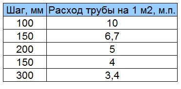
The pipe layout step (B) is taken taking into account the minimum bending radius of the pipes (it is larger for polyethylene pipes). Usually, B \u003d 50, 100, 150, 200, 250, 300 and 350 mm are selected. The approximate length of the coil pipes per 1 sq.m. floor area can be calculated using the following formula: L=1000/B(mm/m2). The total length of the pipes (rm) is equal to L / 1000 x F (heated floor area m2). Special brackets are used to fasten the pipes, with an approximate distance between them of 0.4-0.5 m.


Advantages and disadvantages of underfloor heating as the main heating
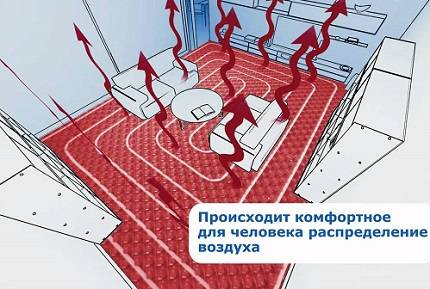
The main advantage is comfort. The warm floor under your feet creates a feeling of warmth and comfort much faster than the hot air of the room. There are other benefits too:
- Uniform heating of the room. Heat comes from the entire floor area, while the batteries partially warm the walls and distribute heat only in a certain area.
- The system is completely silent.
- Since the heating elements are enclosed in a screed, heating has less effect on the humidity level.
- You can choose an option with different thermal inertia. The water floor slowly heats up and cools down for almost a day. IR film instantly heats the floor surface and cools just as quickly.
- Heating with a water-heated floor is cheaper than radiators. The cost of electric heating is not so attractive.
- They mount systems on the smallest platforms, even on stairs.
- Batteries do not decorate the room and do not fit into the interior. Heating elements of a heat-insulated floor are hidden from eyes.
Flaws:
- Arranging a warm floor is a laborious and lengthy process. Hydro and thermal insulation is laid on the base base. Then place the reinforcing mesh or laying mats. The tubes are placed, the connection is made, the concrete screed is poured, the substrate is laid and the finishing floor is laid. This takes time and money.
- Water floor heating takes at least 10 cm of height, and electric - from 3 to 5 cm.
- Repair is very difficult: in case of damage, it is necessary to remove the coating, break the screed, eliminate defects and re-lay the floor.
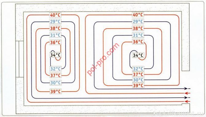
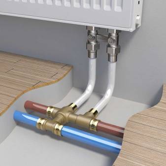
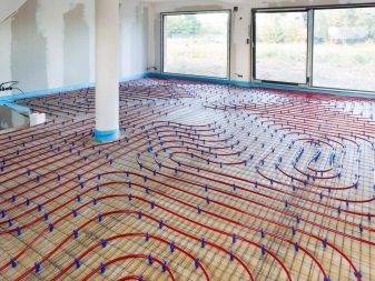
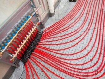
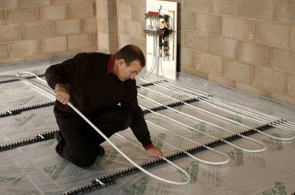
The device of a water heated floor in the house
The heat carrier in the floor is mounted in the form of a single or double snake, spiral. The total length of the pipe depends on the choice of the location of the contour.The ideal option is the coils of the same size. However, in practice, creating uniform loops is difficult and impractical.
When the floor is made throughout the house, the parameters of the premises are taken into account. In the bathroom, bathroom, hallway, which occupy a smaller area compared to the living room, bedroom or other rooms, it is difficult to create long coils. They do not require many pipes to heat them. Their length can be limited to a few meters.
Some zealous owners, when arranging a water circuit, bypass these premises. This saves materials, labor and time. In small rooms, it is more difficult to install a warm floor than in spacious ones.
If the system bypasses such cubbyholes, it is important to correctly calculate the maximum pressure parameters in the system. To do this, use a balancing valve. It is designed to equalize the pressure loss in different circuits.
It is designed to equalize the pressure loss in different circuits.
Minimum distance between welds
The distance between welds in metal structures is determined under different conditions. Below are the main examples with distance restrictions.
| Type of seams and objects near which they are located | Determining the minimum distance |
| The distance between the axes of the seams, which are adjacent, but do not mate with each other. | Not less than the nominal thickness of the parts to be welded. If the wall is more than 8 mm, then the distance should be from 10 cm and above. With the minimum dimensions of the workpiece, the distance should be at least 5 cm. |
| The distance from the rounding of the bottom of the workpiece to the axis of the butt weld. | It does not take into account the exact dimensions, but the possibility of subsequently conducting control using ultrasound. |
| Welded joints in boilers. | When located in boilers, welds should not reach the supports and come into contact with them. There are also no exact data here, but the distance should allow you to monitor the state of the boiler during operation and not interfere with quality control. |
| Distance from holes to weld. | This includes holes for welding or flaring. This distance should not exceed 0.9 of the diameter of the hole itself. |
| Distance from weld to tie-in. | Here, on average, a distance of about 5 cm is left. If we are talking about large diameters, then it can change upwards. |
| The distance between adjacent seams at the holes. | The minimum distance should be from 1.4 diameters. |
There are rules that allow you to place the seams at a shorter distance, which will be less than 0.9 of the diameter of the hole itself. This applies to those cases when it is planned to weld fittings and pipes. There are certain conditions for all this. For example, before drilling holes, welded joints must be subjected to radiographic analysis. Ultrasonic testing can also be used instead. The calculation of the allowance will be carried out at a distance of at least one square root of the diameter. It is necessary to make a preliminary calculation, which should show whether the product meets the specified strength parameters.
Minimum distance between pipeline welds
The minimum distance between the welds of the heating network pipeline is also regulated by certain documents. Taking into account the fact that the repair of pipes and the installation of pipelines by welding is more often carried out by specialists who work with critical structures, compliance with the standards is more relevant here.
| Type of seams and objects near which they are located | Determining the minimum distance |
| Welding near transverse spiral, circumferential and longitudinal seams of any elements, with the exception of cathode leads. | Here you need to follow the rules very strictly, since this is strictly prohibited. Only if there are cathode leads provided for by the projects, the minimum distance between the seams should be at least 10 cm. |
| Distance between process pipeline welds. | It is calculated according to the wall thickness of the pipe itself. The minimum distance between seams for pipes with a wall thickness of up to 3 mm is 3 times the pipe wall thickness. If its size is above 3 mm, then a distance of two pipe wall thicknesses between the seams is allowed. |
| Seam distance from pipe bend. | If you have to work with a pipe that has a bend, then the distance from the seam to the bend should be at least half the diameter of the pipe itself. |
The calculations of the pipeline itself are carried out in advance so that all bends, additional connections and other nuances of the structures comply with the accepted rules. During repairs, errors are often made and the rules are not always followed, but this does not guarantee that the seam made will last a long time. After all, all tolerances for the distances between the seams are taken on the basis of the experience of previous work. The minimum distance between the welds of the pipeline is determined in accordance with GOST 32569-2013. All data regarding the operation, installation and repair of technological pipelines are indicated here.
Conclusion
The relevance of observing distances most of all concerns critical structures that are carried out using certain technologies.Most people who only weld at home may not even have heard of such restrictions. For professionals working with a specific technical task, where all the rules must be strictly observed, the calculation of the minimum distance is mandatory.
A specific example of calculating a heating branch
Suppose you want to determine the parameters of the thermal circuit for a house with an area of 60 square meters.
For the calculation, the following data and characteristics will be needed:
- dimensions of the room: height - 2.7 m, length and width - 10 and 6 m, respectively;
- in the house there are 5 metal-plastic windows of 2 sq. m;
- external walls - aerated concrete, thickness - 50 cm, Kt \u003d 0.20 W / mK;
- additional wall insulation - polystyrene foam 5 cm, Kt \u003d 0.041 W / mK;
- ceiling material - reinforced concrete slab, thickness - 20 cm, Kt = 1.69 W / mK;
- attic insulation - polystyrene foam plates 5 cm thick;
- dimensions of the entrance door - 0.9 * 2.05 m, thermal insulation - polyurethane foam, layer - 10 cm, Kt = 0.035 W / mK.
Let's take a look at the step by step calculation example.
Step 1 - calculation of heat losses through structural elements
Thermal resistance of wall materials:
- aerated concrete: R1=0.5/0.20=2.5 sq.m*K/W;
- expanded polystyrene: R2=0.05/0.041=1.22 sqm*K/W.
The thermal resistance of the wall as a whole is: 2.5 + 1.22 = 3.57 sq. m*K/W. We take the average temperature in the house as +23 ° C, the minimum outside is 25 ° C with a minus sign. The difference in indicators is 48 ° C.


Calculation of the total area of the wall: S1=2.7*10*2+2.7*6*2=86.4 sq. m. It is necessary to subtract the value of windows and doors from the obtained indicator: S2 \u003d 86.4-10-1.85 \u003d 74.55 square meters. m.
Substituting the obtained indicators into the formula, we get wall heat losses: Qc = 74.55 / 3.57 * 48 = 1002 W
By analogy, heat costs are calculated through windows, doors and ceilings. To assess energy losses through the attic, the thermal conductivity of the floor material and insulation is taken into account
The final thermal resistance of the ceiling is: 0.2 / 1.69 + 0.05 / 0.041 \u003d 0.118 + 1.22 \u003d 1.338 square meters. m*K/W. Heat losses will be: Qp=60/1.338*48=2152 W.
To calculate the heat leakage through the windows, it is necessary to determine the weighted average value of the thermal resistance of materials: a double-glazed window - 0.5 and a profile - 0.56 sq. m * K / W, respectively.
Ro \u003d 0.56 * 0.1 + 0.5 * 0.9 \u003d 0.56 sq.m * K / W. Here 0.1 and 0.9 are the share of each material in the window structure.
Window heat loss: Qо=10/0.56*48=857 W.
Taking into account the thermal insulation of the door, its thermal resistance will be: Rd \u003d 0.1 / 0.035 \u003d 2.86 square meters. m*K/W. Qd \u003d (0.9 * 2.05) / 2.86 * 48 \u003d 31 W.
The total heat loss through the enclosing elements is: 1002+2152+857+31=4042 W. The result must be increased by 10%: 4042 * 1.1 = 4446 W.
Step 2 - heat for heating + total heat loss
First, we calculate the heat consumption for heating the incoming air. Room volume: 2.7 * 10 * 6 \u003d 162 cubic meters. m. Accordingly, the ventilation heat loss will be: (162*1/3600)*1005*1.19*48=2583 W.
According to the parameters of the room, the total heat costs will be: Q=4446+2583=7029 W.
Step 3 - the required power of the thermal circuit
We calculate the optimal circuit power required to compensate for heat losses: N=1.2*7029=8435 W.
Further: q=N/S=8435/60=141 W/sq.m.
Based on the required performance of the heating system and the active area of \u200b\u200bthe room, it is possible to determine the heat flux density per 1 sq. m
Step 4 - determining the laying step and the length of the contour
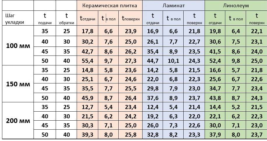
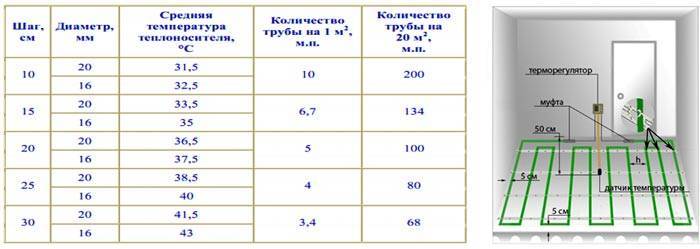
The resulting value is compared with the dependency graph.If the temperature of the coolant in the system is 40 ° C, then a circuit with parameters is suitable: pitch - 100 mm, diameter - 20 mm.
If water heated to 50 ° C circulates in the line, then the interval between branches can be increased to 15 cm and a pipe with a cross section of 16 mm can be used.
We consider the length of the contour: L \u003d 60 / 0.15 * 1.1 \u003d 440 m.
Separately, it is necessary to take into account the distance from the collectors to the heating system.
As can be seen from the calculations, at least four heating loops will have to be made to equip the water floor. And how to properly lay and fix the pipes, as well as other installation secrets, we examined here.


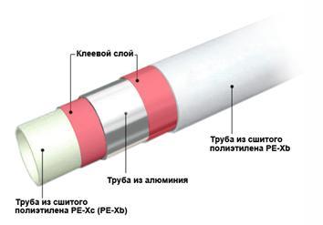
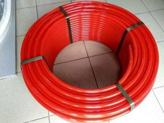
Varieties of pipes
The floor is a connection of pipes connected to the collector. Correct data measurements are the basis for calculating the power of thermal equipment. To calculate the distance between the pipes and the length required for laying, it is worth familiarizing yourself with the main types of structures and their features. For the installation of a warm water floor, pipes made of the following materials are used:
- Cross-linked polyethylene. This material is difficult to install and has a rather high cost. However, it also has a lot of advantages, for example, it has the property of memory, does not corrode, and is resistant to temperature changes.
- Copper. One of the most resistant materials, characterized by high strength, resistance to corrosion. The downside is that copper is quite expensive, such pipes are difficult to install.
- Metal-plastic. The advantages of the material are its economy, strength and safety, from the point of view of ecology.
- Polypropylene. Polypropylene pipes are characterized by low cost with high technological characteristics, including low thermal conductivity.
To calculate the required number of pipes, it is necessary to take into account the laying features that will make the operation as efficient as possible:
- the average pipe diameter is 16 mm, and the thickness of the screed is 6 cm;
- the average laying step in the contour spiral is 10–15 cm;
- the length of the pipe in the heating circuit should not exceed 100 meters, while it should be borne in mind that the pipe must exit and enter the collector without breaks;
- the distance between the pipe and the wall should remain between 8 and 25 cm;
- the total length of the circuit should be 100 meters with a total area of 20 m2;
- between the lengths of the turns it is worth observing the difference not exceeding 15 meters;
- the minimum allowable pressure inside the collector is 20 kPa;
- the shorter the pipeline, the less the need to install a powerful pump, as the level of pressure drop is reduced;
- the temperature of the heat carrier at the inlet should not differ from the outlet temperature by more than 5 degrees.

Benefits of infrared underfloor heating
Modern designs of infrared floor have a number of undeniable advantages. First of all, they are distinguished by simplicity and speed of installation. Installation of floors, on average, takes no more than two hours. They do not require a tie-down device. These floors are easy to install under carpet, linoleum or laminate. The thickness of the film is only 3 mm, therefore, it does not affect the height of the room at all and does not reduce its volume. The film coating material is highly reliable.
Compared to other types of underfloor heating, infrared construction allows significant energy savings. In addition, there are many positive physical properties.Infrared floors help to ionize the air and eliminate various unpleasant odors. They absolutely do not affect the humidity of the air and do not dry it.
This type of underfloor heating can be used as the main or additional source of heating for houses and apartments. In the first case, film coverage is at least 60-70% of the total area of the room. With additional heating, any area is covered, on average, this value is 30-50%. Infrared floors are installed in walk-through corridors throughout the area, provided there is no furniture. In rooms with furniture, the film is installed as needed, in free places.
Features of electric floor systems
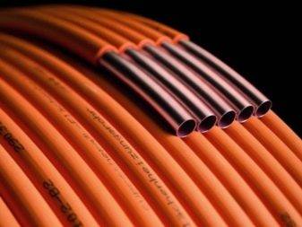
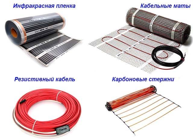
The technology for preparing and laying out electric heating elements differs from the design of water circuits and depends on the type of heating elements selected:
- resistive cables, carbon rods and cable mats can be laid “dry” (directly under the coating) and “wet” (under the screed or tile adhesive);
- the carbon infrared films shown in the photo are best used as a substrate under a coating without pouring a screed, although some manufacturers allow laying under a tile.
Electric heating elements have 3 features:
- uniform heat transfer along the entire length;
- the intensity of heating and the surface temperature is controlled by a thermostat, guided by the readings of the sensors;
- intolerance to overheating.
The last property is the most annoying. If on the contour section the floors are forced with furniture without legs or stationary household appliances, heat exchange with the surrounding air will be disturbed. Cable and film systems will overheat and will not last long.All the nuances of this problem are covered in the next video:
Self-regulating rods calmly endure such things, but another factor begins to influence here - it is irrational to buy and lay expensive carbon heaters under furniture.
Data for calculating the length of the pipeline
In order to calculate the length of pipelines for a certain space of the room, the following data will be needed: the diameter of the coolant, the step of laying the floor heating pipe, the heated surface.
Pipe length for circuit
The length of the coolant directly depends on the outer diameter of the pipe. Therefore, if you miss this moment of calculation at the initial stage, there will be difficulties with the circulation of water, which in turn will lead to poor-quality floor heating. It is possible to consider the permissible cross-sectional norms of the underfloor heating pipe and its length according to the following scheme.


| Outside pipe diameter | Maximum pipe size |
| 1.6 - 1.7 cm. | 100 - 102 m. |
| 1.8 - 1.9 cm. | 120 - 122m. |
| 2 cm | 120 - 125 m. |
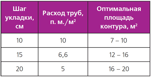
But since the circuit must be made of solid material, the number of circuits for the heating area will be affected by the step of laying the water-heated floor.
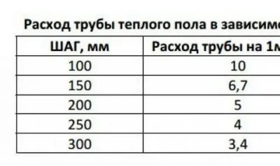
Underfloor heating step
Not only the length of the pipeline, but also the heat transfer power will depend on the laying step. Therefore, with the correct installation of heat carriers, it will be possible to save on the energy consumption of underfloor heating.
The recommended step for laying underfloor heating pipes is considered to be 20 cm. This indicator is due to the fact that when it is used, the floor is evenly heated, and installation work is also simplified. In addition to this indicator, the following norms are also allowed: 10 cm. 15 cm. 25 cm. and 30 cm.
Let's give a good example, the flow rate of the pipeline at the optimal step of the warm floor.
| step, see | Consumption of working material per 1 sq.m., m. |
| 10 — 12 | 10 – 10,5 |
| 15 — 18 | 6,7 – 7,2 |
| 20 — 22 | 5 – 6,1 |
| 25 — 27 | 4 – 4,8 |
| 30 — 35 | 3,4 – 3,9 |
With a denser laying, the turns of the product will be loop-shaped, which will complicate the circulation of the coolant. And with a larger installation step, the heating of the room will not be uniform.
Online calculator for calculation
Since the contour of the warm floor should capture the total area of \u200b\u200bthe room as much as possible, it is necessary to draw up a diagram of its location. To do this, you need a millimeter sheet of paper and a pencil. The scheme is drawn up in the following order:
- On paper, the total area of \u200b\u200bthe room is drawn.
- The dimensions of overall furniture and floor electrical equipment are measured.
- In the appropriate arrangement, all measurements are transferred to paper.
- It is strictly forbidden for the coolant to pass close to the walls, therefore, an indent of 20 cm is made along the entire drawn area.
By shading all the applied measurements and indents, you can visually calculate the area of \u200b\u200bthe room where the coolants will be located.
So, knowing all the necessary data, you can proceed to the direct calculation of the working material of the heating system.
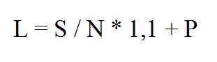
The length is calculated using the following formula:
D = P/T ˟ k, where:
D - pipe length;
P is the heated area of the room;
T - pipe pitch for a warm water floor;
k is the reserve indicator, which is in the range of 1.1-1.4.