
- How to draw up a plan for laying the floor according to the plan?
- Scheme for a two-story house
- Multi-room premises (house, apartment)
- Scheme for a room with a complex bending of the walls
- What you should pay attention to when designing a water heated floor in an apartment with a central heating system
- Features of electric floor systems
- Screed
- Why is it better to use a pipe with an outer diameter of 16 mm?
- We determine the power and the list of materials
- How to calculate heat loss
- Warm floor power calculation
- System load
- Calculation of heat transfer power: calculator
- Calculations
- Selection of pipes and manifold assembly
- Design principles
- Ways to adjust contours
- insulation
- Collector-mixing unit
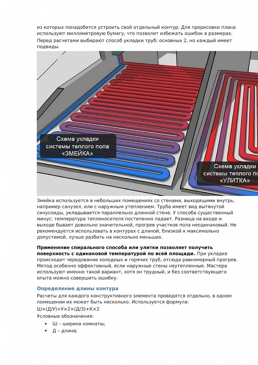
- Possible ways of laying the contour
- Method #1 - snake
- Method # 2 - snail or spiral
- Final part
- Calculation of the power of the water floor
- Parameters for the water floor
- Power calculation methodology
- Calculation taking into account furniture
- Conclusions and useful video on the topic
How to draw up a plan for laying the floor according to the plan?
The scheme is created even before you have purchased all the materials. It helps not only to properly install a warm floor, but also to plan the volume of purchased materials.
First, draw a room in which laying is planned. It can be 1 room, the whole apartment or the whole house (private).Make the drawing correctly, in accordance with the size of your room. The scheme "by eye" will not give any accuracy. Take into account the square meters of the room and transfer to paper or the workspace of the software on a PC.
In this video you can get acquainted with the PC program for designing a floor plan. Video review, the possibilities of the program are presented, a brief instruction on how to work with it.
What is included in the plan:
- building plan (taking into account all floors);
- material of the floor, walls, windows and doors;
- the desired temperature in the heated room;
- location of collectors and heating boiler;
- detailed arrangement of furniture, its dimensions, taking into account sq. meters of the room;
- average ambient temperature in winter;
- the presence of another source of heat (battery, fireplace, split system, etc.)
Tips and tricks during the schema creation phase:
- The approximate area for 1 circuit should be more than 15 square meters. m.
- In large rooms, install several circuits. They should not differ in length by more than 15 m.
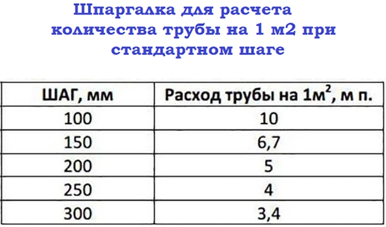
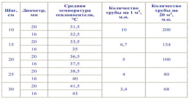
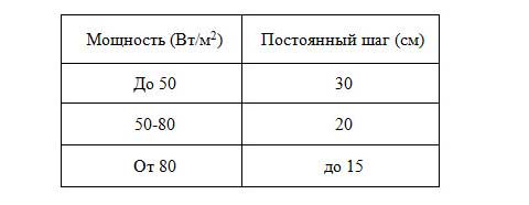
- If the step is 15 cm, it will be equal to the pipe flow rate of 6.7 m per 1 sq. m. If the installation is every 10 cm, then the flow will mean per 1 sq. m - 10 meters.
- The minimum bending radius of a pipe is equal to 5 of its diameters.
- Considering that heated water will first pass through the pipes, and then it will gradually cool down and return to the collector already cooled down, laying should begin in those places that are most susceptible to cooling (windows, corner walls).
- The scheme plan can be applied manually - on graph paper.
In the video, the master manually draws a scheme for installing a warm floor on paper. Gives illustrative examples of calculation.
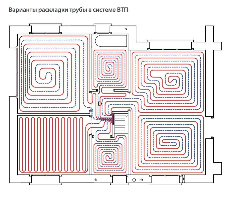
When drawing up the diagram, please note that the collector is installed in the center of the room (see.diagram below)
It is important that the distance of all contours is approximately the same.
What is the best styling option? Preference should be given to the scheme that best suits a particular room. This has already been said above.
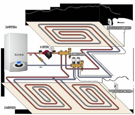
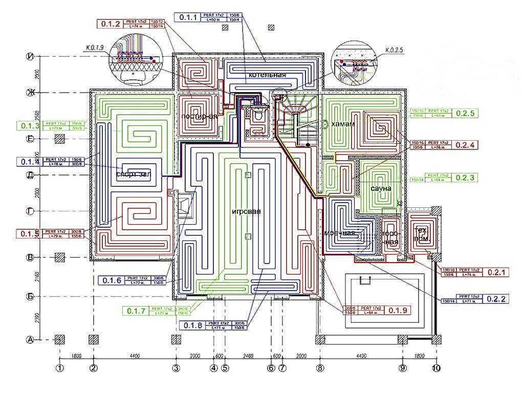
Scheme for a two-story house
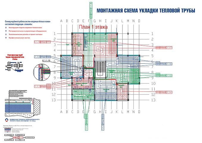
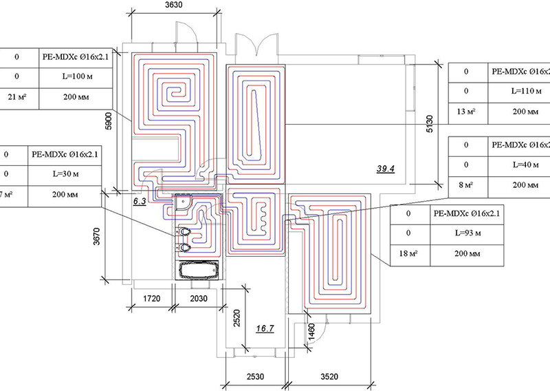
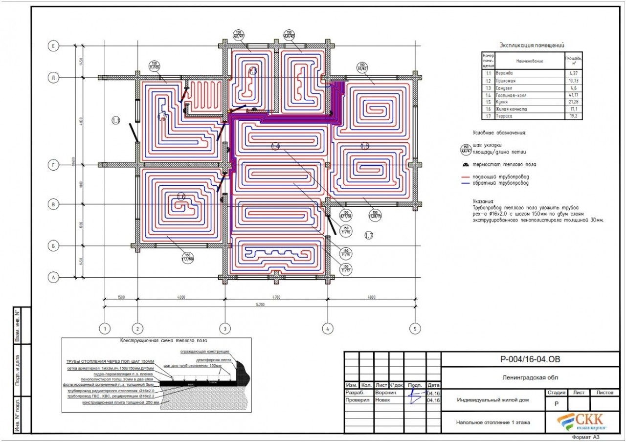
The plan below shows a layout of underfloor heating on 2 floors. The first floor has a large area, so a double-circuit heating system "Snail" is used.
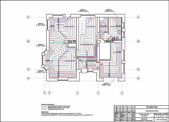
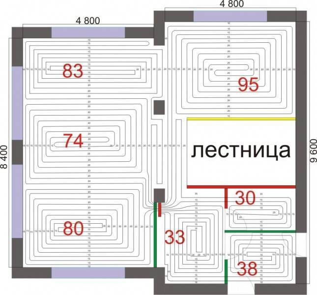
Multi-room premises (house, apartment)
The plan shows that the "Snail" is used throughout the room. This also applies to the bathroom and kitchen.
Please note that the contours do not pass under furniture, appliances and plumbing
Scheme for a room with a complex bending of the walls
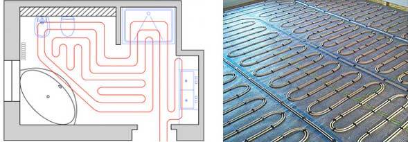
When laying the floor, you may encounter a little difficulty - the curves of the walls, unique, designer layouts. In such cases, it is not easy to install an even snake or snail. A combined stacking system is used.
The coolant is laid based on the shape and bending of the walls. See the figure below for how you can plan a pipe laying scheme. The interior space is also taken into account.
What you should pay attention to when designing a water heated floor in an apartment with a central heating system
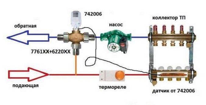
The correct solution would be to use a heat exchanger. You pass the central heating coolant through the primary circuit, take the required heat and transfer it to the secondary circuit of underfloor heating.
Why exactly? Because in the central heating system, the coolant pressure sometimes reaches 16 atmospheres, which is not typical for many nodes and mechanisms for underfloor heating, which are designed for operating pressures from 1 to 2.5 atmospheres.
The best thing of course (from my personal experience, maybe someone will disagree with this, but) is to take the coolant for underfloor heating from the line going to the dryer towel, as a rule, this branch is not too loaded and is located inside the building without giving off heat to the outer walls, thus, it is usually the warmest in the apartment, and the diameters of the pipes are good).
But there are exceptions, sometimes a towel dryer is powered from a central hot water supply. There's nothing to be done, you have to take the coolant from the radiator line. There are still twofold opinions on this issue with radiators, where to get the coolant from the "supply" or "return"? It seems that the temperature of the return line of the central heating to the warm floor is enough, but at the beginning and end of the heating season it may not be enough, here you can think about this.


Features of electric floor systems
The technology for preparing and laying out electric heating elements differs from the design of water circuits and depends on the type of heating elements selected:
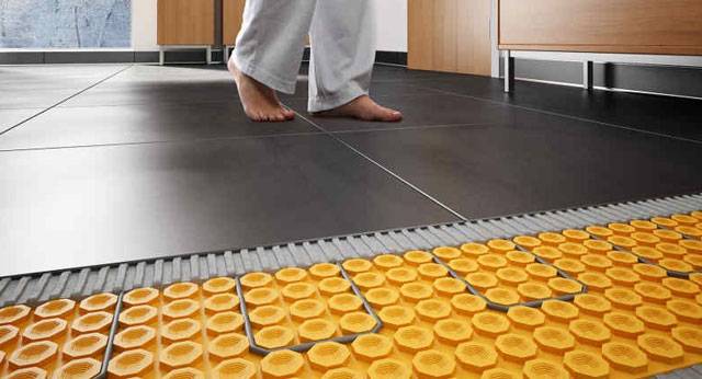
- resistive cables, carbon rods and cable mats can be laid “dry” (directly under the coating) and “wet” (under the screed or tile adhesive);
- the carbon infrared films shown in the photo are best used as a substrate under a coating without pouring a screed, although some manufacturers allow laying under a tile.
Electric heating elements have 3 features:
- uniform heat transfer along the entire length;
- the intensity of heating and the surface temperature is controlled by a thermostat, guided by the readings of the sensors;
- intolerance to overheating.
The last property is the most annoying.If on the contour section the floors are forced with furniture without legs or stationary household appliances, heat exchange with the surrounding air will be disturbed. Cable and film systems will overheat and will not last long. All the nuances of this problem are covered in the next video:
Self-regulating rods calmly endure such things, but another factor begins to influence here - it is irrational to buy and lay expensive carbon heaters under furniture.
Screed
IMPORTANT: the top layer of the screed is poured only when the contour is filled. But before that, metal pipes are grounded and covered with a thick plastic film.
This is an important condition to prevent corrosion due to electrochemical interactions of materials.
The issue of reinforcement can be solved in two ways. The first is to put a masonry mesh on top of the pipe. But with this option, cracks may appear due to shrinkage.
Another way is dispersed fiber reinforcement. When pouring water heated floors, steel fiber is best suited. Added in the amount of 1 kg/m3 of solution, it will be evenly distributed throughout the volume and qualitatively increase the strength of the hardened concrete. Polypropylene fiber is much less suitable for the top layer of the screed, because the strength characteristics of steel and polypropylene do not even compete with each other.
Beacons are installed and the solution is kneaded according to the above recipe. The thickness of the screed must be at least 4 cm above the surface of the pipe. Considering that the ø of the pipe is 16 mm, the total thickness will reach 6 cm. The maturation time of such a layer of cement screed is 1.5 months
IMPORTANT: It is unacceptable to speed up the process including floor heating! This is a complex chemical reaction of the formation of "cement stone", which occurs in the presence of water. Heat will cause it to evaporate
You can accelerate the maturation of the screed by including special additives in the recipe. Some of them cause complete hydration of the cement after 7 days. And besides this, shrinkage is significantly reduced.
You can determine the readiness of the screed by placing a roll of toilet paper on the surface and covering it with a saucepan. If the ripening process is over, then in the morning the paper will be dry.
Why is it better to use a pipe with an outer diameter of 16 mm?
To begin with, why is a 16 mm pipe being considered?
Everything is very simple - practice shows that for "warm floors" in a house or apartment of this diameter is enough. That is, it is difficult to imagine a situation where the circuit does not cope with its task. This means that there is no really justified reason to use a larger, 20-millimeter one.
Most often, in the conditions of an ordinary residential building, pipes with a diameter of 16 mm are more than enough for "warm floors"
And, at the same time, the use of a 16 mm pipe provides a number of advantages:
- First of all, it is about a quarter cheaper than the 20mm counterpart. The same applies to all the necessary fittings - the same fittings.
- Such pipes are easier to lay, with them it is possible, if necessary, to perform a compact step of laying out the contour, up to 100 mm. With a 20 mm tube, there is much more fuss, and a small step is simply impossible.
A pipe with a diameter of 16 mm is easier to fit and allows you to maintain a minimum step between adjacent loops
- The volume of coolant in the circuit is significantly reduced.A simple calculation shows that in a linear meter of a 16 mm pipe (with a wall thickness of 2 mm, the inner channel is 12 mm) holds 113 ml of water. And in 20 mm (inner diameter 16 mm) - 201 ml. That is, the difference is more than 80 ml per just one meter of pipe. And on the scale of the heating system of the whole house - this literally translates into a very decent amount! And after all, it is necessary to ensure the heating of this volume, which entails, in principle, unjustified energy costs.
- Finally, a pipe with a larger diameter will also require an increase in the thickness of the concrete screed. Like it or not, but at least 30 mm above the surface of any pipe will have to be provided. Let these "unfortunate" 4–5 mm do not seem ridiculous. Anyone who was involved in pouring the screed knows that these millimeters turn into tens and hundreds of kilograms of additional concrete mortar - it all depends on the area. Moreover, for a 20 mm pipe, it is recommended to make the screed layer even thicker - about 70 mm above the contour, that is, it turns out to be almost twice as thick.
In addition, in residential premises very often there is a “struggle” for every millimeter of floor height - simply for reasons of insufficient “space” to increase the thickness of the overall “pie” of the heating system.
An increase in the diameter of the pipe invariably leads to a thickening of the screed. And this is not always possible, and in most cases it is completely unprofitable.
A 20 mm pipe is justified when it is necessary to implement a floor heating system in rooms with a high load, with a high intensity of people's traffic, in gyms, etc.There, simply for reasons of increasing the strength of the base, it is necessary to use more massive thick screeds, for the heating of which a large heat exchange area is also required, which is exactly what a pipe of 20, and sometimes even 25 mm, provides. In residential areas, there is no need to resort to such extremes.


It may be objected that in order to "push" the coolant through a thinner pipe, it will be necessary to increase the power indicators of the circulation pump. Theoretically, the way it is - the hydraulic resistance with a decrease in diameter, of course, increases. But as practice shows, most circulation pumps are quite capable of this task.
Below, attention will be paid to this parameter - it is also linked to the length of the contour. This is what calculations are made in order to achieve optimal, or at least acceptable, fully functional performance of the system.
So, let's focus on the pipe exactly 16 mm. We will not talk about the pipes themselves in this publication - that is a separate article of our portal.
We determine the power and the list of materials
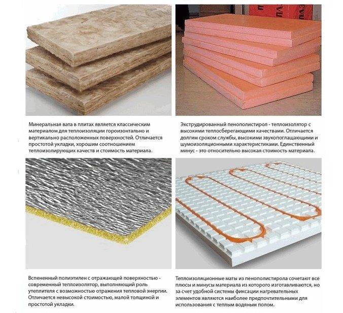
To calculate the power, several criteria must be taken into account in order to make the right choice in favor of a particular device. First of all, this is the type of the chosen room, its quadrature and the method of heating. It is worth noting that in order to calculate the area correctly, you should use only its useful part, not taking into account furniture and other interior items. As a heater, it is recommended to use extruded polystyrene foam, as it has high rates of solidity and durability.
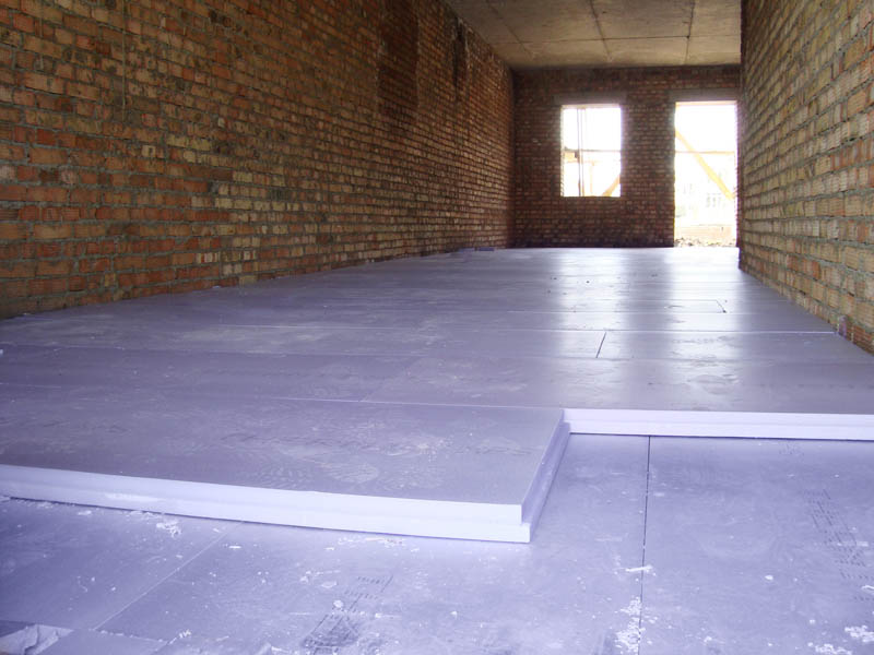
Styrofoam extruded photo
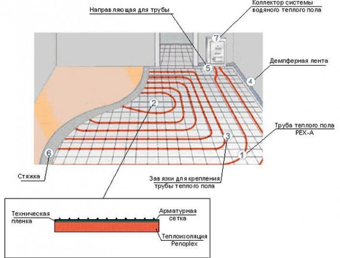
Waterproofing is laid on top of the insulation.In this case, you can use the usual polyethylene film. To fasten the sheets, you need a damper tape. Reinforcement is a kind of base, which is used to fasten the screed and pipes. You can’t do without special brackets for fixing pipes, so they are indispensable elements of the underfloor heating system. For uniform distribution of the coolant, a distributing collector is used. Plus, it will help you save a lot.
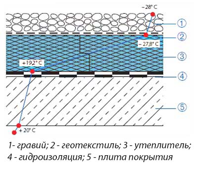
The scheme of laying waterproofing
How to calculate heat loss
From the result obtained depends on how much heat the room will need to ensure a comfortable temperature in it, and what power the floor heating system and the heating boiler with a circulation pump should have.
Calculation of heat losses is complicated, since they are influenced by many parameters and initial data:
- season;
- temperature outside the window;
- purpose of the premises;
- the size of window openings and their number;
- type of finish;
- the degree of thermal insulation of enclosing structures;
- what room is located above and below the room (heated or not);
- availability of other sources of heat.
Warm floor power calculation
The determination of the required power of a warm floor in a room is influenced by the heat loss indicator, for an accurate determination of which it will be necessary to make a complex heat engineering calculation using a special method.
- This takes into account the following factors:
- the area of the heated surface, the total area of the room;
- area, type of glazing;
- presence, area, type, thickness, material and thermal resistance of walls and other enclosing structures;
- the level of penetration of sunlight into the room;
- the presence of other sources of heat, including the heat emitted by equipment, various devices and people.
The technique for performing such accurate calculations requires deep theoretical knowledge and experience, and therefore it is better to entrust heat engineering calculations to specialists.
After all, only they know how to calculate water floor heating power with the smallest error and optimal parameters
This is especially important when designing heated built-in heating in rooms with a large area and high height.
Laying and efficient operation of a heated water floor is possible only in rooms with a heat loss level of less than 100 W / m². If the heat loss is higher, it is necessary to take measures to insulate the room in order to reduce heat loss.
However, if the design engineering calculation costs a lot of money, in the case of small rooms, approximate calculations can be carried out independently, taking 100 W / m² as an average value and the starting point in further calculations.
- At the same time, for a private house, it is customary to adjust the average heat loss rate based on the total area of \u200b\u200bthe building:
- 120 W / m² - with a house area of up to 150 m²;
- 100 W / m² - with an area of 150-300 m²;
- 90 W/m² - with an area of 300-500 m².
System load
- The power of a water heated floor per square meter is influenced by such parameters that create a load on the system, determine the hydraulic resistance and the level of heat transfer, such as:
- the material from which the pipes are made;
- circuit laying scheme;
- the length of each contour;
- diameter;
- distance between pipes.
Characteristic:
Pipes can be copper (they have the best thermal and operational characteristics, but they are not cheap and require special skills, as well as tools).
There are two main contour laying patterns: a snake and a snail. The first option is the simplest, but less effective, as it gives uneven floor heating. The second one is more difficult to implement, but the heating efficiency is an order of magnitude higher.
The area heated by one circuit must not exceed 20 m². If the heated area is larger, then it is advisable to divide the pipeline into 2 or more circuits, connecting them to a distribution manifold with the ability to control the heating of floor sections.

The total length of the pipes of one circuit should be no more than 90 m. In this case, the larger the diameter chosen, the greater the distance between the pipes. As a rule, pipes with a diameter of more than 16 mm are not used.
Each parameter has its own coefficients for further calculations, which can be viewed in reference books.
Calculation of heat transfer power: calculator
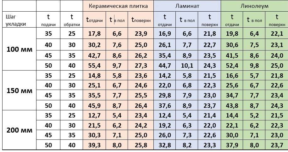
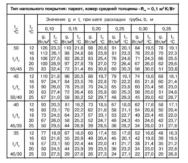
To determine the power of the water floor, it is necessary to find the product of the total area of \u200b\u200bthe room (m²), the temperature difference between the supply and return fluid, and coefficients depending on the material of the pipes, flooring (wood, linoleum, tiles, etc.), other elements of the system .
The power of a water heated floor per 1 m², or heat transfer, should not exceed the level of heat loss, but not more than 25%. If the value is too small or too large, it is necessary to recalculate by choosing a different pipe diameter and distance between the contour threads.
The power indicator is the higher, the larger the diameter of the selected pipes, and the lower, the larger the pitch is set between the threads.To save time, you can use electronic calculators for calculating the water floor or download a special program.
Calculations
You can calculate the water floor on your own or with the help of special programs. Most often, these are online calculators that installation companies offer on their websites. More serious programs need to be downloaded and installed on your computer. Of the most accessible, it should be noted RAUCAD / RAUWIN 7.0 (from the manufacturer of profiles and polymer pipes REHAU). And carrying out complex design on the universal Loop CAD2011 software, you will have both digital values and a scheme for laying a water-heated floor at the output.
In most cases, the following information is required for a complete calculation:
- the area of the heated room;
- material of load-bearing structures, walls and ceilings, their thermal resistance;
- thermal insulation material used as a base for underfloor heating;
- type of flooring;
- boiler power;
- maximum and operating temperature of the coolant;
- diameter and material of pipes for installing a water-heated floor, etc.
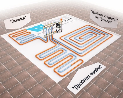
Pipe laying is recommended to be designed in the following ways:
- A spiral (snail) is the best option for placing communications for large areas - their coatings will warm up evenly. Pipe laying starts from the center of the room in a spiral. Return and supply run parallel to each other.
- snake. It is advisable to use it for heating small rooms: bathrooms, toilets, kitchens. The highest temperature of the flooring will be at the beginning of the circuit, so it is recommended to start from the outside wall or window.
- Double snake. Well suited for a medium-sized room - 15-20 m2.The return and supply are placed parallel to the far wall, which allows for a more even distribution of heat throughout the room.
Selection of pipes and manifold assembly
An analysis of all types of pipes showed that the best option is products made of reinforced polymer with the PERT marking and cross-linked polyethylene, which have the PEX designation.
Moreover, in the matter of laying heating systems in the area of \u200b\u200bfloors, PEX is still better, since they are elastic and work perfectly in low-temperature circuits.
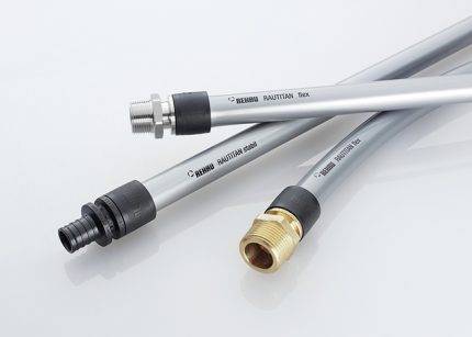 Rehau PE-Xa cross-pierced pipes are characterized by optimum flexibility. For ease of installation, the products are equipped with axial fittings. Maximum density, memory effect and slip ring fittings are excellent features for use in underfloor heating systems
Typical dimensions of pipes: diameter 16, 17 and 20 mm, wall thickness - 2 mm. If you prefer high quality, we recommend the brands Uponor, Tece, Rehau, Valtec. Sewn polyethylene pipes can be replaced with metal-plastic or polypropylene products.
In addition to pipes, which are inherently heating devices, you will need a collector-mixing unit that distributes the coolant along the circuits. It also has additional useful functions: removes air from pipes, regulates water temperature, and controls flow.
The design of the collector assembly is quite complex and consists of the following parts:
- manifolds with balancing valves, shut-off valves and flow meters;
- automatic air vent;
- a set of fittings for connecting individual elements;
- drainage drain taps;
- fixing brackets.
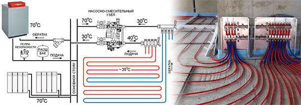
If the underfloor heating is connected to a common riser, the mixing unit must be equipped with a pump, a bypass and a thermostatic valve. There are so many possible devices that it is better to consult a specialist to select a design.
For ease of maintenance and additional protection, the manifold-mixing unit is placed in a cabinet located in an accessible place. It can be disguised in a niche, built-in wardrobe or dressing room, and also left open
It is desirable that all circuits extending from the collector assembly have the same length and are close to each other.
Design principles
When calculating a water heated floor, you must consider:
- only the active area of the system, under which the heated pipes are located, and not the entire quadrature of the room;
- step and method of laying a pipeline with water in concrete;
- screed thickness - a minimum of 45 mm above the pipes;
- requirements for the temperature difference in the supply and return - 5–10 0С are considered optimal values;
- water should move in the system at a speed of 0.15–1 m / s - a pump should be selected that meets these requirements;
- the length of the pipes in a separate TP circuit and the entire heating system.
Every 10 mm of screed is approximately 5–8% of heat loss for concrete heating. It is worth pouring it with a layer of more than 5-6 cm above the pipes only as a last resort, when increased strength of the rough base is required.
Ways to adjust contours
Pipes in the floor heating circuit are laid:
- snake (loops);
- spiral (snail);
- double helix;
- in a combined way.
The first option is the easiest to implement. However, when laying pipes with a “snake”, the water temperature at the beginning of the circuit and at the end will differ by 5–10 0С.And this is a fairly noticeable difference, which is felt with bare feet. Therefore, in most cases, it is recommended to choose a "spiral" or combine methods to ensure approximately equal temperature conditions throughout the floor.

Laying methods
insulation
As a heat-insulating material under the pipes, it is best to put extruded polystyrene foam (EPS). This is a moisture-resistant and durable insulation that is easy to install and easily tolerates contact with an alkaline cement mortar.


The thickness of the XPS boards is selected as follows:
- 30 mm - if the floor below is a heated room;
- 50 mm - for the first floors;
- 100 mm or more - if the floors are laid on the ground.
Floor insulation
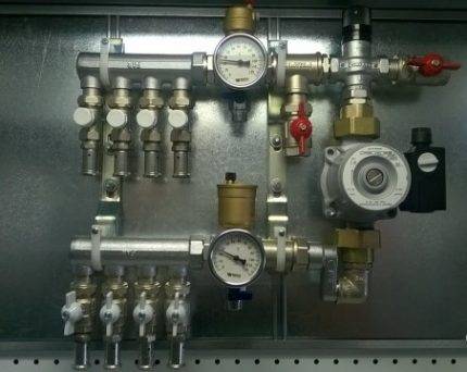
Collector-mixing unit
One of the main elements of the water floor is a mixing unit with a manifold, shut-off valves, an air vent, a thermometer, a thermostat and a bypass. A circulation pump is placed directly in its composition or in front of it.
If the TP is adjusted manually in the plans, then the connection of the circuits to the collector can be done through simple valves. Otherwise, you will have to install thermostats and electric valves on each outlet.
The manifold and mixing unit allows precise control of the water temperature in each circuit and, thanks to the bypass, protects the boiler from overheating. It is installed in a special closet or a niche in a room with a warm floor. Moreover, if the setting of this unit is performed incorrectly, then a hot frying pan may turn out under your feet, but there will not be enough heat in the room. It is on him that the efficiency of the entire floor heating system depends.
Collector assembly
Possible ways of laying the contour
In order to determine the pipe consumption for arranging a warm floor, you should decide on the layout of the water circuit. The main task of layout planning is to ensure uniform heating, taking into account the cold and unheated areas of the room.
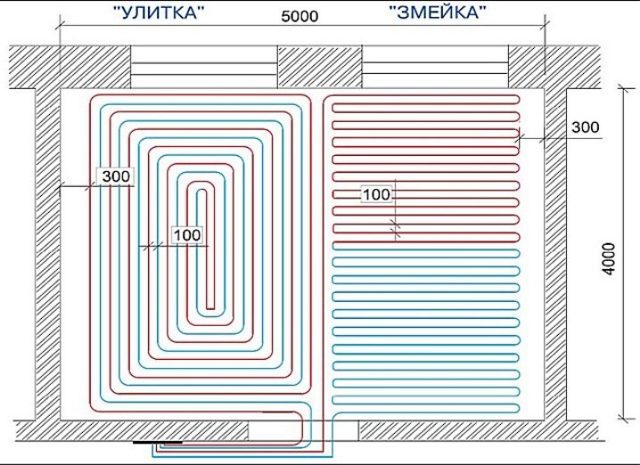
The following layout options are possible: snake, double snake and snail. When choosing a scheme, it is necessary to take into account the dimensions, configuration of the room and the location of the external walls
Method #1 - snake
The coolant is supplied to the system along the wall, passes through the coil and returns to the distribution manifold. In this case, half of the room is heated with hot water, and the rest is chilled.
When laying with a snake, it is impossible to achieve uniform heating - the temperature difference can reach 10 ° C. The method is applicable in narrow spaces.
The corner serpentine scheme is optimally suited if it is necessary to insulate the cold zone at the end wall or in the hallway as much as possible
Double serpentine allows you to achieve a softer temperature transition. The forward and reverse circuits run parallel to each other.
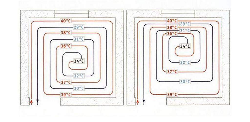
Method # 2 - snail or spiral
This is considered the optimal scheme for ensuring uniform heating of the floor covering. Direct and reverse branches are stacked alternately.
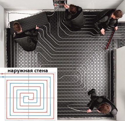
An additional plus of "shells" is the installation of a heating circuit with a smooth turn of the bend. This method is relevant when working with pipes of insufficient flexibility.
On large areas, a combined scheme is implemented. The surface is divided into sectors and a separate circuit is developed for each, going to a common collector. In the center of the room, the pipeline is laid out with a snail, and along the outer walls - with a snake.
We have another article on our website, in which we examined in detail the wiring diagrams for laying underfloor heating and provided recommendations on choosing the best option, depending on the characteristics of a particular room.
Final part
A warm water floor, or rather its power and other necessary indicators, can be calculated using a special calculator or seek help from a special company that will help make the necessary calculations. This must be done before the purchase of major pieces of equipment or materials. To do this, you should first determine whether the system will be only an auxiliary heating device or the main one. Power and possible loads are calculated based on the general characteristics, temperature, humidity and square of the room. The dimensions of the pipes, the step between them and their length will also depend on them.
Calculation of the power of the water floor
Calculations of the heating water system must be made with the utmost care. Any mistakes in the future can lead to additional costs, since they can be corrected only with the complete or partial dismantling of the screed, and this can damage the interior decoration of the room.
Before proceeding with the calculation of the amount of power, you need to know several parameters.
Parameters for the water floor
The power of the heating system is influenced by several factors, such as:
- pipeline diameter;
- pump power;
- area of the room;
- type of flooring.
These parameters also help to calculate the length of pipes for underfloor heating and their branches for space heating.
But how is power calculated?
Power calculation methodology
It is very difficult to independently make power calculations, since skill and experience are required here. For these reasons, it is better to order it from the appropriate organization where process engineers work. If, nevertheless, the calculation is made independently, then 100 watts per square meter are taken as the average value. This technique is used in multi-storey buildings.


In private houses, the average power will depend on the area of the building. Thus, the experts compiled the following indicators:
- area up to 150 sq. m. - 120 W / m2;
- area from 150 to 300 sq. m. - 100 W / m2;
- area from 300 to 500 sq. m. - 90 W / m2.
Having considered the methodology for calculating the power, you need to calculate the number of pipes. But for this, you should first familiarize yourself with the methods of installing them.
Calculation taking into account furniture
Experts recommend laying a warm floor only where there will be no bulky pieces of furniture - cabinets, fireplaces, sofas, etc. Accordingly, it is necessary to take into account when calculating the place where there will be no warm floor. For this we use the formula:
(S - S1) / H x 1.1 + D x 2 = L
In this formula (all values are in meters):
- L - Required pipe length;
- S - the total area of the premises;
- S1 - The total area of \u200b\u200bthe room where there will be no underfloor heating (empty areas);
- H - Step between pipes;
- D - Distance from the room to the collector.
An example of calculating the length of underfloor heating pipes with empty sections
- The length of the room is 4 meters;
- The width of the room is 3.5 meters;
- The distance between the pipes is 20 cm;
- Distance to the collector - 2.5 meters;
The room contains:
- Sofa measuring 0.8 x 1.8 meters;
- Wardrobe, dimensions 0.6 x 1.5 meters.
We calculate the area of the room: 4 x 3.5 \u003d 14 sq.m.
We consider the area of empty plots: 0.8 x 1.8 + 0.6 x 1.5 \u003d 2.34 sq.m.
We substitute the values \u200b\u200bin the formula and get: (14 - 2.34) / 0.2 x 1.1 + 2.5 x 2 \u003d 69.13 linear meters of pipes.
Conclusions and useful video on the topic
About the calculation and installation of a warm hydraulic floor, this video:
The video provides practical recommendations for laying the floor. The information will help to avoid mistakes that amateurs usually make:
The calculation makes it possible to design a "warm floor" system with optimal performance. It is permissible to install heating using passport data and recommendations.
It will work, but professionals still advise to spend time on the calculation, so that in the end the system consumes less energy.
Do you have experience in calculating underfloor heating and preparing a heating circuit project? Or have questions about the topic? Please share your opinion and leave comments.


