- Boiler selection
- Boiler power calculation
- Simple pipeline of constant cross section
- Thermal calculation example
- How to calculate the optimal number and volumes of heat exchangers
- Formulas
- Coolant speed
- Thermal power
- Calculation of the heating system
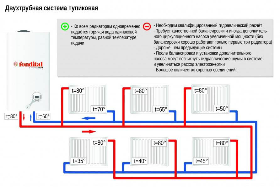
- Two-pipe heating system
- hydraulic balancing
- Determination of coolant flow and pipe diameters
- Calculation of the number of sections of heating devices
- Calculation steps
- Heat loss calculation
- Temperature conditions and selection of radiators
- Hydraulic calculation
- Boiler selection and some economics
- Selection and installation of heating devices
- The choice of boilers for heating a private house
- Determination of pressure losses in pipes
Boiler selection
The boiler can be of several types:
- Electric boiler;
- Liquid fuel boiler;
- Gas boiler;
- Solid fuel boiler;
- Combined boiler.
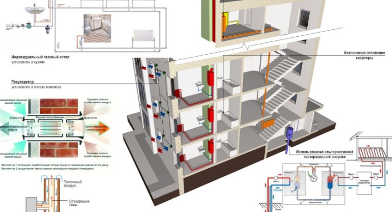
In addition to fuel costs, it will be necessary to carry out a preventive inspection of the boiler at least once a year. It is best to call a specialist for these purposes. You will also need to perform preventive cleaning of filters. The easiest to operate are boilers that run on gas. They are also quite cheap to maintain and repair. A gas boiler is suitable only in those houses that have access to a gas main.
Boilers of this class are distinguished by a high degree of safety.Modern boilers are designed in such a way that they do not require a special room for the boiler room. Modern boilers are characterized by a beautiful appearance and are able to successfully fit into the interior of any kitchen.
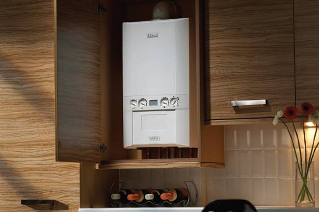 Gas boiler in the kitchen
To date, semi-automatic boilers operating on solid fuels are especially popular. True, such boilers have one drawback, which is that once a day it is necessary to load fuel. Many manufacturers produce such boilers that are fully automated. In such boilers, solid fuel is loaded offline.
However, such boilers are a bit more problematic. In addition to the main problem, which is that electricity is quite expensive now, they can also overload the network. In small villages, an average of up to 3 kW per hour is allocated per house, but this is not enough for a boiler, and it must be borne in mind that the network will be loaded not only with the operation of the boiler.
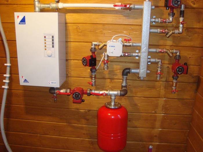 electric boiler
To organize the heating system of a private house, you can also install a liquid-fuel type of boiler. The disadvantage of such boilers is that they can cause criticism from the point of view of ecology and safety.
Boiler power calculation
Before you calculate the heating in the house, you need to do this by calculating the power of the boiler. The efficiency of the entire heating system will primarily depend on the power of the boiler. The main thing in this matter is not to overdo it, as a too powerful boiler will consume more fuel than necessary. And if the boiler is too weak, then it will not be possible to heat the house properly, and this will negatively affect the comfort in the house.
Therefore, the calculation of the heating system of a country house is important.You can choose a boiler of the required power if you simultaneously calculate the specific heat loss of the building for the entire heating period
Calculation of home heating - specific heat loss can be done by the following method:
qhouse=Qyear/Fh
Qyear is the consumption of heat energy for the entire heating period;
Fh is the area of the house that is heated;
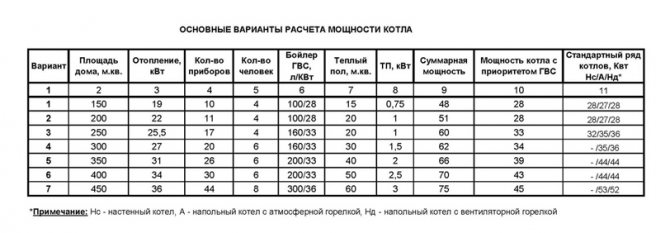
Boiler power selection table depending on the area to be heated
In order to calculate the heating of a country house - the energy consumption that will go to heating a private house, you need to use the following formula and a tool such as a calculator:
Qyear=βh*[Qk-(Qvn b+Qs)*ν
βh - this is the coefficient for accounting for additional heat consumption by the heating system.
Qvn b - heat receipts of a domestic nature, which are typical for the entire heating period.
Qk is the value of the total house heat loss.
Qs - this is the flow of heat in the form of solar radiation that enters the house through the windows.
Before you calculate the heating of a private house, it is worth considering that different types of premises are characterized by different temperature conditions and air humidity indicators. They are presented in the following table:
The following is a table that shows the shading coefficients of a light-type opening and the relative amount of solar radiation that enters through the windows.
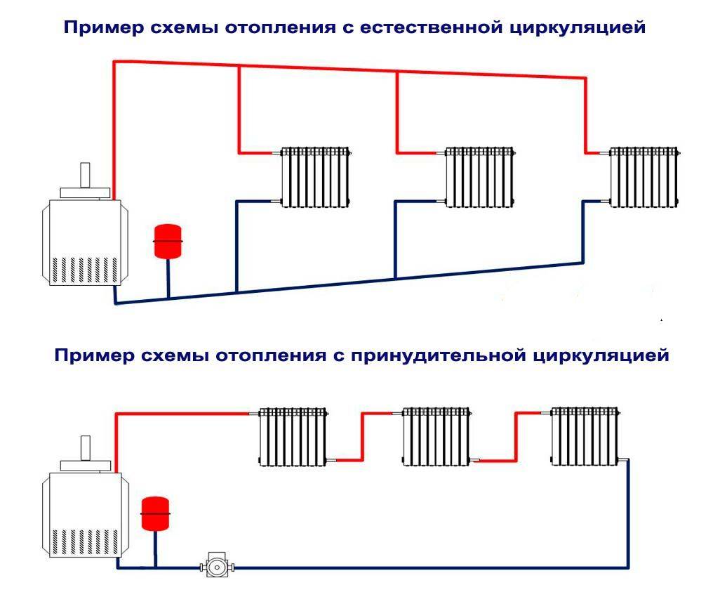
If you plan to install water heating, then the area of \u200b\u200bthe house will be largely a determining factor. If the house has a total area of not more than 100 square meters. meters, then a heating system with natural circulation is also suitable. If the house has a larger area, then a heating system with forced circulation is mandatory.The calculation of the heating system of the house must be carried out accurately and correctly.
Simple pipeline of constant cross section
The main design ratios for a simple pipeline are: Bernoulli equation, flow equation Q \u003d const and formulas for calculating friction pressure losses along the length of the pipe and in local resistances.
When applying the Bernoulli equation in a particular calculation, the following recommendations can be taken into account. First, you should set two design sections and a comparison plane in the figure. It is recommended to take as sections:
the free surface of the liquid in the tank, where the velocity is zero, i.e. V = 0;
the outlet of the flow into the atmosphere, where the pressure in the jet cross section is equal to the ambient pressure, i.e. pa6c = ratm or pis6 = 0;
section in which the pressure is set (or needs to be determined) (readings of a pressure gauge or vacuum gauge);
section under the piston, where the excess pressure is determined by the external load.
The comparison plane is conveniently drawn through the center of gravity of one of the calculated sections, usually located below (then the geometric heights of the sections are 0).
Let a simple pipeline of constant cross section be located arbitrarily in space (Fig. 1), have a total length l and a diameter d, and contain a number of local resistances. In the initial section (1-1), the geometric height is equal to z1 and the overpressure p1, and in the final (2-2), respectively, z2 and p2. The flow velocity in these sections due to the constancy of the pipe diameter is the same and equal to v.
The Bernoulli equation for sections 1-1 and 2-2, taking into account , will look like:
or
,
sum of coefficients of local resistances.
For the convenience of calculations, we introduce the concept of design head
,
٭
٭٭
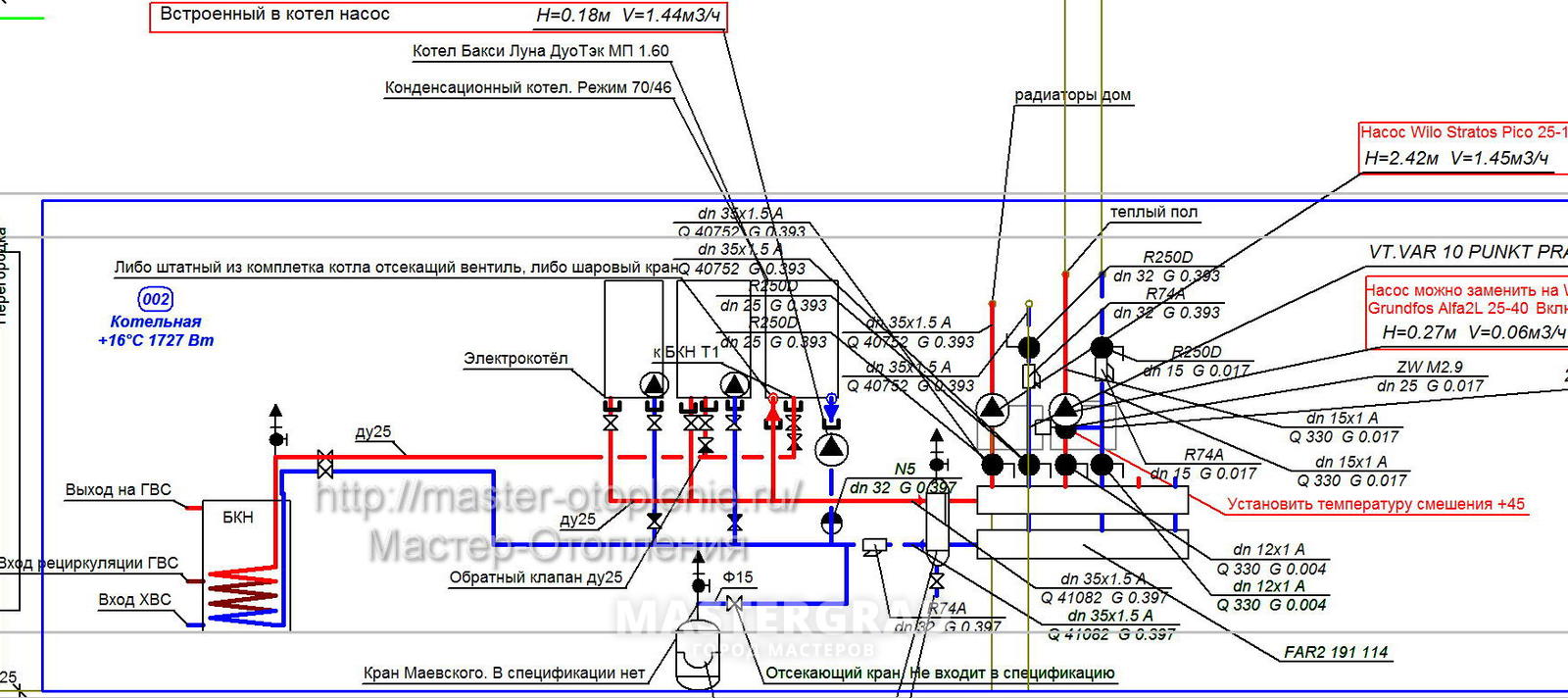
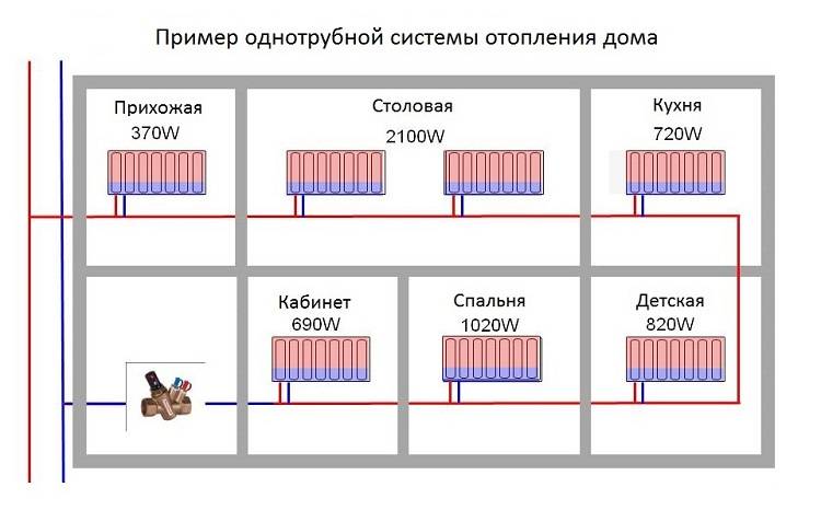
Thermal calculation example
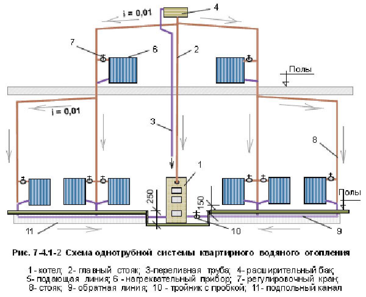
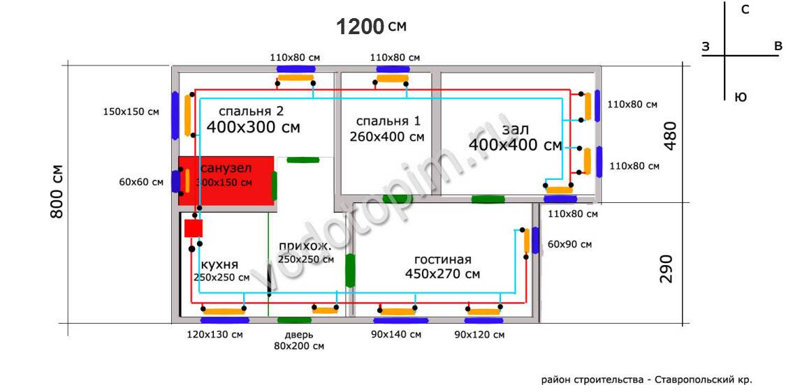
As an example of a thermal calculation, there is an ordinary 1-storey house with four living rooms, a kitchen, a bathroom, a “winter garden” and utility rooms.
Foundation from a monolithic reinforced concrete slab (20 cm), external walls - concrete (25 cm) with plaster, roof - ceilings from wooden beams, roof - metal tiles and mineral wool (10 cm)
Let us designate the initial parameters of the house necessary for the calculations.
Building dimensions:
- floor height - 3 m;
- small window of the front and back of the building 1470 * 1420 mm;
- large facade window 2080*1420 mm;
- entrance doors 2000*900 mm;
- rear doors (exit to the terrace) 2000*1400 (700 + 700) mm.
The total width of the building is 9.5 m2, the length is 16 m2. Only living rooms (4 units), a bathroom and a kitchen will be heated.
For an accurate calculation of heat loss on the walls, the area of \u200b\u200ball windows and doors must be subtracted from the area of \u200b\u200bthe external walls - this is a completely different type of material with its own thermal resistance
We start by calculating the areas of homogeneous materials:
- floor area - 152 m2;
- roof area - 180 m2, given the height of the attic 1.3 m and the width of the run - 4 m;
- window area - 3*1.47*1.42+2.08*1.42=9.22 m2;
- door area - 2*0.9+2*2*1.4=7.4 m2.
The area of the outer walls will be equal to 51*3-9.22-7.4=136.38 m2.
We turn to the calculation of heat loss on each material:
- Qfloor\u003d S * ∆T * k / d \u003d 152 * 20 * 0.2 / 1.7 \u003d 357.65 W;
- Qroof\u003d 180 * 40 * 0.1 / 0.05 \u003d 14400 W;
- Qwindow=9.22*40*0.36/0.5=265.54W;
- Qdoors=7.4*40*0.15/0.75=59.2W;
And also Qwall equivalent to 136.38*40*0.25/0.3=4546. The sum of all heat losses will be 19628.4 W.
As a result, we calculate the power of the boiler: Pboiler=Qlosses*Sroom_heating*K/100=19628.4*(10.4+10.4+13.5+27.9+14.1+7.4)*1.25/100=19628.4*83.7*1.25/100=20536.2=21 kW.
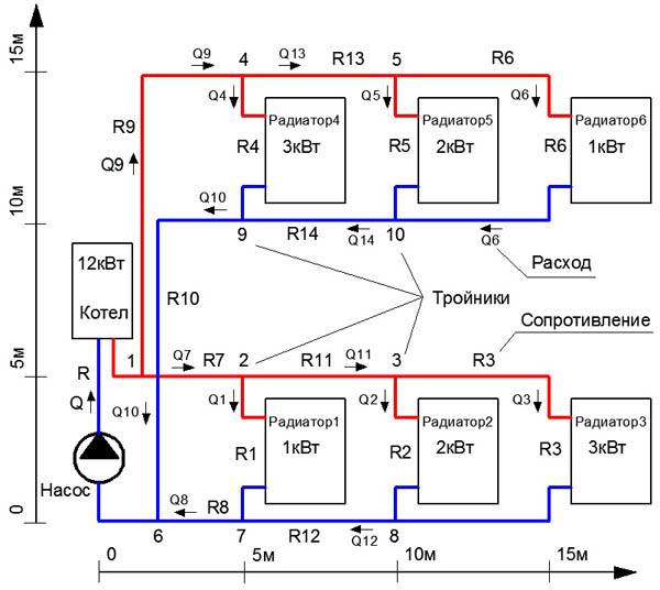
Let's calculate the number of radiator sections for one of the rooms. For all others, the calculations are similar. For example, a corner room (on the left, lower corner of the diagram) has an area of 10.4 m2.
So N=(100*k1*k2*k3*k4*k5*k6*k7)/C=(100*10.4*1.0*1.0*0.9*1.3*1.2*1.0*1.05)/180=8.5176=9.
This room requires 9 sections of a heating radiator with a heat output of 180 watts.
We proceed to the calculation of the amount of coolant in the system - W=13.5*P=13.5*21=283.5 l. This means that the coolant velocity will be: V=(0.86*P*μ)/∆T=(0.86*21000*0.9)/20=812.7 l.
As a result, the full turnover of the entire volume of the coolant in the system will be equivalent to 2.87 times per hour.
- Calculation of the heating system of a private house: rules and examples of calculation
- Thermal engineering calculation of a building: specifics and formulas for performing calculations + practical examples
How to calculate the optimal number and volumes of heat exchangers
When calculating the number of required radiators, one should take into account what material they are made of. The market now offers three types of metal radiators:
- Cast iron,
- Aluminum,
- bimetallic alloy.
All of them have their own characteristics. Cast iron and aluminum have the same heat transfer rate, but aluminum cools quickly, and cast iron heats up slowly, but retains heat for a long time. Bimetallic radiators heat up quickly, but cool down much slower than aluminum ones.
When calculating the number of radiators, other nuances should also be taken into account:
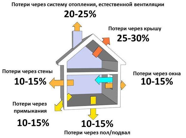
- thermal insulation of the floor and walls helps to save up to 35% of heat,
- the corner room is cooler than the others and needs more radiators,
- the use of double-glazed windows on windows saves 15% of heat energy,
- up to 25% of heat energy “leaves” through the roof.

The number of heating radiators and sections in them depends on many factors.
In accordance with the norms of SNiP, 100 W of heat is required to heat 1 m3. Therefore, 50 m3 will require 5000 watts. If a bimetallic device for 8 sections emits 120 W, then using a simple calculator we calculate: 5000: 120 = 41.6. After rounding up, we get 42 radiators.
You can use the approximate formula for calculating radiator sections:
N*= S/P *100
The symbol (*) shows that the fractional part is rounded according to general mathematical rules, N is the number of sections, S is the area of the room in m2, and P is the heat output of 1 section in W.
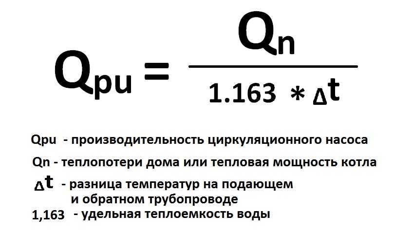
Formulas
Because we, dear reader, do not encroach on obtaining a diploma in thermal engineering, we will not start to climb into the jungle.
A simplified calculation of the diameter of the heating pipeline is performed according to the formula D \u003d 354 * (0.86 * Q / Dt) / v, in which:
- D is the desired value of the diameter in centimeters.
- Q is the thermal load on the corresponding section of the circuit.
- Dt is the temperature delta between the supply and return pipelines. In a typical autonomous system, it is approximately 20 degrees.
- v is the coolant flow rate in the pipes.
Looks like we don't have enough data to continue.
In order to calculate the diameter of pipes for heating, we need:
- Find out how fast the coolant can move.
- Learn to calculate the thermal power of the entire system and its individual sections.
Coolant speed
It must comply with a pair of boundary conditions.
On the one hand, the coolant must turn around in the circuit approximately three times per hour.In another case, the cherished temperature delta will increase noticeably, making the heating of the radiators uneven. In addition, in extreme cold, we will take full advantage of the real possibility of defrosting the coolest parts of the circuit.
Otherwise, excessively high speed will generate hydraulic noise. Falling asleep to the sound of water in the pipes is a pleasure, let's say, for an amateur.
The range of flow rates from 0.6 to 1.5 meters per second is considered acceptable; along with this, in most cases, the maximum allowable value is used in calculations - 1.5 m / s.
Thermal power
Here is a scheme for calculating it for the normalized thermal resistance of walls (for the center of the country - 3.2 m2 * C / W).
- For a private house, 60 watts per cubic meter of space are taken as the base power.
- To these are added 100 watts for each window and 200 for each door.
- The result is multiplied by a regional coefficient depending on the climatic territory:
| January average temperature | Coefficient |
| -40 | 2,0 |
| -25 | 1,6 |
| -15 | 1,4 |
| -5 | 1 |
| 0,8 |
So, a room of 300 m2 with three doors and windows in Krasnodar (average January temperature is +0.6C) will require (300 * 60 + (3 * 100 + 200)) * 0.8 = 14800 watts of heat.
For buildings, the thermal resistance of the walls of which differs significantly from the normalized one, another simplified scheme is used: Q=V*Dt*K/860, where:
- Q is the need for thermal power in kilowatts.
- V - the amount of heated space in cubic meters.
- Dt - temperature difference between the street and the room at the peak of cold weather.
| Insulation coefficient | Description of building envelopes |
| 0,6 — 0,9 | Foam or mineral wool coat, insulated roof, energy-saving triple glazing |
| 1,-1,9 | Masonry in one and a half bricks, single-chamber double-glazed windows |
| 2 — 2,9 | Brickwork, timber-framed windows without insulation |
| 3-4 | Laying in half a brick, glazing in one thread |
Where to get the load for a separate section of the circuit? It is calculated by the volume of the room that is heated by this area, using one of the above methods.
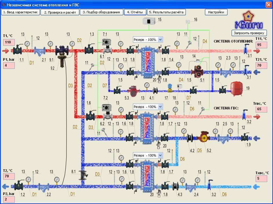
Calculation of the heating system
When planning a heating system for a private house, the most difficult and crucial step is to carry out hydraulic calculations - you need to determine the resistance of the heating system.
After all, taking on their own how to calculate the volume of the heating system, and further plan the system, few people know that it is first necessary to carry out some graphic design work. In particular, the following parameters should be determined and displayed on the heating system plan:
heat balance of the premises in which heating devices will be located;
the type of the most suitable heating appliances and heat exchange surfaces, indicate them on the preliminary plan of the heating system;
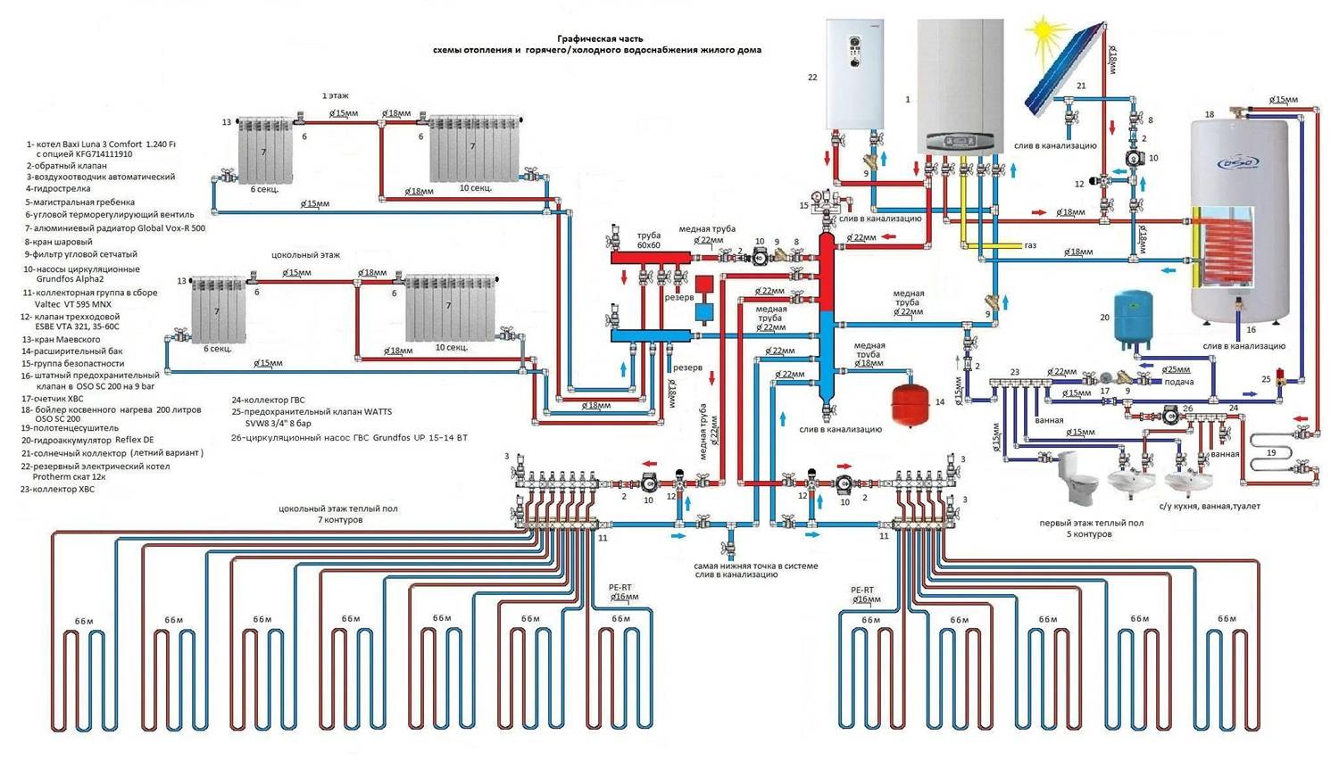
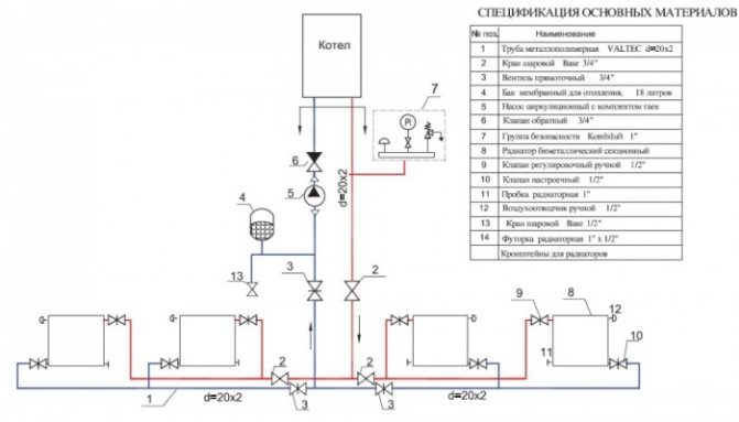
the most suitable type of heating system, choose the most suitable configuration. You should also create a detailed layout of the heating boiler, pipeline.
choose the type of pipeline, determine the additional elements necessary for high-quality work (valves, valves, sensors). Indicate their location on the preliminary scheme of the system.
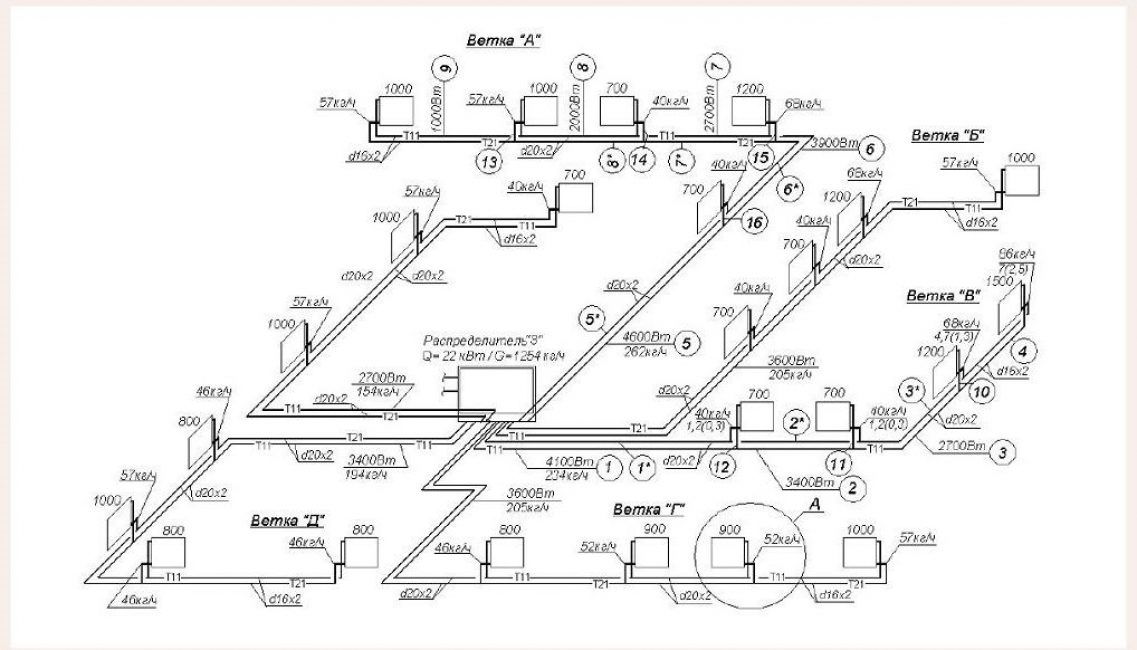
create a complete axonometric diagram. It should indicate the numbers of sections, their duration and the level of heat load.
plan and display on the diagram the main heating circuit
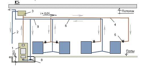
In this case, it is important to take into account the maximum flow rate of the coolant.
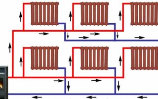
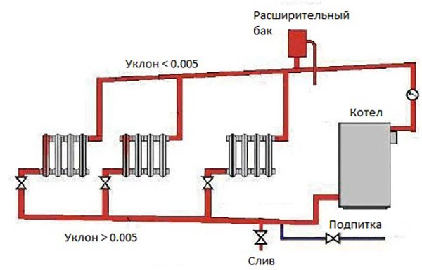
Schematic diagram of heating
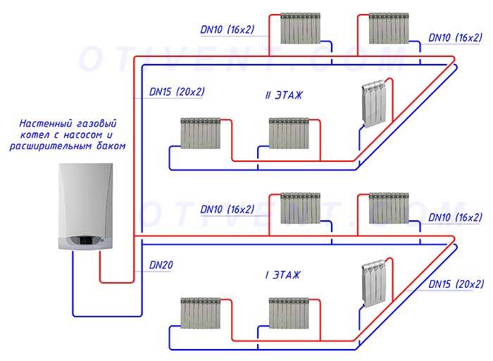
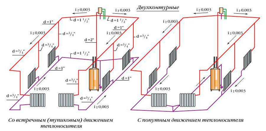
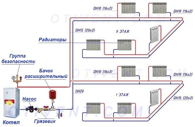
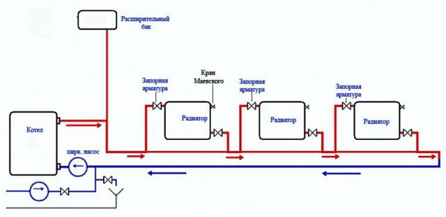
Two-pipe heating system
For any heating system, the design section of the pipeline is the segment on which the diameter does not change and where a stable coolant flow occurs. The last parameter is calculated from the heat balance of the room.
To calculate a two-pipe heating system, a preliminary numbering of the sections should be carried out. It starts with a heating element (boiler). All nodal points of the supply line, at which the system branches, must be marked in capital letters.
 Two-pipe heating system
The corresponding nodes located on the prefabricated main pipelines should be indicated by dashes. The branch points of instrument branches (on the nodal riser) are most often indicated by Arabic numerals. These designations correspond to the floor number (in case a horizontal heating system is implemented) or the riser number (vertical system). In this case, at the junction of the coolant flow, this number is indicated by an additional stroke.

For the best possible performance of the work, each section should be numbered.
It is important to take into account that the number must consist of two values - the beginning and end of the section
hydraulic balancing
Balancing of pressure drops in the heating system is carried out by means of control and shut-off valves.
 Hydraulic balancing of the system is carried out on the basis of:
- design load (mass coolant flow rate);
- pipe manufacturers data on dynamic resistance;
- the number of local resistances in the area under consideration;
- technical characteristics of fittings.
Installation characteristics - pressure drop, mounting, capacity - are set for each valve. They determine the coefficients of coolant flow into each riser, and then into each device.
The pressure loss is directly proportional to the square of the coolant flow rate and is measured in kg/h, where
S is the product of the dynamic specific pressure, expressed in Pa / (kg / h), and the reduced coefficient for the local resistance of the section (ξpr).
The reduced coefficient ξpr is the sum of all local resistances of the system.
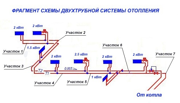
Determination of coolant flow and pipe diameters
First, each heating branch must be divided into sections, starting from the very end. The breakdown is done by water consumption, and it varies from radiator to radiator. This means that after each battery a new section begins, this is shown in the example that is presented above. We start from the 1st section and find the mass flow rate of the coolant in it, focusing on the power of the last heater:
G = 860q/ ∆t, where:
- G is the coolant flow rate, kg/h;
- q is the thermal power of the radiator in the area, kW;
- Δt is the temperature difference in the supply and return pipelines, usually take 20 ºС.
For the first section, the calculation of the coolant looks like this:
860 x 2 / 20 = 86 kg/h.
The result obtained must be immediately applied to the diagram, but for further calculations we will need it in other units - liters per second. To make a transfer, you need to use the formula:
GV = G /3600ρ, where:
- GV – water volume flow, l/s;
- ρ is the density of water, at a temperature of 60 ºС it is equal to 0.983 kg / liter.
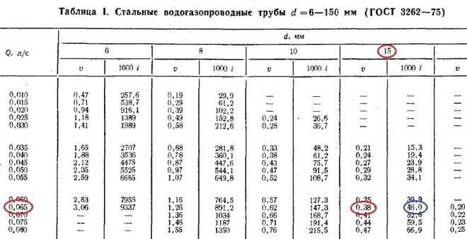
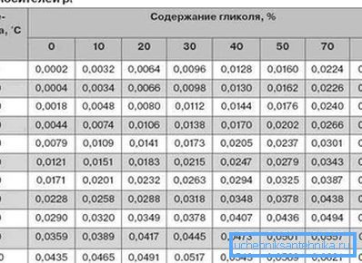
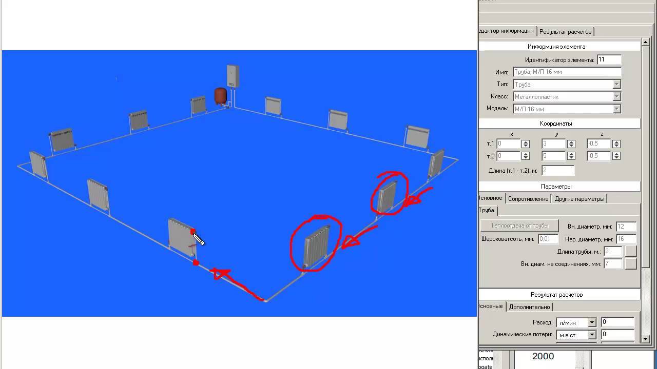
In these tables, the values of the diameters of steel and plastic pipes are published, depending on the flow rate and speed of the coolant.If you turn to page 31, then in table 1 for steel pipes, the first column shows the flow rates in l / s. In order not to make a complete calculation of pipes for the heating system of a frequent house, you just need to select the diameter according to the flow rate, as shown in the figure below:
So, for our example, the internal size of the passage should be 10 mm. But since such pipes are not used in heating, we safely accept the DN15 (15 mm) pipeline. We put it on the diagram and go to the second section. Since the next radiator has the same capacity, there is no need to apply the formulas, we take the previous water flow and multiply it by 2 and get 0.048 l / s. Again we turn to the table and find the nearest suitable value in it. At the same time, do not forget to monitor the speed of the water flow v (m / s) so that it does not exceed the specified limits (in the figures it is marked in the left column with a red circle):
As you can see in the figure, section No. 2 is also laid with a DN15 pipe. Further, according to the first formula, we find the flow rate in section No. 3:
860 x 1.5 / 20 = 65 kg / h and convert it to other units:
65 / 3600 x 0.983 = 0.018 l / s.
Adding it to the sum of the costs of the two previous sections, we get: 0.048 + 0.018 = 0.066 l / s and again turn to the table. Since in our example we do not calculate the gravitational system, but the pressure system, then the DN15 pipe is suitable for the speed of the coolant this time too:
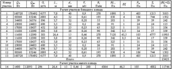
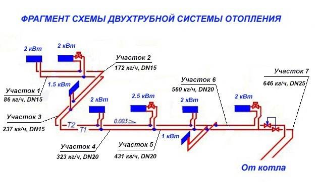
Going in this way, we calculate all the sections and apply all the data to our axonometric diagram:
Calculation of the number of sections of heating devices
The heating system will not be effective if the optimal number of radiator sections is not calculated.Incorrect calculation will lead to the fact that the rooms will be heated unevenly, the boiler will work at the limit of its capabilities or, conversely, “idle” wasting fuel.
Some homeowners believe that the more batteries, the better. However, this lengthens the path of the coolant, which gradually cools, which means that the last rooms in the system run the risk of being left without heat. Forced circulation of the coolant, in part, solves this problem. But we must not lose sight of the power of the boiler, which may simply “not pull” the system.


To calculate the number of sections, you need the following values:
- the area of the heated room (plus the adjacent one, where there are no radiators);
- power of one radiator (indicated in the technical specification);
take into account that for 1 sq. m
living space will require 100 W of power for central Russia (according to the requirements of SNiP).
The area of \u200b\u200bthe room is multiplied by 100 and the resulting amount is divided by the power parameters of the installed radiator.
An example for a room of 25 square meters. meters and radiator power 120 W: (20x100) / 185 = 10.8 = 11
This is the simplest formula, with a non-standard height of rooms or their complex configuration, other values \u200b\u200bare used.
How to correctly calculate the heating in a private house if the power of the radiator is unknown for some reason? By default, the average static power of 200 watts is taken. You can take the average values of certain types of radiators. For bimetallic, this figure is 185 W, for aluminum - 190 W. For cast iron, the value is much lower - 120 watts.
If the calculation is carried out for corner rooms, then the result can be safely multiplied by a factor of 1.2.
Calculation steps
It is necessary to calculate the parameters of heating a house in several stages:
- calculation of heat loss at home;
- selection of temperature regime;
- selection of heating radiators by power;
- hydraulic calculation of the system;
- boiler selection.
The table will help you understand what kind of radiator power you need for your room.
Heat loss calculation
The thermotechnical part of the calculation is performed on the basis of the following initial data:
- specific thermal conductivity of all materials used in the construction of a private house;
- geometric dimensions of all elements of the building.
The heat load on the heating system in this case is determined by the formula:
Mk \u003d 1.2 x Tp, where
Tp - total heat loss of the building;
Mk - boiler power;
1.2 - safety factor (20%).
For individual buildings, heating can be calculated using a simplified method: the total area of the premises (including corridors and other non-residential premises) is multiplied by the specific climatic power, and the resulting product is divided by 10.
The value of the specific climatic power depends on the construction site and is equal to:
- for the central regions of Russia - 1.2 - 1.5 kW;
- for the south of the country - 0.7 - 0.9 kW;
- for the north - 1.5 - 2.0 kW.
A simplified technique allows you to calculate heating without resorting to expensive help from design organizations.
Temperature conditions and selection of radiators
The mode is determined based on the temperature of the coolant (most often it is water) at the outlet of the heating boiler, the water returned to the boiler, as well as the air temperature inside the premises.
The optimal mode, according to European standards, is the ratio 75/65/20.
To select heating radiators before installation, you must first calculate the volume of each room. For each region of our country, the required amount of thermal energy per cubic meter of space has been established. For example, for the European part of the country, this figure is 40 watts.
To determine the amount of heat for a particular room, it is necessary to multiply its specific value by cubic capacity and increase the result by 20% (multiply by 1.2). Based on the figure obtained, the required number of heaters is calculated. The manufacturer indicates their power.
For example, each fin of a standard aluminum radiator has a power of 150 W (at a coolant temperature of 70°C). To determine the required number of radiators, it is necessary to divide the required thermal energy by the power of one heating element.
Hydraulic calculation
For hydraulic calculation there are special programs.
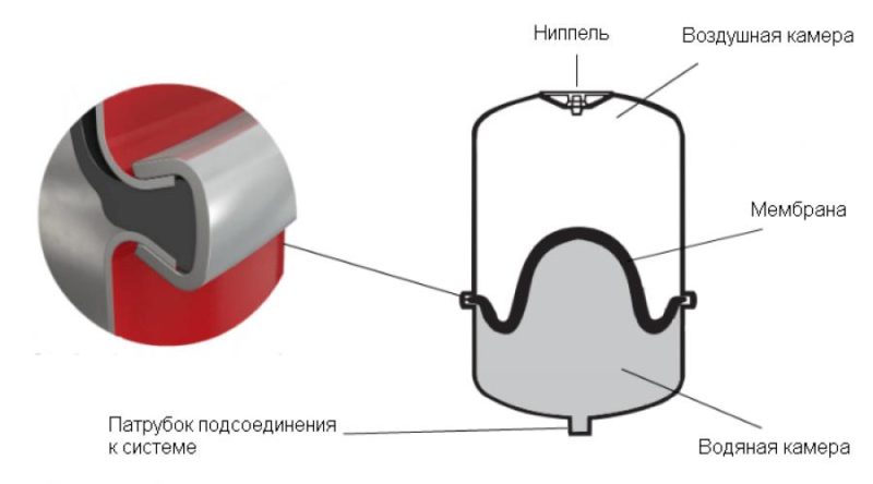
One of the costly stages of construction is the installation of the pipeline. A hydraulic calculation of the heating system of a private house is needed to determine the diameters of the pipes, the volume of the expansion tank and the correct selection of the circulation pump. The result of the hydraulic calculation are the following parameters:
- Heat carrier consumption as a whole;
- Loss of pressure of the heat carrier in the system;
- Pressure loss from the pump (boiler) to each heater.
How to determine the flow rate of the coolant? To do this, it is necessary to multiply its specific heat capacity (for water, this figure is 4.19 kJ / kg * deg. C) and the temperature difference at the outlet and inlet, then divide the total power of the heating system by the result.

The pipe diameter is selected based on the following condition: the water velocity in the pipeline should not exceed 1.5 m/s. Otherwise, the system will make noise. But there is also a lower speed limit - 0.25 m / s. The installation of the pipeline requires the evaluation of these parameters.
If this condition is neglected, then airing of the pipes may occur. With properly selected sections, a circulation pump built into the boiler is sufficient for the functioning of the heating system.
The head loss for each section is calculated as the product of the specific friction loss (specified by the pipe manufacturer) and the length of the pipeline section. In the factory specifications, they are also indicated for each fitting.
Boiler selection and some economics
The boiler is selected depending on the degree of availability of a particular type of fuel. If gas is connected to the house, it makes no sense to purchase solid fuel or electric. If you need the organization of hot water supply, then the boiler is not chosen according to the heating power: in such cases, the installation of two-circuit devices with a power of at least 23 kW is chosen. With less productivity, they will provide only one point of water intake.
Selection and installation of heating devices
Heat is transferred from the boiler to the premises by means of heating devices. They are divided into:
- infrared emitters;
- convective-radiation (all types of radiators);
- convective (ribbed).
Infrared emitters are less common, but are considered more efficient, since they do not heat the air, but objects that are in the area of the emitter. For home use, portable infrared heaters are known that convert electrical current into infrared radiation.
The devices from the last two points are most widely used due to their optimal consumer qualities.
To calculate the required number of sections of the heater, it is necessary to know the amount of heat transfer from each section.
Approximately 100 W of power is needed per 1 m². For example, if the power of one section of the radiator is 170 W, then a radiator of 10 sections (1.7 kW) can heat a room area of 17 m². At the same time, the default ceiling height is assumed to be no more than 2.7 m.
By placing the radiator in a deep niche under the window sill, you reduce heat transfer by an average of 10%. When placed on top of a decorative box, heat loss reaches 15-20%.
By adhering to simple rules, you can increase the heat transfer efficiency of heating radiators:
- for maximum neutralization of cold air flows with warm air, radiators are installed strictly under the windows, keeping a distance between them of at least 5 cm.
- The center of the window and the radiator must either coincide or deviate by no more than 2 cm;
- batteries in each room are placed at the same level horizontally;
- the distance between the radiator and the floor must be at least 6 cm;
- between the rear surface of the heater and the wall should be at least 2-5 cm.
The choice of boilers for heating a private house
The heaters that the house heating system scheme uses can be of the following types:
- Ribbed or convective;
- Radiative-convective;
- Radiation. Radiation heaters are rarely used to organize a heating system in a private house.
Modern boilers have the characteristics that are shown in the following table:
When heating is calculated in a wooden house, this table can help you to some extent. When installing heating devices, you must comply with some requirements:
- The distance from the heater to the floor must be at least 60 mm. Thanks to this distance, home heating scheme will allow you to clean in a hard-to-reach place.
- The distance from the heating device to the window sill must be at least 50 mm, so that the radiator can be removed without problems if something happens.
- The fins of the heating appliances must be in a vertical position.
- It is desirable to mount heaters under windows or near windows.
- The center of the heater must match the center of the window.
If there are several heaters in the same room, they must be located on the same level.
Determination of pressure losses in pipes
The pressure loss resistance in the circuit through which the coolant circulates is determined as their total value for all individual components. The latter include:
- losses in the primary circuit, denoted as ∆Plk;
- local heat carrier costs (∆Plm);
- pressure drop in special zones, called “heat generators” under the designation ∆Ptg;
- losses inside the built-in heat exchange system ∆Pto.
After summing these values, the desired indicator is obtained, which characterizes the total hydraulic resistance of the system ∆Pco.
In addition to this generalized method, there are other ways to determine the head loss in polypropylene pipes. One of them is based on a comparison of two indicators tied to the beginning and end of the pipeline. In this case, the pressure loss can be calculated by simply subtracting its initial and final values, determined by two pressure gauges.
Another option for calculating the desired indicator is based on the use of a more complex formula that takes into account all the factors that affect the characteristics of the heat flux. The ratio given below takes into account, first of all, fluid head loss due to the length of the pipeline.
- h is the liquid head loss, measured in meters in the case under study.
- λ is the coefficient of hydraulic resistance (or friction), determined by other calculation methods.
- L is the total length of the serviced pipeline, which is measured in running meters.
- D is the internal size of the pipe, which determines the volume of the coolant flow.
- V is the fluid flow rate, measured in standard units (meter per second).
- The symbol g is the free fall acceleration, which is 9.81 m/s2.

Of great interest are the losses caused by the high coefficient of hydraulic friction. It depends on the roughness of the inner surfaces of the pipes. The ratios used in this case are valid only for tubular blanks of a standard round shape. The final formula for finding them looks like this:
- V - the speed of movement of water masses, measured in meters / second.
- D - inner diameter, which determines the free space for the movement of the coolant.
- The coefficient in the denominator indicates the kinematic viscosity of the liquid.
The latter indicator refers to constant values and is found according to special tables published in large quantities on the Internet.