- Heater in the network: what is it for, and how to calculate its power
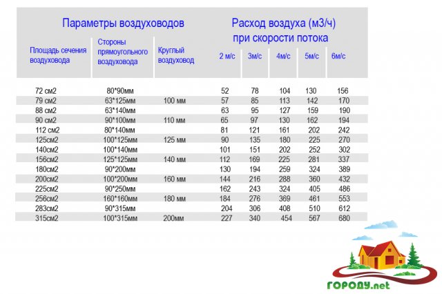
- Calculation of the section of air ducts by the method of permissible speeds
- Standard speed
- Example
- 4 Programs for help
- Calculation of supply and exhaust ventilation of a production facility
- Removing excess heat and harmful fumes
- Systems that normalize the level of humidity
- Ventilation at high concentration of people
- Calculation of air ducts or design of ventilation systems
- Calculation of the area of air ducts and fittings: planning a ventilation system
- Calculation of the section of air ducts by the method of permissible speeds
- Standard speed
- Example
- Calculator for calculation and selection of ventilation system components
- Why is it necessary to calculate the area of air ducts and fittings?
- Duct types
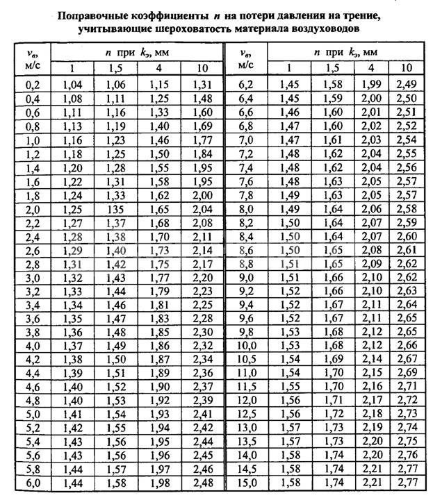
- Pressure loss
- An example of calculating ventilation using a calculator
- Conclusions and useful video on the topic
Heater in the network: what is it for, and how to calculate its power
If supply ventilation is planned, then in winter it is impossible to do without air heating. Modern systems allow you to adjust the fan performance, which helps in the cold season.By reducing the supply force, it is possible to achieve not only energy savings at a lower fan flow rate, but also the air, passing through the heater more slowly, will be warmer. However, calculations of the outdoor air heating temperature are still necessary. They are produced according to the formula:
ΔT = 2.98 × P / L, where:
- P - the power consumption of the heater, which should increase the air temperature from the street to 18 ° C (W);
- L - fan performance (m 3 / h).
Calculation of the section of air ducts by the method of permissible speeds
The calculation of the cross section of the ventilation duct by the allowable speed method is based on the normalized maximum speed. The speed is selected for each type of room and duct section, depending on the recommended values. For each type of building, there are maximum allowable velocities in the main ducts and branches, above which the use of the system is difficult due to noise and strong pressure losses.
Rice. 1 (Network diagram for calculation)
In any case, before starting the calculation, it is necessary to draw up a system plan. First you need to calculate the required amount of air that needs to be supplied and removed from the room. Further work will be based on this calculation.
The process of calculating the cross section by the method of permissible velocities simply consists of the following steps:
- A duct scheme is created, on which sections and the estimated amount of air that will be transported through them are marked. It is better to indicate on it all grilles, diffusers, section changes, turns and valves.
- According to the selected maximum speed and the amount of air, the cross-section of the duct, its diameter or the size of the sides of the rectangle is calculated.
- After all the parameters of the system are known, it is possible to select a fan of the required performance and pressure. Fan selection is based on the calculation of the pressure drop in the network. This is much more difficult than just choosing the cross section of the duct in each section. We will consider this question in general terms. Since sometimes they just pick up a fan with a small margin.
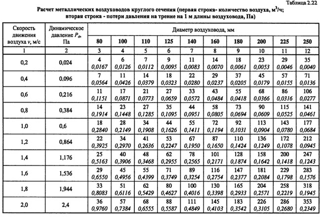
Standard speed
The values are approximate, but allow you to create a system with a minimum level of noise.
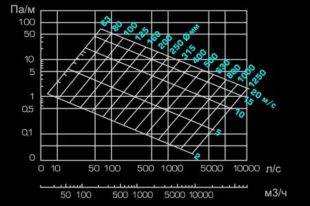
Fig, 2 (Nomogram of a round tin air duct)
How to use these values? They must be substituted into the formula or use nomograms (diagrams) for different shapes and types of air ducts.
Nomograms are usually given in the regulatory literature or in the instructions and descriptions of the air ducts of a particular manufacturer. For example, all flexible air ducts are equipped with such schemes. For tin pipes, data can be found in the documents and on the manufacturer's website.
In principle, you can not use a nomogram, but find the required cross-sectional area based on the air speed. And choose the area according to the diameter or width and length of a rectangular section.
Example
Consider an example. The figure shows a nomogram for a round tin duct. The nomogram is also useful in that it can be used to clarify the pressure loss in the duct section at a given speed. These data will be required in the future for the selection of a fan.
So, what kind of air duct to choose in the network section (branch) from the grid to the main, through which 100 m³ / h will be pumped? On the nomogram, we find the intersections of a given amount of air with the line of maximum speed for a branch of 4 m/s. Also, not far from this point, we find the nearest (larger) diameter.This is a pipe with a diameter of 100 mm.
In the same way, we find the cross section for each section. Everything is selected. Now it remains to select the fan and calculate the air ducts and fittings (if necessary for production).
4 Programs for help
To eliminate human factors in the calculations, as well as reduce the design time, several products have been developed that allow you to correctly determine the parameters of the future ventilation system. In addition, some of them allow the construction of a 3D model of the complex being created. Among them are the following developments:
- Vent-Calc for calculating cross-sectional area, thrust and resistance in sections.
- GIDRV 3.093 provides control over the calculation of channel parameters.
- Ducter 2.5 selects system elements according to certain characteristics.
- CADvent based on AutoCAD with a maximum database of elements.
Everyone solves the problem of selecting the dimensions of future ventilation independently. For an inexperienced installer, it will be preferable to design and install all components with the help of specialists who have experience in creating such highways and the appropriate equipment and fixtures.
Calculation of supply and exhaust ventilation of a production facility
In order to make a supply and exhaust ventilation project, the first step is to determine the source of harmful substances. Then it is calculated how much clean air is needed for the normal work of people and how much polluted air needs to be removed from the room.
Each substance has its own concentration, and the norms for their content in the air are also different. Therefore, calculations are made for each substance separately, and the results are then summarized.To create the correct air balance, it is necessary to take into account the amount of harmful substances and local suctions in order to make a calculation and determine how much clean air is needed.
There are four air exchange schemes for supply and exhaust ventilation in production: top-down, top-up, bottom-up, bottom-down.
The calculation is made according to the formula:
Kp=G/V,
- where Kp is the air exchange rate,
- G - unit of time (hour),
- V is the volume of the room.
Correct calculation is necessary so that air flows do not enter adjacent rooms and are not removed from there. Also, the device supplying fresh air must be located on the side of the equipment so that harmful substances or vapors do not fall on people. All these points must be taken into account.

If during the production process harmful substances heavier than air are released, then it is necessary to use combined air exchange schemes, in which 60% of harmful substances will be removed from the lower zone, and 40% from the upper zone.
Removing excess heat and harmful fumes
This is the most difficult calculation, because several factors must be taken into account, and harmful substances can be distributed over a large area. The amount of harmful substances is calculated according to the following formula:
L=Mv/(mention-up),
- where L is the required amount of fresh air,
- Mv is the mass of the emitted harmful substance (mg/h),
- mention - the specific concentration of the substance (mg / m3),
- yn is the concentration of this substance in the air entering through the ventilation system.
When selecting several types of different substances, the calculation is done for each separately, and then summarized.
Systems that normalize the level of humidity
For this calculation, all sources of moisture generation must first be determined. Moisture can form:
- when liquid boils,
- evaporation from open containers,
- moisture leaks from the apparatus.
Summing up the release of moisture from all sources, a calculation is made for the air exchange system, which normalizes the level of humidity. This is done to create normal working conditions and comply with sanitary and hygienic standards.
Formula for air exchange:
L=G/(Dyx-Dnp)
- Where Dux=MuxJux,
- and Dpr \u003d MprJpr.
- Jux and Jpr - relative humidity of the outgoing and supply air,
- Mx and Mpr are the masses of water vapor in the outgoing and supply air at its full saturation and the corresponding temperature.
Ventilation at high concentration of people
This calculation is the simplest, since there are no calculations for the release of harmful substances, and only emissions from human life are taken into account. The presence of clean air will ensure high labor productivity, compliance with sanitary standards, and the purity of the technological process.
To calculate the required volume of clean air, use the following formula:
L=Nm,
- where L is the required amount of air (m3/h),
- N is the number of people working in a given room, m is the air needed to breathe one person per hour.
According to sanitary standards, the consumption of clean air per person is 30 m3 per hour, if the room is ventilated, if not, then this rate is doubled.
Calculation of air ducts or design of ventilation systems

Ventilation plays the most important role in creating an optimal indoor climate. It is she who largely provides comfort and guarantees the health of people in the room.The created ventilation system allows you to get rid of many problems that arise indoors: from air pollution with vapors, harmful gases, dust of organic and inorganic origin, excess heat. However, the prerequisites for good ventilation and high-quality air exchange are laid long before the facility is put into operation, or rather, at the stage of creating a ventilation project. The performance of ventilation systems depends on the size of the air ducts, the power of the fans, the speed of air movement and other parameters of the future pipeline. To design a ventilation system, it is necessary to carry out a large number of engineering calculations that will take into account not only the area of \u200b\u200bthe room, the height of its ceilings, but also many other nuances.
Calculation cross-sectional area of air ducts
After you have determined the ventilation performance, you can proceed to the calculation of the dimensions (sectional area) of the ducts.
The calculation of the area of the air ducts is determined according to the data on the required flow supplied to the room and the maximum allowable air flow rate in the duct. If the allowable flow rate is higher than normal, this will lead to loss of pressure on local resistance, as well as along the length, which will entail an increase in energy costs. Also, the correct calculation of the cross-sectional area of air ducts is necessary so that the level of aerodynamic noise and vibration does not exceed the norm.
When calculating, you need to take into account that if you choose a large cross-sectional area of the duct, then the air flow rate will decrease, which will positively affect the reduction of aerodynamic noise, as well as energy costs.But you need to know that in this case the cost of the duct itself will be higher. However, it is not always possible to use "quiet" low-velocity air ducts of large cross section, since they are difficult to place in the overhead space. Reducing the height of the ceiling space allows the use of rectangular air ducts, which, with the same cross-sectional area, have a lower height than round ones (for example, a round air duct with a diameter of 160 mm has the same cross-sectional area as a rectangular air duct with a size of 200 × 100 mm). At the same time, it is easier and faster to mount a network of round flexible ducts.
Therefore, when choosing air ducts, they usually select the option that is most suitable both for ease of installation and for economic feasibility.
The cross-sectional area of the duct is determined by the formula:
Sc = L * 2.778 / V, where
Sc - the estimated cross-sectional area of the duct, cm²;
L — air flow through the duct, m³/h;
V — air velocity in the duct, m/s;
2,778 — coefficient for coordinating different dimensions (hours and seconds, meters and centimeters).
We get the final result in square centimeters, since in such units of measurement it is more convenient for perception.
The actual cross-sectional area of the duct is determined by the formula:
S = π * D² / 400 - for round ducts,
S=A*B/100 - for rectangular ducts, where
S — actual cross-sectional area of the duct, cm²;
D — diameter of the round air duct, mm;
A and B - width and height of a rectangular duct, mm.
Calculation of the resistance of the duct network
After you have calculated the cross-sectional area of the air ducts, it is necessary to determine the pressure loss in the ventilation network (resistance of the drainage network).When designing the network, it is necessary to take into account pressure losses in the ventilation equipment. As air moves through the duct, it experiences resistance. In order to overcome this resistance, the fan must create a certain pressure, which is measured in Pascals (Pa). To select an air handling unit, we need to calculate this network resistance.

To calculate the resistance of a network section, the formula is used:
Where R is the specific friction pressure loss in the network sections
L - length of the duct section (8 m)
Еi - the sum of the coefficients of local losses in the duct section
V - air speed in the duct section, (2.8 m / s)
Y - air density (take 1.2 kg / m3).
The R values are determined from the reference book (R - by the value of the duct diameter in the section d=560 mm and V=3 m/s). Еi - depending on the type of local resistance.
As an example, the results of calculating the duct and network resistance are shown in the table:
Calculation of the area of air ducts and fittings: planning a ventilation system
author
Sergey Sobolev4k
Home ventilation plays a very important role, maintaining the microclimate necessary for a person. The health of those living in the house depends on how correctly it is designed and executed. However, it's not just the project that matters.
It is very important to correctly calculate the parameters of the air lines. Today we will talk about such work as calculating the area of \u200b\u200bair ducts and fittings, which is necessary for the correct air exchange of an apartment or a private house
We will learn how to calculate the air velocity in mines, what affects this parameter, and we will also analyze what programs can be used for more accurate calculations.
Read in the article:
Calculation of the section of air ducts by the method of permissible speeds
The calculation of the cross section of the ventilation duct by the allowable speed method is based on the normalized maximum speed. The speed is selected for each type of room and duct section, depending on the recommended values. For each type of building, there are maximum allowable velocities in the main ducts and branches, above which the use of the system is difficult due to noise and strong pressure losses.
Rice. 1 (Network diagram for calculation)
In any case, before starting the calculation, it is necessary to draw up a system plan. First you need to calculate the required amount of air that needs to be supplied and removed from the room. Further work will be based on this calculation.
The process of calculating the cross section by the method of permissible velocities simply consists of the following steps:
- A duct scheme is created, on which sections and the estimated amount of air that will be transported through them are marked. It is better to indicate on it all grilles, diffusers, section changes, turns and valves.
- According to the selected maximum speed and the amount of air, the cross-section of the duct, its diameter or the size of the sides of the rectangle is calculated.
- After all the parameters of the system are known, it is possible to select a fan of the required performance and pressure. Fan selection is based on the calculation of the pressure drop in the network. This is much more difficult than just choosing the cross section of the duct in each section. We will consider this question in general terms.Since sometimes they just pick up a fan with a small margin.
To calculate, you need to know the parameters of the maximum air velocity. They are taken from reference books and normative literature. The table shows the values for some buildings and sections of the system.
Standard speed
| building type | Speed in highways, m/s | Speed in branches, m/s |
| Production | up to 11.0 | up to 9.0 |
| Public | up to 6.0 | up to 5.0 |
| Residential | up to 5.0 | up to 4.0 |
The values are approximate, but allow you to create a system with a minimum level of noise.
Fig, 2 (Nomogram of a round tin air duct)
How to use these values? They must be substituted into the formula or use nomograms (diagrams) for different shapes and types of air ducts.
Nomograms are usually given in the regulatory literature or in the instructions and descriptions of the air ducts of a particular manufacturer. For example, all flexible air ducts are equipped with such schemes. For tin pipes, data can be found in the documents and on the manufacturer's website.


In principle, you can not use a nomogram, but find the required cross-sectional area based on the air speed. And choose the area according to the diameter or width and length of a rectangular section.
Example
Consider an example. The figure shows a nomogram for a round tin duct. The nomogram is also useful in that it can be used to clarify the pressure loss in the duct section at a given speed. These data will be required in the future for the selection of a fan.
So, what kind of air duct to choose in the network section (branch) from the grid to the main, through which 100 m³ / h will be pumped? On the nomogram, we find the intersections of a given amount of air with the line of maximum speed for a branch of 4 m/s.Also, not far from this point, we find the nearest (larger) diameter. This is a pipe with a diameter of 100 mm.
In the same way, we find the cross section for each section. Everything is selected. Now it remains to select the fan and calculate the air ducts and fittings (if necessary for production).
Calculator for calculation and selection of ventilation system components
The calculator allows you to calculate the main parameters of the ventilation system according to the method described in the Calculation of ventilation systems section. It can be used to determine:
- The performance of a system serving up to 4 rooms.
- Dimensions of air ducts and air distribution grilles.
- Air line resistance.
- Heater power and estimated electricity costs (when using an electric heater).
If you need to choose a model with humidification, cooling or recovery, use the calculator on the Breezart website.
Why is it necessary to calculate the area of air ducts and fittings?
Determining the squaring of air ducts is necessary to create an efficiently functioning ventilation system and optimize its characteristics:
- volumes of moved air;
- speed of air masses;
- noise level;
- energy consumption.
In addition, the calculation should provide a whole list of additional performance characteristics. For example, the proper temperature in the room. That is, the ventilation system must remove excess heat and humidity or minimize heat loss. At the same time, the maximum / minimum temperature and speed of the air entering the room are brought to the relevant standards.
The quality parameters of the incoming air are also regulated, namely: its chemical composition, the amount of suspended particles, the presence and concentration of explosive elements, etc.
 Square duct ventilation grille
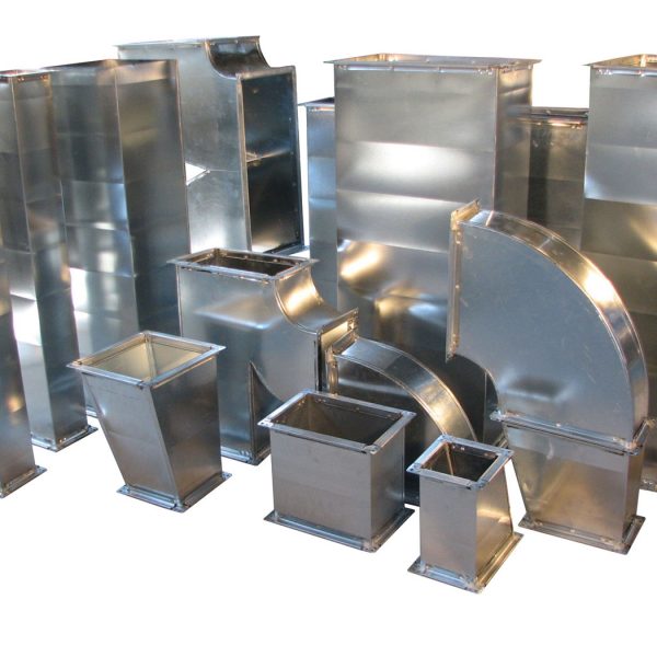
Duct types
First, let's say a few words about the materials and types of ducts.
This is important due to the fact that, depending on the shape of the duct, there are features of its calculation and the choice of cross-sectional area. It is also important to focus on the material, since the features of air movement and the interaction of the flow with the walls depend on it.
In short, air ducts are:
- Metal from galvanized or black steel, stainless steel.
- Flexible from aluminum or plastic film.
- Hard plastic.
- Fabric.
Air ducts are made in shape of round section, rectangular and oval. The most commonly used are round and rectangular pipes.
Most of the air ducts described are factory fabricated, such as flexible plastic or fabric, and are difficult to fabricate on site or in a small workshop. Most of the products that require calculation are made from galvanized steel or stainless steel.
Both rectangular and round air ducts are made of galvanized steel, and the production does not require particularly expensive equipment. In most cases, a bending machine and a device for making round pipes are sufficient. Apart from small hand tools.
Pressure loss
Being in the duct of the ventilation system, the air experiences some resistance.To overcome it, there must be an appropriate level of pressure in the system. It is generally accepted that air pressure is measured in its own units - Pa.
All necessary calculations are carried out using a specialized formula:
P = R * L + Ei * V2 * Y/2,
Here P is pressure; R - partial changes in pressure level; L - total dimensions of the entire duct (length); Ei is the coefficient of all possible losses (summed up); V is the air velocity in the network; Y is the density of air flows.
Get acquainted with all sorts of conventions found in formulas, possibly with the help of special literature (reference books). At the same time, the value of Ei is unique in each individual case due to the dependence on a certain type of ventilation.


An example of calculating ventilation using a calculator
In this example, we will show how to calculate the supply ventilation for a 3-room apartment in which a family of three lives (two adults and a child). During the day, relatives sometimes come to them, so up to 5 people can stay in the living room for a long time. The ceiling height of the apartment is 2.8 meters. Room parameters:
We will set the consumption rates for the bedroom and the nursery in accordance with the recommendations of SNiP - 60 m³ / h per person. For the living room, we will limit ourselves to 30 m³ / h, since a large number of people in this room are infrequent. According to SNiP, such air flow is acceptable for rooms with natural ventilation (you can open a window for ventilation). If we also set an air flow rate of 60 m³/h per person for the living room, then the required performance for this room would be 300 m³/h.The cost of electricity to heat this amount of air would be very high, so we made a compromise between comfort and economy. To calculate the air exchange by the multiplicity for all rooms, we will choose a comfortable double air exchange.
The main air duct will be rectangular rigid, the branches will be flexible and soundproof (this combination of duct types is not the most common, but we chose it for demonstration purposes). For additional cleaning of the supply air, a carbon-dust fine filter of the EU5 class will be installed (we will calculate the network resistance with dirty filters). The air velocities in the air ducts and the permissible noise level on the gratings will be left equal to the recommended values that are set by default.
Let's start the calculation by drawing up a diagram of the air distribution network. This scheme will allow us to determine the length of the ducts and the number of turns that can be both in the horizontal and vertical plane (we need to count all the turns at a right angle). So our schema is:
The resistance of the air distribution network is equal to the resistance of the longest section. This section can be divided into two parts: the main duct and the longest branch. If you have two branches of approximately the same length, then you need to determine which one has more resistance. To do this, we can assume that the resistance of one turn is equal to the resistance of 2.5 meters of the duct, then the branch with the maximum value (2.5 * number of turns + duct length) will have the greatest resistance.It is necessary to select two parts from the route in order to be able to set different types of air ducts and different air speeds for the main section and branches.
In our system, balancing throttle valves are installed on all branches, allowing you to adjust the air flow in each room in accordance with the project. Their resistance (in the open state) has already been taken into account, since this is a standard element of the ventilation system.
The length of the main air duct (from the air intake grille to the branch to room No. 1) is 15 meters, there are 4 right-angle turns in this section. The length of the supply unit and the air filter can be ignored (their resistance will be taken into account separately), and the silencer resistance can be taken equal to the resistance of an air duct of the same length, that is, simply consider it a part of the main air duct. The longest branch is 7 meters long and has 3 right angle bends (one at the branch, one at the duct and one at the adapter). Thus, we have set all the necessary initial data and now we can proceed to the calculations (screenshot). The calculation results are summarized in tables:
Calculation results for rooms
Conclusions and useful video on the topic
Online program to help the design engineer:
The plot of the organization of ventilation of a private house as a whole:
p> Sectional area, shape, length of the duct are some of the parameters that determine the performance of the ventilation system. Correct calculation is extremely important, because. the air throughput, as well as the flow rate and the efficient operation of the structure as a whole, depend on it.
When using an online calculator, the degree of accuracy of the calculation will be higher than when calculating manually. This result is explained by the fact that the program itself automatically rounds the values to more accurate ones.
Do you have personal experience in designing, arranging and calculating an air duct system? Do you want to share your accumulated knowledge or ask questions on a topic? Please leave comments and participate in discussions - the feedback form is located below.


