- CALCULATION OF ELECTRIC HEATING INSTALLATION
- 1.1 Thermal calculation of heating elements
- Adjustment of the heating process
- Design features of gas heat generators
- What types are
- Features of the Antares system
- Volcano or Volcano
- additional literature
- The design of heaters of different types
- Water and steam heaters
- Second option.
- Connection diagram and control
- Efficiency of using heaters instead of heating radiators
- Methods for tying a heater
- Calculation of heater power
- Instructions for calculation with an example
- Calculation of the heating surface
- Features of the calculation of steam heaters
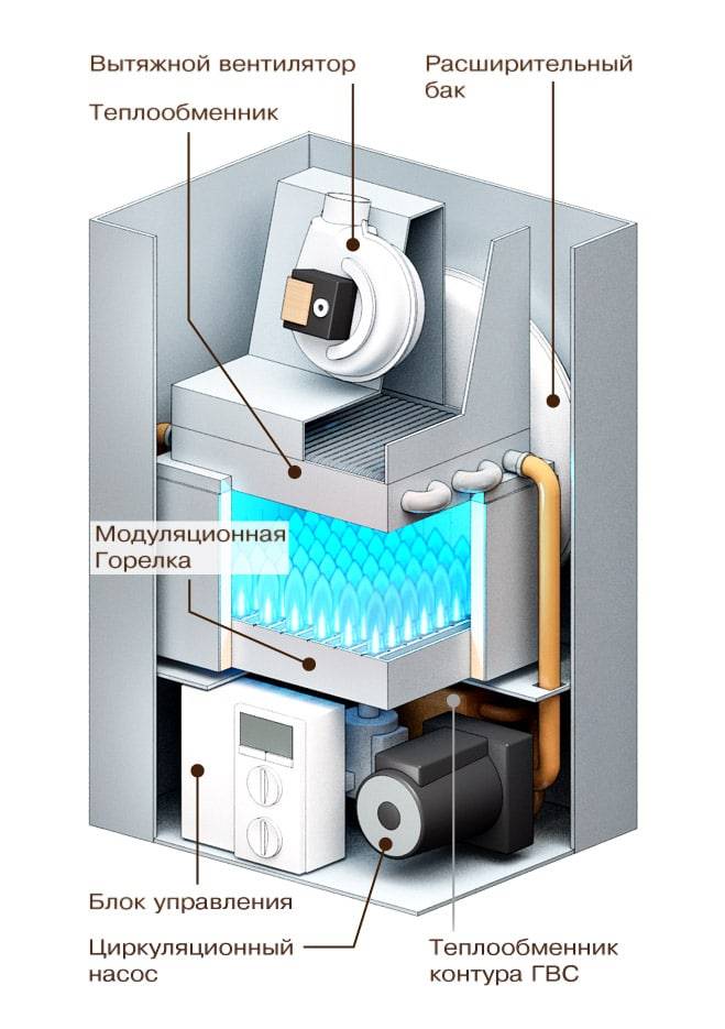
- How does the heating system work?
- Calculation-online of electric heaters. Selection of electric heaters by power - T.S.T.
- Conclusion
CALCULATION OF ELECTRIC HEATING INSTALLATION
|
2
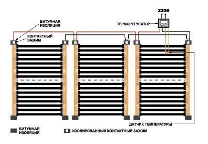
Figure 1.1 - Layout diagrams of the block of heating elements
1.1 Thermal calculation of heating elementsAs heating elements in electric heaters, tubular electric heaters (TEH) are used, mounted in a single structural unit. The task of thermal calculation of the block of heating elements includes determining the number of heating elements in the block and the actual temperature of the surface of the heating element. The results of the thermal calculation are used to refine the design parameters of the block. The task for the calculation is given in Appendix 1. The power of one heating element is determined based on the power of the heater Pto and the number of heating elements z installed in the heater. The number of heating elements z is taken as a multiple of 3, and the power of one heating element should not exceed 3 ... 4 kW. The heating element is selected according to passport data (Appendix 1). According to the design, blocks are distinguished with a corridor and a staggered layout of heating elements (Figure 1.1).
For the first row of heaters of the assembled heating block, the following condition must be met: оС, (1.2) where tn1 - actual average surface temperature of the heaters of the first row, oC; Pm1 is the total power of the heaters of the first row, W; Wed— average heat transfer coefficient, W/(m2оС); Ft1 - total area of the heat-releasing surface of the heaters of the first row, m2; tin - temperature of the air flow after the heater, °C. The total power and the total area of the heaters are determined from the parameters of the selected heating elements according to the formulas where k - the number of heating elements in a row, pcs; Pt, Ft - respectively, power, W, and surface area, m2, of one heating element. Surface area of ribbed heating element where d is the diameter of the heating element, m; la – active length of the heating element, m; hR is the height of the rib, m; a - fin pitch, m For bundles of transversely streamlined pipes, one should take into account the average heat transfer coefficient Wed, since the conditions for heat transfer by separate rows of heaters are different and are determined by the turbulence of the air flow. The heat transfer of the first and second rows of tubes is less than that of the third row. If the heat transfer of the third row of heating elements is taken as unity, then the heat transfer of the first row will be about 0.6, the second - about 0.7 in staggered bundles and about 0.9 - in the in-line from the heat transfer of the third row. For all rows after the third row, the heat transfer coefficient can be considered unchanged and equal to the heat transfer of the third row. The heat transfer coefficient of the heating element is determined by the empirical expression , (1.5) where Nu – Nusselt criterion, - coefficient of thermal conductivity of air, = 0.027 W/(moC); d – diameter of the heating element, m. The Nusselt criterion for specific heat transfer conditions is calculated from the expressions for in-line tube bundles at Re 1103 , (1.6) at Re > 1103 , (1.7) for staggered tube bundles: for Re 1103, (1.8) at Re > 1103 , (1.9) where Re is the Reynolds criterion. The Reynolds criterion characterizes the air flow around the heating elements and is equal to where — air flow velocity, m/s; — coefficient of kinematic viscosity of air, = 18.510-6 m2/s. In order to ensure an effective thermal load of heating elements that does not lead to overheating of the heaters, it is necessary to ensure air flow in the heat exchange zone at a speed of at least 6 m/s. Taking into account the increase in the aerodynamic resistance of the air duct structure and the heating block with an increase in the air flow velocity, the latter should be limited to 15 m/s. Average heat transfer coefficient for in-line bundles for chess beams , (1.12) where n — the number of rows of pipes in the bundle of the heating block. The temperature of the air flow after the heater is where Pto – total power of heating elements heater, kW; — air density, kg/m3; Within is the specific heat capacity of air, Within= 1 kJ/(kgоС); Lv – air heater capacity, m3/s. If condition (1.2) is not met, choose another heating element or change the air velocity taken in the calculation, the layout of the heating block. Table 1.1 - values of the coefficient c Initial dataShare with your friends: |
2
Adjustment of the heating process
There are two ways to adjust the operating mode:
- Quantitative. Adjustment is made by changing the volume of coolant entering the device. With this method, there are sharp jumps in temperature, instability of the regime, therefore, the second type has recently been more common.
- Qualitative. This method allows you to ensure a constant flow of coolant, which makes the operation of the device more stable and smooth. At a constant flow rate, only the temperature of the carrier changes. This is done by mixing a certain amount of colder return into the forward flow, which is controlled by a three-way valve. Such a system protects the structure from freezing.
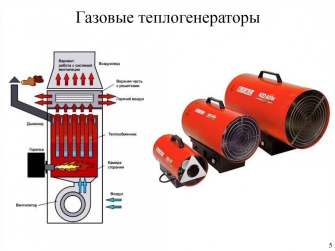
Design features of gas heat generators
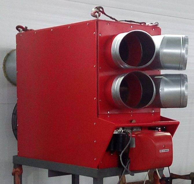
Air heating is most effective in exhibition halls, industrial premises, film studios, car washes, poultry farms, workshops, large private houses, etc.
Standard gas heat generator for the operation of air heating consists of several parts that interact with each other:
- Frame. It contains all the components of the generator. In its lower part there is an inlet, and at the top there is a nozzle for already heated air.
- The combustion chamber.Here, fuel is burned, due to which the coolant is heated. It is located above the supply fan.
- Burner. The device provides compressed oxygen supply to the combustion chamber. Thanks to this, the combustion process is supported.
- Fan. It distributes heated air around the room. It is located behind the air inlet grille in the lower part of the housing.
- Metal heat exchanger. A compartment from which heated air is supplied to the outside. It is located above the combustion chamber.
- Hoods and filters. Limit the entry of combustible gases into the room.
Air is supplied to the case by means of a fan. The vacuum is generated in the area of the supply grate.
The air heating device costs 3-4 times cheaper than the "water" scheme. In addition, air options are not threatened with loss of thermal energy during transportation due to hydraulic resistance.
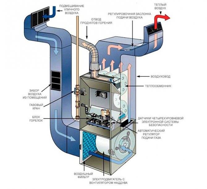
The pressure is concentrated opposite the combustion chamber. By oxidizing liquefied or natural gas, the burner generates heat.
The energy from the combustion gas is absorbed by a metal heat exchanger. As a result, the air circulation in the case becomes difficult, its speed is lost, but the temperature rises.
Knowing the power of the heating element, you can calculate the size of the hole that will provide the necessary air flow
Without a heat exchanger, much of the energy from the combustion gas would be wasted and the burner would be less efficient.
Such heat exchange heats the air to 40-60°C, after which it is fed into the room through a nozzle or bell, which are provided in the upper part of the housing.
Fuel is supplied to the combustion chamber, where a heat exchanger is heated during combustion, transferring thermal energy to the coolant
The environmental friendliness of the equipment, as well as its safety, make it possible to use heat generators in everyday life. Another advantage is the absence of liquid moving through pipes to convectors (batteries). The heat generated heats the air, not the water. Thanks to this, the efficiency of the device reaches 95%.
What types are
There are two ways to circulate air in the system: natural and forced. The difference is that in the first case, the heated air moves in accordance with the laws of physics, and in the second case, with the help of fans. According to the method of air exchange, the devices are divided into:
- recirculation - use air directly from the room;
- partially recirculating - partially use the air from the room;
- supply air, using air from the street.
Features of the Antares system
The principle of operation of Antares comfort is the same as that of other air heating systems.
The air is heated by the AVH unit and is distributed through the air ducts with the help of fans throughout the premises.
The air returns back through the return ducts, passing through the filter and the collector.
The process is cyclic and goes on endlessly. Mixing with warm air from the house in the heat exchanger, the entire flow goes through the return duct.
Advantages:
- Low noise level. It's all about the modern German fan. The structure of its backward curved blades pushes the air slightly. He does not hit the fan, but as if enveloping. In addition, thick sound insulation AVN is provided. The combination of these factors makes the system almost silent.
- Room heating rate.The fan speed is adjustable, which makes it possible to set the full power and quickly warm the air to the desired temperature. The noise level will rise noticeably in proportion to the speed of the supplied air.
- Versatility. In the presence of hot water, the Antares comfort system is able to work with any type of heater. It is possible to install both water and electric heaters at the same time. This is very convenient: when one power source fails, switch to another.
- Another feature is modularity. This means that Antares comfort is made up of several blocks, which results in weight reduction and ease of installation and maintenance.
With all the advantages, Antares comfort has no drawbacks.
Volcano or Volcano
A water heater and a fan connected together - this is how the heating units of the Polish company Volkano look like. They work from indoor air and do not use outdoor air.
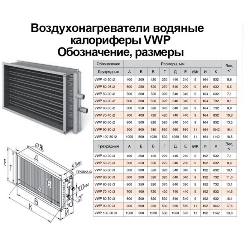
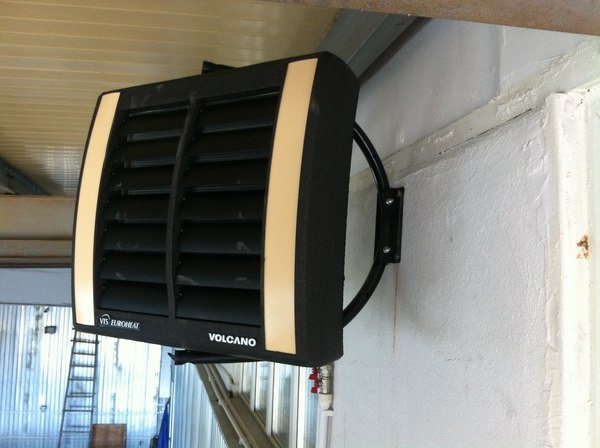
Photo 2. Device from the manufacturer Volcano designed for air heating systems.
The air heated by the thermal fan is evenly distributed through the provided shutters in four directions. Special sensors maintain the desired temperature in the house. Shutdown occurs automatically when the unit is not needed. There are several models of Volkano thermal fans in different sizes on the market.
Peculiarities air heating units Volkano:
- quality;
- affordable price;
- noiselessness;
- possibility of installation in any position;
- housing made of wear-resistant polymer;
- complete readiness for installation;
- three years warranty;
- economy.
Perfect for heating factory floors, warehouses, large shops and supermarkets, poultry farms, hospitals and pharmacies, sports centers, greenhouses, garage complexes and churches. Wiring diagrams are included to make installation quick and easy.
additional literature
- “Application of I-d diagrams for calculations” of the reference book “Internal sanitary devices. Part 3. Ventilation and air conditioning. Book 1. M .: "Stroyizdat", 1991. Air preparation.
- Ed. I.G. Staroverova, Yu.I. Schiller, N.N. Pavlov and others. "Designer's Handbook" Ed. 4th, Moscow, Stroyizdat, 1990
- Ananiev V.A., Balueva L.N., Galperin A.D., Gorodov A.K., Eremin M.Yu., Zvyagintseva S.M., Murashko V.P., Sedykh I.V. “Ventilation and air conditioning systems. Theory and practice." Moscow, Euroclimate, 2000
- Becker A. (translation from German Kazantseva L.N., edited by Reznikov G.V.) "Ventilation Systems" Moscow, Euroclimate, 2005
- Burtsev S.I., Tsvetkov Yu.N. "Wet air. Composition and properties. Tutorial." St. Petersburg, 1998
- Flaktwoods technical catalogs
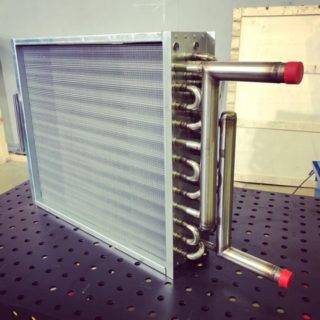
The design of heaters of different types
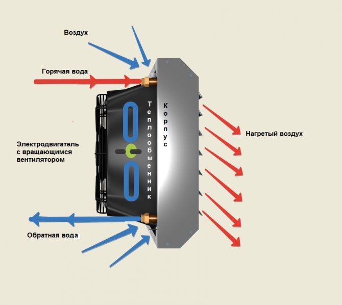
A heater is a heat exchanger that transfers the energy of the coolant to the air heating flow and works on the principle of a hair dryer. Its design includes removable side shields and heat transfer elements. They can be connected in one or more lines. The built-in fan provides air draft, and the air mass enters the room through the gaps that exist between the elements. When air from the street passes through them, heat is transferred to it. The heater is installed in the ventilation duct, so the device must match the mine in size and shape.
Water and steam heaters
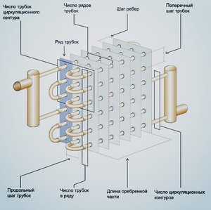
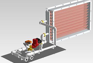
Water and steam heaters can be of two types: ribbed and smooth tube. The first, in turn, are further divided into two types: lamellar and spiral-wound. The design can be single-pass or multi-pass. In multi-pass devices there are partitions, due to which the direction of flow changes. The tubes are arranged in 1-4 rows.
A water heater consists of a metal, often rectangular frame, inside which are placed rows of tubes and a fan. The connection is made to the boiler or CSO with the help of outlet pipes. The fan is located on the inside, it pumps air into the heat exchanger. 2-way or 3-way valves are used to control power and outlet air temperature. Devices are installed on the ceiling or on the wall.
There are three types of water and steam heaters.
Smooth-tube. The design consists of hollow tubes (diameter from 2 to 3.2 cm) located at small intervals (about 0.5 cm). They can be made of steel, copper, aluminum. The ends of the tubes communicate with the collector. A heated coolant enters the inlets, and condensate or cooled water enters the outlet. Smooth-tube models are less productive than others.
Usage features:
- minimum inlet temperature -20°C;
- requirements for air purity - no more than 0.5 mg / m3 in terms of dust content.
Ribbed. Due to the finned elements, the heat transfer area increases, therefore, other things being equal, finned heaters are more productive than smooth-tube ones. Plate models are distinguished by the fact that plates are mounted on the tubes, which further increase the heat transfer surface area.Corrugated steel tape is wound in windings.
Bimetallic with fins. The greatest efficiency can be achieved through the use of two metals: copper and aluminum. Collectors and branch pipes are made of copper, and fins are made of aluminum. Moreover, a special type of finning is performed - spiral-rolling.
Second option.
(See Figure 4).
Absolute air humidity or moisture content of the outside air - dH"B", less than the moisture content of the supply air - dP
dH „B“ P g/kg.
1. In this case, it is necessary to cool the outside supply air - (•) H on the J-d diagram, to the temperature of the supply air.
The process of air cooling in a surface air cooler on the J-d diagram will be represented by a straight line BUT. The process will occur with a decrease in heat content - enthalpy, a decrease in temperature and an increase in the relative humidity of the external supply air. At the same time, the moisture content of the air remains unchanged.
2. In order to get from the point - (•) O, with the parameters of cooled air to the point - (•) P, with the parameters of the supply air, it is necessary to humidify the air with steam.
At the same time, the air temperature remains unchanged - t = const, and the process on the J-d diagram will be depicted by a straight line - an isotherm.
Schematic diagram of the supply air treatment in the warm season - TP, for the 2nd option, case a, see Figure 5.
(See Figure 6).
Absolute air humidity or moisture content of the outside air - dH"B", more than the moisture content of the supply air - dP
dH"B" > dP g/kg.
1. In this case, it is necessary to “deeply” cool the supply air. i.e.the process of air cooling on the J - d diagram will initially be depicted by a straight line with constant moisture content - dH = const, drawn from a point with outdoor air parameters - (•) H, until it intersects with the line of relative humidity - φ = 100%. The resulting point is called - dew point - T.R. outside air.
2. Further, the cooling process from the dew point will go along the line of relative humidity φ \u003d 100% to the final cooling point - (•) O. The numerical value of the air moisture content from the point (•) O is equal to the numerical value of the air moisture content at the inflow point - (•) P .
3. Next, it is necessary to heat the air from the point - (•) O, to the point of supply air - (•) P. The process of heating the air will occur with a constant moisture content.
Schematic diagram of the supply air treatment in the warm season - TP, for the 2nd option, case b, see Figure 7.
Connection diagram and control
Connection of electric heaters must be carried out in compliance with all safety requirements. The connection diagram of the electric heater is as follows: when the “Start” button is pressed, the engine starts and the heater ventilation turns on. At the same time, the engine is equipped with a thermal relay, which, in case of problems with the fan, instantly opens the circuit and turns off the electric heater. It is possible to turn on the heating elements separately from the fan by closing the blocking contacts. To ensure the fastest heating, all heating elements turn on simultaneously.
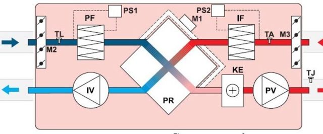

To improve the safety of the electric heater, the connection diagram includes an emergency indicator and a device that does not allow the heating elements to be turned on when the fan is off.In addition, experts recommend the inclusion of automatic fuses in the circuit, which should be placed in the circuit along with heating elements. But on the fans, the installation of automatic machines, on the contrary, is not recommended. The heater is controlled from a special cabinet located near the device. Moreover, the closer it is located, the smaller the cross section of the wire connecting them can be.
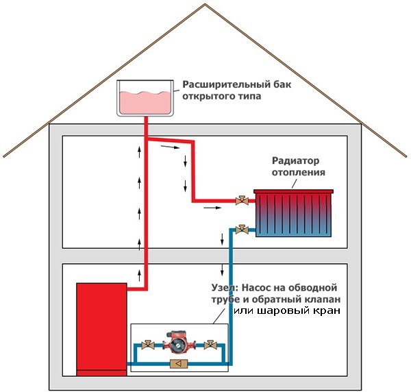
When choosing a water heater connection scheme, it is necessary to focus on the placement of mixing units and blocks with automation. So, if these units are located to the left of the air valve, then left-hand execution is implied, and vice versa. In each version, the arrangement of the connecting pipes corresponds to the air intake side with the damper installed.
There are a number of differences between left and right placement. So, with the right version, the water supply tube is located at the bottom, and the “return” tube is at the top. In left-handed schemes, the supply pipe enters from above, and the outflow pipe is at the bottom.
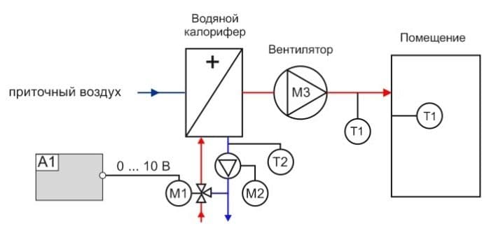
When installing the heater, it is required to equip the piping unit necessary to monitor the performance of the device and protect it from freezing. Strapping nodes are called reinforcing cages that regulate the flow of hot water into the heat exchanger. The piping of water heaters is carried out using two- or three-way valves, the choice of which depends on the type of heating system. So, in circuits heated with a gas boiler, it is recommended to install a three-way model, while for systems with central heating, a two-way model is sufficient.

The control of the water heater consists in the regulation of the thermal power of the heating devices. This is made possible by the process of mixing hot and cold water, which is carried out using a three-way valve. When the temperature rises above the set value, the valve launches a small portion of the cooled liquid into the heat exchanger, taken at the exit from it.
In addition, the scheme for installing water heaters does not provide for a vertical arrangement of the inlet and outlet pipes, as well as the location of the air intake from above. Such requirements are due to the risk of snow getting into the air duct and melt water flowing into the automation. An important element of the connection diagram is the temperature sensor. To obtain correct readings, the sensor must be placed inside the duct in the blowing section, and the length of the flat section must be at least 50 cm.
Efficiency of using heaters instead of heating radiators
The coolant circulating through the radiators of water heating transfers thermal energy to the surrounding air by thermal radiation, as well as through the movement of convection currents of heated air upwards, the flow of cooled air from below.
The heater, in addition to these two passive methods of transferring thermal energy, drives air through a system of heated elements with a much larger area and intensively transfers heat to them. Evaluate the efficiency of heaters and fans to allow a simple calculation of the cost of installed equipment for the same tasks.
An example of heating a car maintenance service room with heaters.
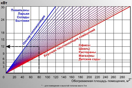
For example, it is necessary to compare the cost of radiators and heaters for heating the showroom of a car dealership, taking into account the implementation of SNIP standards.
The heating main is the same, the coolant is of the same temperature, the piping and installation can be ignored in a simplified calculation of the costs of the main equipment. For a simple calculation, we take the known rate of 1 kW per 10 m2 of heated area. A hall with an area of 50x20 = 1000 m2 requires a minimum of 1000/10 = 100 kW. Taking into account a margin of 15%, the estimated minimum required heating output of heating equipment is 115 kW.
When using radiators. We take one of the most common bimetallic radiators Rifar Base 500 x10 (10 sections), one such panel produces 2.04 kW. The minimum required number of radiators will be 115/2.04 = 57 pcs. It should immediately be taken into account that it is unreasonable and almost impossible to place 57 radiators in such a room. With the price of a device for 10 sections of 7,000 rubles, the cost of purchasing radiators will be 57 * 7000 = 399,000 rubles.
When heating with heaters. For heating a rectangular area in order to evenly distribute heat, we make a selection of 5 Ballu BHP-W3-20-S water heaters with a capacity of 3200 m3 / h each with a close total power: 25 * 5 = 125 kW. Equipment costs will be 22900 * 5 = 114,500 rubles.
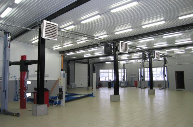
The main scope of heaters is the organization of heating of premises with large spaces for air movement:
- production shops, hangars, warehouses;
- sports halls, exhibition pavilions, shopping malls;
- agricultural farms, greenhouses.
A compact device that allows you to quickly heat the air from 70°C to 100°C, easily integrated into the general automatic heating control system, it is advisable to use in facilities with reliable access to the coolant (water, steam, electricity).
The advantages of water heaters are:
- High profitability of use (low cost of equipment, high heat transfer, ease and low cost of installation, minimum operating costs).
- Rapid heating of air, ease of change and localization of heat flow (thermal curtains and oases).
- Robust design, easy automation and modern design.
- Safe to use even in high-risk buildings.
- Extremely compact dimensions with high heat output.
The disadvantages of these devices are associated with the properties of the coolant:
- At temperatures below zero, the heater is easy to freeze. Water from the pipes not drained in time can break them if disconnected from the main.
- When using water with a large amount of impurities, it is also possible to disable the device, so using it in everyday life without filters and connecting to a central system is not advisable.
- It is worth noting that heaters dry the air a lot. When used, for example, in a showroom, humidification climate technology is required.
Methods for tying a heater
The piping of the fresh air heater is performed in several ways. The location of the nodes is directly related to the installation site, technical characteristics and the air exchange scheme used. The most commonly used option, which provides for the mixing of the air removed from the room with the incoming air masses.Closed models are less commonly used, in which air is recirculated only within one room without mixing with air masses coming from the street.
If the operation of natural ventilation is well established, then in this case it is advisable to install a supply model with a water-type heater. It is connected to the heating system at the air intake point, most often located in the basement. If there is forced ventilation, then heating equipment is installed anywhere.
On sale you can find ready-made strapping knots. They differ in execution options.
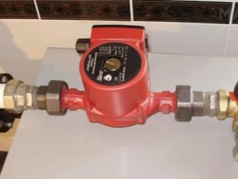
The kit includes:
- pump equipment;
- check valve;
- cleaning filter;
- balancing valve;
- two- or three-way valve mechanisms;
- Ball Valves;
- bypasses;
- pressure gauges.
Depending on the connection conditions, one of the strapping options is used:
- Flexible harness is mounted on control nodes, which are located near the device. This installation option is simpler, since threaded connections are used to assemble all parts. Thanks to this, welding equipment is not needed.
- Rigid strapping is used if the control nodes are far from the device. In this case, it is necessary to lay strong communications with rigid welded joints.
Calculation of heater power

Let's determine the initial data that will be needed to correctly select the power of the heater for ventilation:
- The volume of air that will be distilled per hour (m3/h), i.e. the performance of the whole system is L.
- Temperature outside the window. – tst.
- The temperature to which it is necessary to bring the heating of the air - tcon.
- Tabular data (density of air of a certain temperature, heat capacity of air of a certain temperature).
Instructions for calculation with an example
Step 1. Air flow by mass (G in kg/h).


Formula: G = LxP
Where:
- L - air flow by volume (m3/h)
- P is the average air density.
Example: -5 ° С air enters from the street, and t + 21 ° С is needed at the outlet.
Sum of temperatures (-5) + 21 = 16
Average value 16:2 = 8.
The table determines the density of this air: P = 1.26.
| Air density depending on temperature kg/m3 | ||||||||||||||||||||||||||
| -50 | -45 | -40 | -35 | -30 | -25 | -20 | -15 | 10- | -5 | +5 | +10 | +15 | +20 | +25 | +30 | +35 | +40 | +45 | +50 | +60 | +65 | +70 | +75 | +80 | +85 | |
| 1,58 | 1,55 | 1,51 | 1,48 | 1,45 | 1,42 | 1,39 | 1,37 | 1,34 | 1,32 | 1,29 | 1,27 | 1,25 | 1,23 | 1,20 | 1,18 | 1,16 | 1,15 | 1,13 | 1,11 | 1,09 | 1,06 | 1,04 | 1,03 | 1,01 | 1,0 | 0,99 |
If the ventilation capacity is 1500 m3 / h, then the calculations will be as follows:
G \u003d 1500 x 1.26 \u003d 1890 kg / h.
Step 2. Heat consumption (Q in W).
Formula: Q = GxС x (tcon – tst)
Where:
- G is the air flow by mass;
- C - specific heat capacity of the air entering from the street (table indicator);
- tcon is the temperature to which the flow must be heated;
- tst - the temperature of the flow entering from the street.
Example:
According to the table, we determine C for air, with a temperature of -5 ° C. This is 1006.
| Heat capacity of air depending on temperature, J/(kg*K) | ||||||||||||||||||||||||||
| -50 | -45 | -40 | -35 | -30 | -25 | -20 | -15 | 10- | -5 | +5 | +10 | +15 | +20 | +25 | +30 | +35 | +40 | +45 | +50 | +60 | +65 | +70 | +75 | +80 | +85 | |
| 1013 | 1012 | 1011 | 1010 | 1010 | 1009 | 1008 | 1007 | 1007 | 1006 | 1005 | 1005 | 1005 | 1005 | 1005 | 1005 | 1005 | 1005 | 1005 | 1005 | 1005 | 1005 | 1006 | 1006 | 1007 | 1007 | 1008 |
We substitute the data in the formula:
Q \u003d (1890/3600 *) x 1006 x (21 - (-5)) \u003d 13731.9 ** W
*3600 is the hour converted to seconds.
**The resulting data are rounded up.
Result: for air heating from -5 to 21 °C in a system with a capacity of 1500 m3, a 14 kW heater is required
There are online calculators where, by entering performance and temperatures, you can get an approximate power indicator.
It is better to provide a power margin (5-15%), since the performance of equipment often decreases over time.
Calculation of the heating surface
To calculate the heated surface area (m2) of a ventilation heater, use the following formula:
S = 1.2 Q : (k (tJew. – t air.)
 Where:
- 1.2 - cooling coefficient;
- Q is the heat consumption, which we have already calculated earlier;
- k is the heat transfer coefficient;
- tJew. - the average temperature of the coolant in the pipes;
- tair - the average temperature of the flow coming from the street.
K (heat transfer) is a tabular indicator.
Average temperatures are calculated by finding the sum of the incoming and the desired temperature, which must be divided by 2.
The result is rounded up.
Knowing the surface area of the heater for ventilation may be needed when selection of the necessary equipment, as well as for the purchase of the required amount of materials for the independent manufacture of system elements.
Features of the calculation of steam heaters
As already mentioned, the heaters are used the same for water heating and for the use of steam. Calculations are carried out according to the same formulas, only the coolant flow rate is calculated by the formula:
G=Q:m
Where:
- Q - heat consumption;
- m is an indicator of the heat released during the condensation of steam.
And the speed of movement of steam through the pipes is not taken into account.
How does the heating system work?
The fan blades capture air and direct it to the heat exchanger. The air stream heated by it circulates through the building, performing several cycles.
The main advantage of the gas heat generator design is that the location of the chambers and compartments prevents the spent fuel decay products from mixing with the air from the room.
During the operation of the equipment, you do not need to be afraid that the pipe will burst and you will flood your neighbors, as is often the case with water heating systems. However, in the heat-generating device itself, sensors are provided that, in emergency situations (threat of breakage), stop the fuel supply.
Heated air is supplied to the room in several ways:
- Channelless. Warm air enters freely into the treated space. During circulation, it replaces the cold one, which allows you to maintain the temperature regime. The use of heating of this type is advisable in small rooms.
- Channel. Through a system of interconnected air ducts, the heated air moves through the air ducts, which makes it possible to heat several rooms at the same time. It is used for heating large buildings with separate rooms.
Stimulates the movement of air mass fan or gravity forces. The heat generator can be installed indoors and outdoors.
The use of air as a heat carrier makes the system as profitable as possible. The air mass does not cause corrosion, and is also not capable of damaging any elements of the system.
In order for the heating system to function correctly, the chimney must be correctly connected to the gas heat generator.
If the flue is installed incorrectly, it will be more likely to become clogged with soot buildup. A narrowed and clogged chimney will not remove toxic substances well.
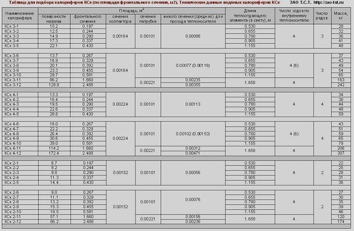
Calculation-online of electric heaters. Selection of electric heaters by power - T.S.T.
Skip to content This page of the site presents an online calculation of electric heaters.The following data can be determined online: - 1. the required output (heat output) of the electric air heater for the air handling unit. Basic parameters for calculation: volume (flow rate, performance) of the heated air flow, air temperature at the inlet to the electric heater, desired outlet temperature - 2. air temperature at the outlet of the electric heater. Basic parameters for calculation: consumption (volume) of the heated air flow, air temperature at the inlet to the electric heater, actual (installed) thermal power of the electrical module used
1. Online calculation of the power of the electric heater (heat consumption for heating the supply air)
The following indicators are entered into the fields: the volume of cold air passing through the electric heater (m3/h), the temperature of the incoming air, the required temperature at the outlet of the electric heater. At the output (according to the results of the online calculation of the calculator), the required power of the electric heating module is displayed to comply with the set conditions.
1 field. The volume of supply air passing through the electric heater (m3/h)2 field. Air temperature at the inlet to the electric heater (°С)
3 field. Required air temperature at the outlet of the electric heater
(°C) field (result). Required power of the electric heater (heat consumption for supply air heating) for the entered data
2. Online calculation of the air temperature at the outlet of the electric heater
The following indicators are entered into the fields: the volume (flow) of heated air (m3/h), the air temperature at the inlet to the electric heater, the power of the selected electric air heater.At the outlet (according to the results of the online calculation), the temperature of the outgoing heated air is displayed.
1 field. The volume of supply air passing through the heater (m3/h)2 field. Air temperature at the inlet to the electric heater (°С)
3 field. Thermal power of the selected air heater
(kW) field (result). Air temperature at the outlet of the electric heater (°С)
Online selection of an electric heater by the volume of heated air and heat output
Below is a table with the nomenclature of electric heaters produced by our company. According to the table, you can roughly select the electrical module suitable for your data. Initially, focusing on the indicators of the volume of heated air per hour (air productivity), you can choose an industrial electric heater for the most common thermal conditions. For each heating module of the SFO series, the most acceptable (for this model and number) range of heated air is presented, as well as some ranges of air temperature at the inlet and outlet of the heater. By clicking on the name of the selected electric air heater, you can go to the page with the thermal characteristics of this electric industrial air heater.
| Name of electric heater | Installed power, kW | Air performance range, m³/h | Inlet air temperature, °С | Outlet air temperature range, °C (depending on air volume) |
| SFO-16 | 15 | 800 — 1500 | -25 | +22 0 |
| -20 | +28 +6 | |||
| -15 | +34 +11 | |||
| -10 | +40 +17 | |||
| -5 | +46 +22 | |||
| +52 +28 | ||||
| SFO-25 | 22.5 | 1500 — 2300 | -25 | +13 0 |
| -20 | +18 +5 | |||
| -15 | +24 +11 | |||
| -10 | +30 +16 | |||
| -5 | +36 +22 | |||
| +41 +27 | ||||
| SFO-40 | 45 | 2300 — 3500 | -30 | +18 +2 |
| -25 | +24 +7 | |||
| -20 | +30 +13 | |||
| -10 | +42 +24 | |||
| -5 | +48 +30 | |||
| +54 +35 | ||||
| SFO-60 | 67.5 | 3500 — 5000 | -30 | +17 +3 |
| -25 | +23 +9 | |||
| -20 | +29 +15 | |||
| -15 | +35 +20 | |||
| -10 | +41 +26 | |||
| -5 | +47 +32 | |||
| SFO-100 | 90 | 5000 — 8000 | -25 | +20 +3 |
| -20 | +26 +9 | |||
| -15 | +32 +14 | |||
| -10 | +38 +20 | |||
| -5 | +44 +25 | |||
| +50 +31 | ||||
| SFO-160 | 157.5 | 8000 — 12000 | -30 | +18 +2 |
| -25 | +24 +8 | |||
| -20 | +30 +14 | |||
| -15 | +36 +19 | |||
| -10 | +42 +25 | |||
| -5 | +48 +31 | |||
| SFO-250 | 247.5 | 12000 — 20000 | -30 | +21 0 |
| -25 | +27 +6 | |||
| -20 | +33 +12 | |||
| -15 | +39 +17 | |||
| -10 | +45 +23 | |||
| -5 | +51 +29 |
Conclusion
A water heater in the ventilation system is economical, especially in a system with central heating.In addition to the functions of air heating, it can perform the functions of an air conditioner in the summer. It is only necessary to choose the right device for power and surface area, as well as correctly connect and tie.
Do you know that air ions must be present in the atmosphere where a person is located? In apartments, as a rule, ions are not enough. However, some people believe that it is harmful to artificially enrich the air with them. You will find the answer to this question on our website.
Read the instructions for assembling a homemade steam generator in the material.