- Types of electromagnetic relays
- According to electrical parameters
- By execution
- TYPES OF INTERMEDIATE RELAYS
- Types of thermal protection relays
- Application area
- Relay contacts.
- 3.1. Normally open contacts.
- 3.2. Normally closed contacts.
- 3.3. Changeover contacts.
- Types of intermediate relays
- Device types
- Characteristics of solid state relay
- Comments
- Several types of connection schemes
- Relay marking
- Schematic diagrams
- Wiring diagram
- Block diagrams
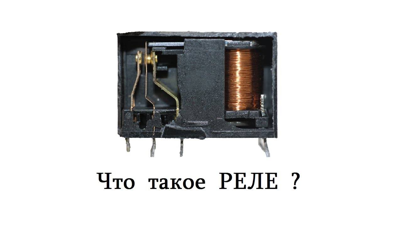
- Relay principles
- Types of electrical circuits
- Leading relay manufacturers
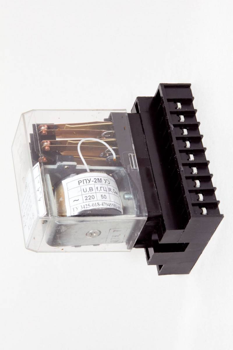
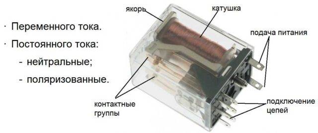
Types of electromagnetic relays
The first classification is nutritional. There are electromagnetic relay of direct and alternating current. DC relays can be neutral or polarized. Neutral ones work when power is supplied of any polarity, polarized ones react only to positive or negative (depending on the direction of the current).
Types of electromagnetic relays by type of supply voltage and the appearance of one of the models
According to electrical parameters
Electromagnetic relays are also divided by sensitivity:
- Power to operate 0.01 W or less - highly sensitive.
- The power consumed by the winding during operation is from 0.01 W to 0.05 W - sensitive.
- The rest are normal.
First of all, it is worth deciding on the electrical parameters
The first two groups (highly sensitive and sensitive) can be controlled from microcircuits. They may well produce the required voltage level, so intermediate amplification is not required.
According to the level of switched load, there is such a division:
- No more than 120 W AC and 60 W DC - low current.
- 500 W AC and 150 W DC - high power;
- More than 500 W AC - contactors. Used in power circuits.
There is also a division according to the response time. If the contacts close no more than 50ms (milliseconds) after the coil is energized, it is fast acting. If it takes from 50 ms to 150 ms, this is normal speed, and all that require more than 150 ms to operate contacts are slow.
By execution
There are also electromagnetic relays with varying degrees of tightness.
- Open electromagnetic relays. These are those in which all the parts are "in sight".
- Sealed. They are soldered or welded into a metal or plastic case, inside which is air or an inert gas. There is no access to the contacts and the coil, only the terminals for supplying power and connecting circuits are available.
- Sheathed. There is a cover, but it is not soldered, but is connected to the body with latches. Sometimes there is a slip-on wire loop that holds the lid.
In terms of weight and size, the differences can be very significant.
And another principle of division is by size. There are microminiature ones - they weigh less than 6 grams, miniature ones - from 6 to 16 grams, small-sized ones have a mass of 16 grams to 40 grams, and the rest are normal.
TYPES OF INTERMEDIATE RELAYS
The protection and automation circuits are powered from special operating current circuits. By type, the operating current can be AC or DC.
Batteries, capacitor banks or rectifiers can serve as sources of voltage for direct operational current; the busbars of the variable op-current are powered by voltage from auxiliary transformers.
Since intermediate relays work in the control voltage circuits, depending on its type, they are produced with coils for direct and alternating current.
RP - 23.
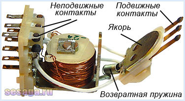
This type of intermediate relay is designed for operation in DC voltage circuits. RP - 23 consists of a voltage coil with a magnetic core. The moving part of the magnetic system is the armature, which, when voltage is applied to the coil, is attracted to the core.
A traverse is mechanically connected to the anchor, on which four contact bridges are fixed. Attracted to the core, the anchor lowers the traverse, compressing the spring on which it is installed. In this case, the normally open contacts are closed and the normally closed contacts are opened.
Fixed contacts RP - 23 are made in the form of corners from thin copper plates. Each of the corners can be installed in one of two ways. Thanks to this, four types of combinations of options for contact groups can be obtained (p - opening group, z - closing group):
- 1 p, 4 h;
- 2 p, 3 h;
- 3 p, 2 h;
- 4 p, 1 z.
This invariance makes it possible to adapt this device to work as part of any circuit.
When opened, two air gaps are created for each contact, thereby increasing their arcing capacity.
This property is important when the relay device operates in the trip circuits of high-voltage switches, the solenoids of which have a large inductance and maintain the voltage of the electric arc when the circuit is broken. RP - 23 is available in various modifications for operation in operational circuits with a voltage of 24 V, 48 V, 110 V and 220 V
RP - 23 is produced in various modifications for operation in operational circuits with a voltage of 24 V, 48 V, 110 V and 220 V.
RP - 25.
The internal wiring diagram of this type of intermediate relay is similar to RP - 23. The RP - 25 coil is designed to operate on alternating voltage. The versions are equipped with 100 V, 127 V or 220 V coils.


The working life of the electromagnetic mechanism of the intermediate relays RP - 23 and RP - 25 is 100,000 operations. The contact group withstands 10,000 cycles of closing - opening with a full electrical load in terms of current and voltage.
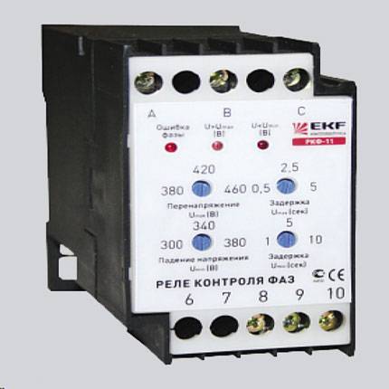
Types of thermal protection relays
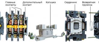
There are several types of relays for electric motor protection against phase failure and current overloads. All of them differ in design features, the type of MP used and the use in different motors.
TRP. Single-pole switching device with combined heating system. Designed to protect asynchronous three-phase electric motors from current overloads. TRP is used in DC power networks with a base voltage of no more than 440 V under normal operation conditions. It is resistant to vibrations and shocks.
RTL. Provide motor protection in such cases:
- when one of the three phases falls out;
- asymmetry of currents and overloads;
- delayed start;
- jamming of the actuator.
They can be installed with KRL terminals separately from magnetic starters or mounted directly on the PML. Mounted on rails of a standard type, protection class - IP20.
RTT. They protect asynchronous three-phase machines with a squirrel-cage rotor from a prolonged start of the mechanism, prolonged overloads and asymmetry, that is, phase imbalance.
PTTs can be used as components in various electric drive control circuits, as well as for integration into PMA series starters
TRN. Two-phase switches that control the start-up of the electrical installation and the mode of operation of the motor. They practically do not depend on the ambient temperature, they have only a system for manually returning contacts to their initial state. They can be used in DC networks.
RTI. Electrical switching devices with constant, albeit low, power consumption. Mounted on KMI series contactors. Operates in conjunction with fuses/circuit breakers.
Solid state current relays. They are small electronic devices for three phases, in the design of which there are no moving parts.
They function on the principle of calculating the average values of motor temperatures, for this purpose they constantly monitor the operating and starting current. They are immune to changes in the environment, and therefore are used in explosive areas.
RTK. Starting switches for temperature control in the electrical enclosure. They are used in automation circuits, where thermal relays act as components.
To ensure reliable operation of electrical equipment, the relay element must have such qualities as sensitivity and speed, as well as selectivity
It is important to remember that none of the above devices is suitable for protecting circuits from short circuits. Thermal protection devices only prevent emergency modes that occur during abnormal operation of the mechanism or overload
Thermal protection devices only prevent emergency modes that occur during abnormal operation of the mechanism or overload.
Electrical equipment can burn out even before the relay starts to operate. For comprehensive protection, they must be supplemented with fuses or modular compact circuit breakers.
Application area
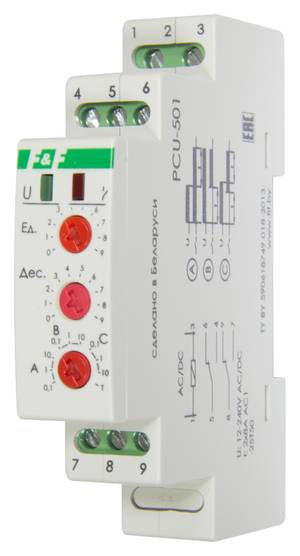
Intermediate relay in the electrical panel
RP is found in almost all power, control and protection schemes. Switching devices are used in substations, control rooms, boiler rooms. On the production line, the device can perform both simultaneously and sequentially several switching in control or power circuits. RP is widely used for computer technology, telecommunications, controls and other electronic devices.
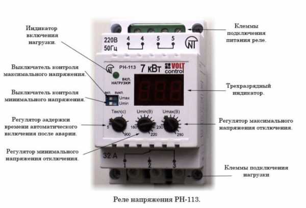
In water supply and heating systems, when the deep pump is turned on, power is supplied to the coil. When the contacts are closed, the control system starts to work. The display shows voltage parameters, load phase currents, if necessary, temperature and other data depending on the complexity of the circuit.
In the heating system, the relay acts as a control signal amplifier. The thermal sensor gives a signal that turns on the RP.The contacts of the latter apply voltage to the winding, after which the contacts close. Thus, power is connected to the heating element, boiler, boiler and other powerful heating devices.


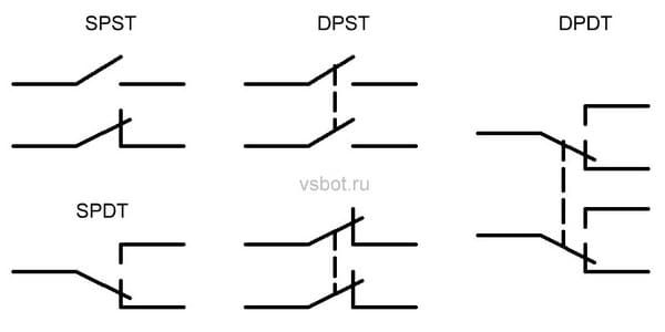
Relay contacts.
Depending on the design features, the intermediate relay contacts are normally open (closing), normally closed (opening) or changeover.

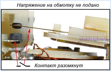
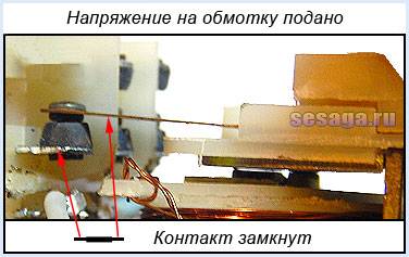
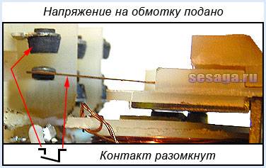
3.1. Normally open contacts.
Until the supply voltage is applied to the relay coil, its normally open contacts are always open. When voltage is applied, the relay is activated and its contacts close, completing the electrical circuit. The figures below show the operation of a normally open contact.
3.2. Normally closed contacts.
Normally closed contacts work in reverse: while the relay is de-energized, they are always closed. When voltage is applied, the relay is activated and its contacts open, breaking the electrical circuit. The figures show the operation of a normally open contact.
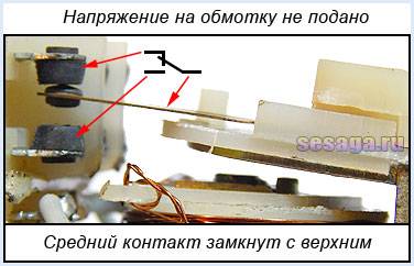
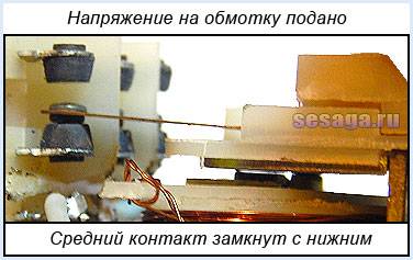
3.3. Changeover contacts.
For changeover contacts with de-energized coil average anchored contact is general and closed with one of the fixed contacts. When the relay is actuated, the middle contact, together with the armature, moves towards another fixed contact and closes with it, simultaneously breaking the connection with the first fixed contact. The figures below show the operation of a changeover contact.
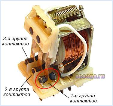
Many relays have not one, but several contact groups, which allows you to control several electrical circuits at the same time.
The intermediate relay contacts are subject to special requirements.They must have low contact resistance, high wear resistance, low welding tendency, high electrical conductivity and long service life.
During operation, the contacts with their current-carrying surfaces are pressed against each other with a certain force created by the return spring. The current-carrying surface of a contact in contact with the current-carrying surface of another contact is called contact surface, and the place where the current passes from one contact surface to another is called electrical contact.
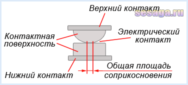
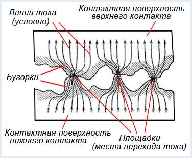
The contact of two surfaces does not occur over the entire apparent area, but only in separate areas, since even with the most careful processing of the contact surface, microscopic bumps and roughness will still remain on it. That's why total contact area will depend on the material, the quality of the processing of the contact surfaces and the compression force. The figure shows the contact surfaces of the top and bottom contacts in a greatly enlarged view.
At the place where current passes from one contact to another, an electrical resistance arises, which is called contact resistance. The magnitude of the contact resistance is significantly affected by the magnitude of the contact pressure, as well as the resistance of the oxide and sulfide films covering the contacts, since they are poor conductors.
In the process of long-term operation, the contact surfaces wear out and can be covered with soot deposits, oxide films, dust, and non-conductive particles. Contact wear can also be caused by mechanical, chemical and electrical factors.
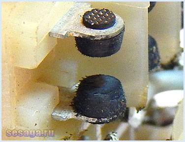
Mechanical wear occurs during sliding and impact of contact surfaces.However, the main reason for the destruction of contacts are electrical dischargesarising from the opening and closing of circuits, especially DC circuits with inductive loads. At the moment of opening and closing on the contact surfaces, the phenomena of melting, evaporation and softening of the contact material, as well as the transfer of metal from one contact to another, occur.


Silver, alloys of hard and refractory metals (tungsten, rhenium, molybdenum) and cermet compositions are used as materials for relay contacts. The most widely used silver, which has low contact resistance, high electrical conductivity, good technological properties and relatively low cost.
It should be remembered that there are no absolutely reliable contacts, therefore, to increase their reliability, parallel and series connection of contacts is used: when connected in series, contacts can break a large current, and parallel connection increases the reliability of closing the electrical circuit.
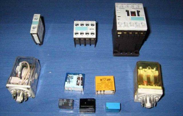
Types of intermediate relays
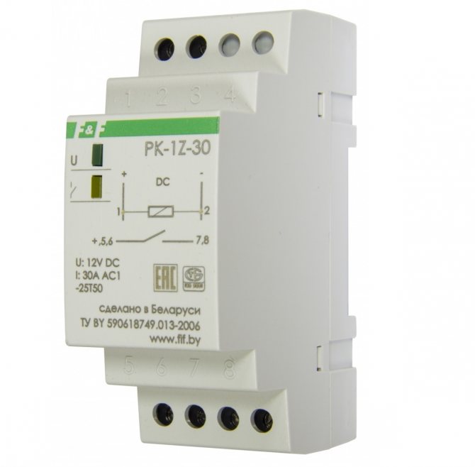
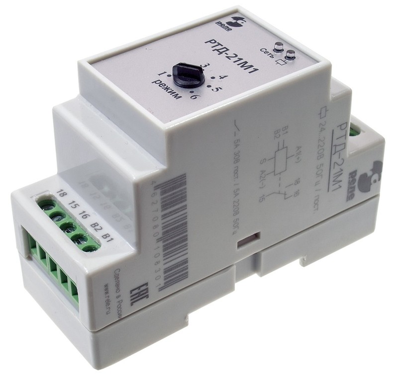
Intermediate relay for DIN rail
By design, they are divided into electromagnetic intermediate relays or mechanical and electronic devices. Mechanical relays can operate under different conditions. These are durable and reliable devices, but not accurate enough. Therefore, more often their analogues are mounted in the circuit - electronic relays on a DIN rail. Also, the relay can be installed on a flat surface. To do this, the latches of the locks need to be moved apart.
Devices are divided into the following categories according to their purpose.
- Combined interdependent devices operating in a group.
- Logic devices that operate on microprocessors in a circuit with digital relays.
- Measuring, with an adjustment mechanism, triggered by a certain signal level.
According to the way the RP works, there are direct ones that directly open or close the circuit, and indirect ones that work together with other devices. They do not open the circuit immediately after the received signal.
There are devices of the maximum type of switching, when the operation occurs at the moment of increasing the threshold value of the circuit parameter. The minimum type is triggered during derating.
According to the method of connecting to the circuit, there are primary ones that can be connected directly to the circuit. Secondaries are installed through inductors or capacitors.
Device types
For the correct operation of a solid state relay at low load currents commensurate with the leakage current, it is necessary to install a shunt resistance in parallel with the load. In relation to the communication method, there are: devices that perform loads of capacitive type, reductive type, weak induction; relays with random or instantaneous switching, used when instantaneous operation is required; relays with phase control, allow you to adjust the heating elements, incandescent lamps.
The rest is clearly demonstrated by the diagram: Scheme for switching on a solid state relay Characteristics Naturally, each company offering such devices has its own parameters and models. Now let's take a closer look at the manufacturing process of the device.
Power parameters - from 3 to 32 watts.
A generalized TTR circuit that clearly shows how an electronic device functions: 1 - control voltage source; 2 - optocoupler inside the relay case; 3 - load current source; 4 - load The current passing through the photodiode comes to the control electrode of the key transistor or thyristor. To avoid overvoltage when using a relay, be sure to purchase a varistor or a fast-acting fuse. Choosing and buying a solid state relay To buy a solid state relay, you should contact a specialized electronics store, where experienced specialists will help you choose a device in relation to the required power.
Characteristics of solid state relay
First, let's look at the input characteristics of the MOC opto-isolator, other opto-triacs are available. In devices that operate with alternating current, this is a thyristor or triac, and for devices with direct current, it is a transistor. The general final characteristics of the device and the features of its operation depend on the type and features of the decoupling.
The differences are insignificant, they do not affect the work in any way. A high level of performance allows you to avoid contact bounce during operation of the device.
Comments
Thus, when using an SSR, attention should be paid to the characteristics of the switching voltages. Such schemes are highly complex and it is better to buy a ready-made device.
The rest is clearly demonstrated by the diagram: Scheme for switching on a solid state relay Characteristics Naturally, each company offering such devices has its own parameters and models. For example, during the operation of powerful devices, it becomes necessary to use an additional element to remove thermal energy.
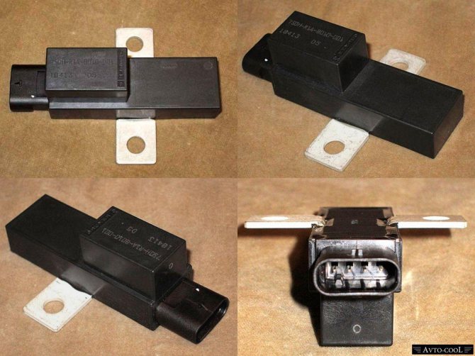
Let's check it in practice, let's say you are faced with such a product as in the figure below, and you want to know what it is. Cooling Another important factor for reliable operation of solid state relays is its operating temperature. In its design there are power switches on triacs, thyristors or transistors.
Solid state relay. What is it and how does it work? Test in practice
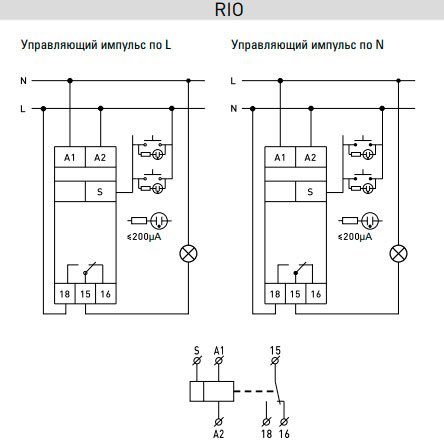
Several types of connection schemes
There are several mounting options, each of which has its own characteristics, advantages and disadvantages.
The designation of the RIO-1 relay contacts has the following interpretation:
- N - neutral wire;
- Y1 – enable input;
- Y2 – shutdown input;
- Y – on/off input;
- 11-14 - switching contacts of normally open type.
These designations are used on most relay models, but before connecting to the circuit, you should additionally familiarize yourself with them in the product data sheet.
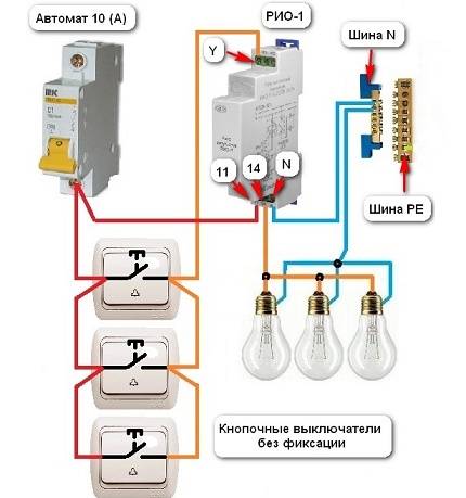
The presented electrification scheme is used to control the light from three places by means of a relay and three push-button switches without fixing the position
In this circuit, the power contacts of the relay use a current of 16 A. Protection of the control circuits and lighting systems is carried out by a 10 A circuit breaker. Therefore, the wires have a diameter of at least 1.5 mm2.


The pushbutton switches are connected in parallel. The red wire is the phase, it goes through all three pushbutton switches to the power contact 11. The orange wire is the switching phase, it comes to the Y input. Then it goes out of terminal 14 and goes to the light bulbs. The neutral wire from the bus is connected to the N terminal and to the fixtures.
If the light was initially turned on, then when you press any switch, the light will go out - there will be a short-term switching of the phase wire to the Y terminal and contacts 11-14 will open. The same will happen the next time you press any other switch. But contacts 11-14 will change position and the light will turn on.
The advantage of the above circuit over the pass-through and cross switches is obvious. However, in the event of a short circuit, fault detection will cause some difficulties, unlike the next option.
Such a scheme will save on wires, since the cross section of control cables can be reduced to 0.5 mm2. However, you will have to purchase a second protection device
This is a less common connection option. It is the same as the previous one, but the control and lighting circuits have their own circuit breakers for 6 and 10 A, respectively. This makes troubleshooting easier.
If it becomes necessary to control several lighting groups with a separate relay, then the circuit is somewhat modified.
This connection method is convenient to use to turn the lights on and off in groups. For example, immediately turn off a multi-level chandelier or lighting all jobs in the shop
Another option for using impulse relays is a system with centralized control.
The scheme is convenient in that you can turn off all the lights with one button when leaving the house. And upon return, turn it on in the same way
Two switches are added to this circuit to close and open the circuit. The first button can only turn on the lighting group.In this case, the phase from the “ON” switch will come to the Y1 terminals of each relay and contacts 11-14 will close.
The opening switch works in the same way as the first switch. But switching is carried out on the Y2 terminals of each switch and its contacts occupy the position of opening the circuit.
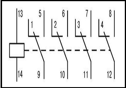
Relay marking
 Electromagnetic DC relay
To designate relay protection, markers of machines, devices, devices and the relay itself are used in the drawings. All devices are depicted in conditions without voltage in all power lines. According to the type of purpose of the relay device, three types of circuits are used.
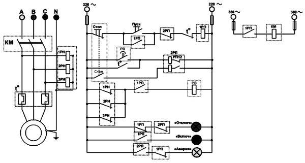
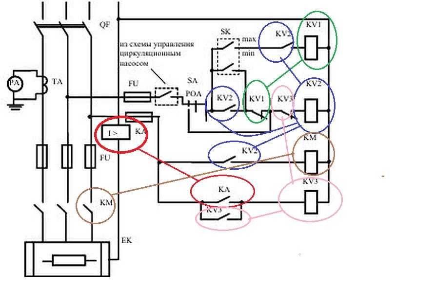
Schematic diagrams
The principal drawing is carried out along separate lines - operational current, current, voltage, signaling. The relays on it are drawn in a dissected form - the windings are on one part of the picture, and the contacts are on the other. Marking of the internal connection, clamps, sources of operational current on the circuit diagram is missing.
Wiring diagram
Wiring diagram example
Protection devices are marked on work diagrams intended for panel assembly, control or automation. All devices, clamps, connections or cables reflect the particular connection.
The wiring diagram is also called the executive.
Block diagrams
They allow to highlight the general structure of relay protection. The nodes and types of mutual connections will already be designated. To mark organs and nodes, rectangles with inscriptions or special indices are used to explain the purpose of using a particular element. The block diagram is also supplemented with conventional signs of logical connections.
Relay principles
The power relay, according to the principle of its action, either closes the electrical circuit, or opens it.How it happens: the voltage passing through the wiring “comes” to the relay coil. Then the winding attracts power contacts and performs its function in the electrical circuit. In the case when there is no voltage on the contacts of the control group, the contact with the index 30 is continuously connected to the contact 87a. When voltage appears, the contacts open and contact No. 30 is connected to contacts 87. A relay in which one of the types of contacts (87 or 87a) is missing can perform only one function: close or open the circuit.
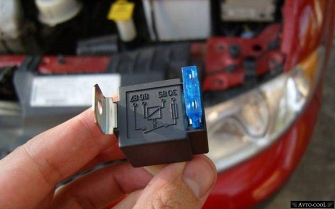
Relays from foreign manufacturers are often equipped with resistors and quenching diodes. They are located, as a rule, between contacts 85 and 86. This design of the relay allows for maximum protection of the circuit from voltage surges in the network.
Also, when buying and installing a relay, it is worth spending a couple of minutes studying it. The fact is that the location of the relay is not always standard. Relays from some manufacturers are equipped with a non-standard arrangement of contacts, which can play a trick on you.


It will also be interesting: How to quickly sell a car after an accident?
Long-term operation at high loads adversely affects the performance of the part and the integrity of its design as a whole. For example, at peak power moments, a spark may jump, which can lead to carbon deposits on the contacts, as a result of which the stable operation of the relay may be partially or completely disrupted. Because of this, with the passage of current, places of poor connection can serve as a place of increased danger. Excess heat and current growth are formed in them, which leads to heating of the contact zone.
The deformed plastic section generates a displacement of the contact fastening and, as a result, leads to the formation of gaps. The gaps between the contacts lead to even greater heating of the contact area. Therefore, it is necessary to occasionally check the relay for integrity and performance.
Types of electrical circuits
Such relays are called polarized. To explain the principle of operation of switching devices, if necessary, on their contact details, the qualifying symbols shown in Table. This can be clearly seen from the table, which shows the parameters of the Bestar BSC series relays.
Symbols for luminaires and spotlights I am glad that in the updated version of GOST, images of LED luminaires and luminaires with compact fluorescent lamps have been added.
The spring contact itself is fixed on the yoke. Cabinet, panel, control panel, one-sided service panel, local control post Cabinet, two-sided service panel Cabinet, switchboard, control panel of several one-sided service panels Cabinet, switchboard, control panel of several two-sided service panels Open panel Drawing in AutoCAD is conveniently performed using blocks and dynamic blocks.
Normally closed contacts N.
Conventional graphic symbols on electrical circuits and automation diagrams: GOST 2.
Conditional graphic designation and letter code of elements of electrical circuits Name of circuit element Letter code Electric machine.
The symbol of the polar relay, on the electrical circuit diagram, is applied in the form of a rectangle with two terminals and a bold dot at one of the connectors. How to check the relay?
How to read electrical diagrams. Radio components marking designation
Leading relay manufacturers
| Manufacturer | Image | Description |
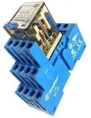
| Finder (Germany) | 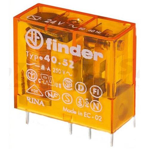 | Finder manufactures relays and timers and ranks third among European manufacturers. The manufacturer produces the relay:
The company's products are ISO 9001 and ISO 14001 certified. |
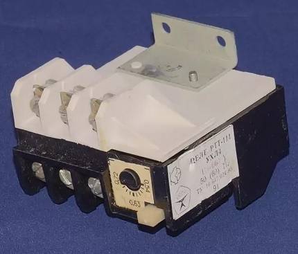
| JSC NPK Severnaya Zarya (Russia) | 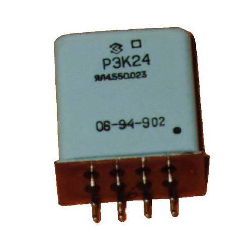 | The main products of the Russian manufacturer are anchor electromagnetic switching devices for special and industrial use, as well as low-current time relays with contact and non-contact outputs. |
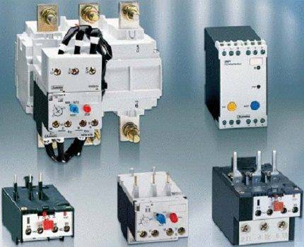
| Omron (Japan) | 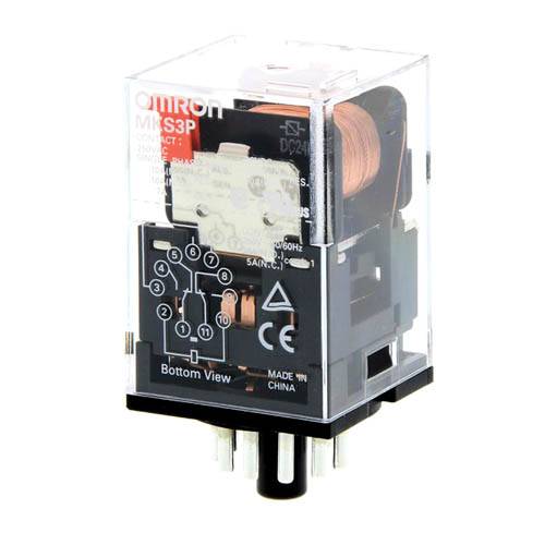 | The Japanese company produces highly reliable electronic components, including:
|
| COSMO Electronics (Taiwan) | 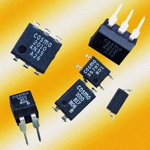 | The corporation produces radio components, among which relay components can be distinguished, which since 1994 have received ISO 9002 certification. The company's products are widely used in telecommunications, industrial and medical equipment, household appliances and automotive equipment. |
| American Zettler |  | For more than 100 years, Zettler has been a leader and has set the standard for performance and quality in electrical components. This manufacturer produces more than 40 types of CUs that meet the needs of a wide variety of projects. The company's products are widely used in telecommunications, computer peripherals, controls and other types of electronic and electrical equipment. |


