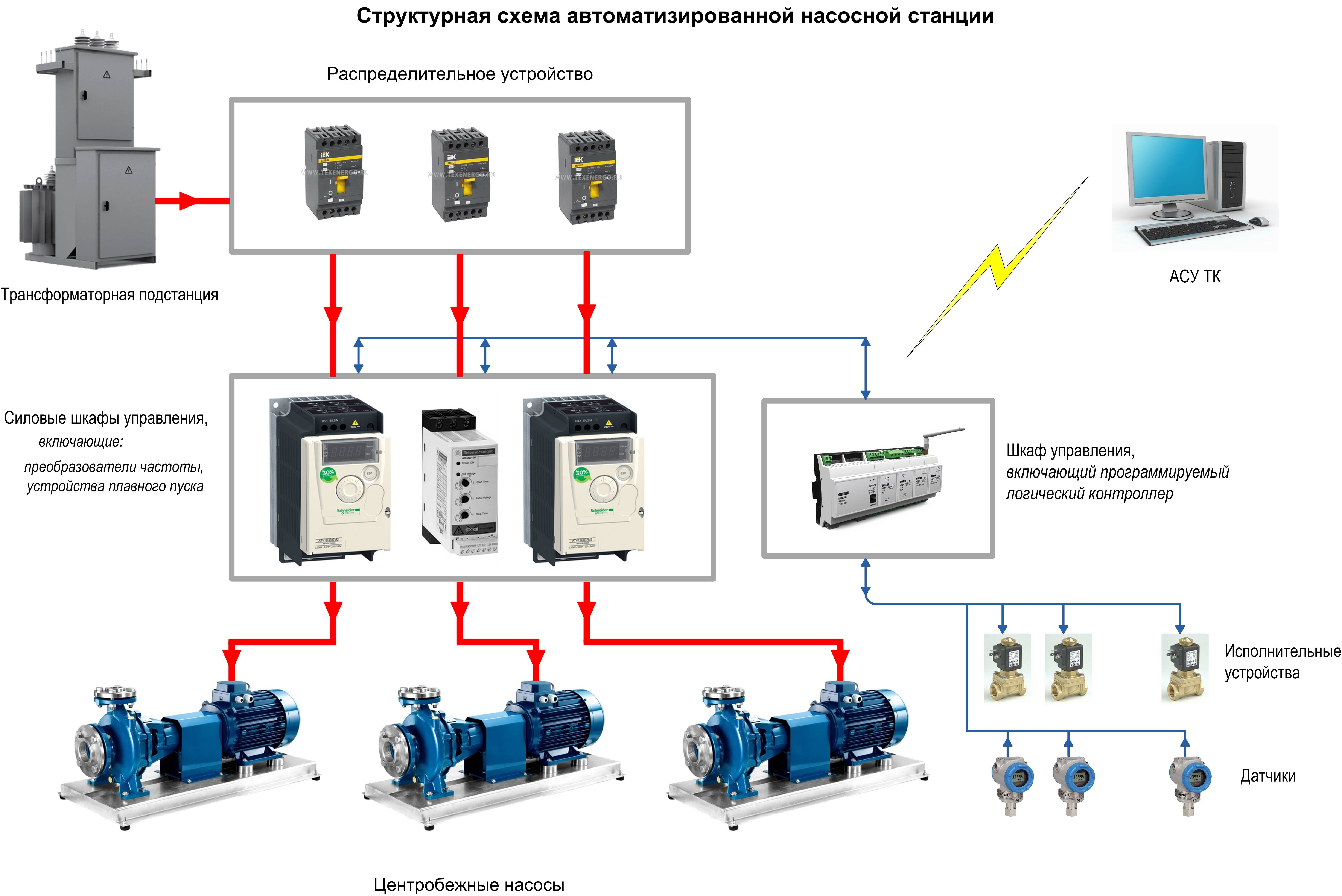
- Automatic systems and elements that ensure control and reliable operation of the pumping station system
- Possible problems with the installation
- The device and principle of operation of the pumping station
- Centrifugal borehole pump device
- Design features and principle of operation
- Connection of a pumping station
- Water supply from a well for permanent residence
- Connecting the pumping station to the water supply
- Well connection
- Principle of operation
- Advantages of a pump unit with a hydraulic tank
- The ideal scheme of operation of the fire water pumping station
- Local manual start
- Unconditional remote manual start
- Conditional remote start
- gate valve
- Exit to the mode
- dispatching
- Types and types of KNS
- Operation and features of the control unit
- Connection order: step by step instructions
- How to bring water from a well to a house with a deep pump?
- Purpose of the main parts of the station
Automatic systems and elements that ensure control and reliable operation of the pumping station system
It is necessary to say in more detail about modern systems as part of pumping stations that will ensure uninterrupted water supply to your home, as well as guarantee long-term operation of the pump.
So, when implementing a pumping station of any type, it is necessary to implement the following automation systems: - Protection against dry running of the pump (“Protection against “dry running” for a well pump using a pressure switch and level sensors.
Electrical circuit for protecting the pump from "dry running");
- The use of a pressure switch or electrocontact pressure gauge (signaling) to maintain pressure in the water supply system (“Water pressure switch (installation, characteristics, design, configuration)” and the article “Electrocontact pressure gauge (signaling) (principle of operation, application, design, marking and types) for water supply systems”.
In addition, if you are assembling a pumping station, which is said from A to Z, then information on choosing a receiver “Hydraulic receiver (hydraulic accumulator) for a house water pumping station (selection, design)”, as well as information on pipe installation “ Installation of metal-plastic (metal-polymer) pipes with threaded fittings”, “Do-it-yourself soldering of plastic (polypropylene) pipes”.
Now, having already a certain amount of information, and, accordingly, knowledge, we hope that the selection of components, as well as the assembly and connection of your pumping station will take place more deliberately, faster, and also with minimal deviations and errors.
The problem of water supply is at the forefront of creating a comfortable living environment in the country. This most often helps to solve the problem of connecting the pumping station to the water. Communications to provide a home is not just a banal plumbing facility with liquid Gander, after all, a complete home water supply system.
The need for an independent water supply, the basic needs of rural dwellers, leads to the constant use of water for cooking, sanitary and domestic use, as well as refrigerants in the heating system.
Household pumps are not always faced with such a variety of work functions.
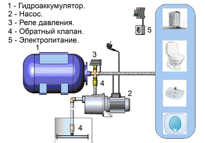
In addition, installing a pumping station in a private home allows evacuation and supply of water to increase system pressure if the existing pump is not strong enough to deliver liquids to the right place on the surface, in the garden, in the garden or at home. It offers various models on the market, but only a few components for a sufficient distribution of the base model, which is reflected in each pump installation system:
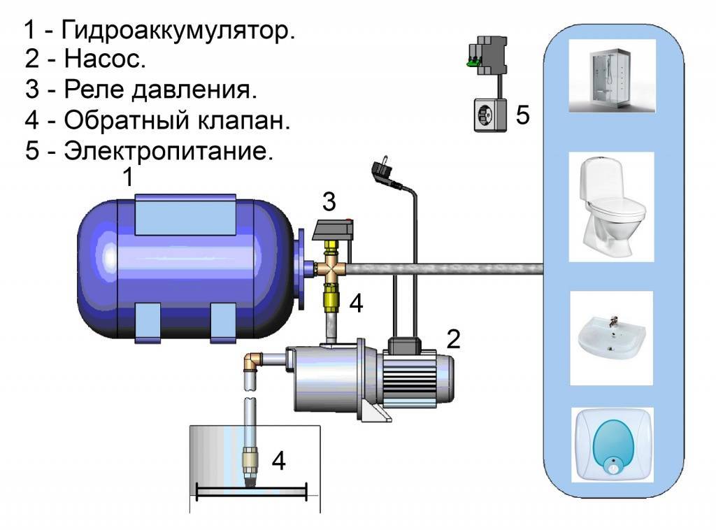
- storage tank;
- pump;
- control relay;
- non-return valve that does not allow leakage;
- filter.
A filter is needed, otherwise the grain of the grains will lead to rapid abrasive wear of machine parts.
Equipment location
The installation and operation of the pumping station ensures long-term reliable operation of the equipment, subject to the following conditions:
- when installing the station in a bunker, it is placed below the level of soil freezing in winter, which is at least two meters;
- The place where the station is installed (basement or casson) must be heated in winter;
- When assembling the connection plan by hand, it is necessary to prepare a stand, which is then installed on the station in order to prevent groundwater floods.
It is important!
Do not touch the equipment with walls so that the mechanical vibration of the operating mechanism does not affect the room.
Possible problems with the installation
There are several common problems:
- If the pump is switched on and off frequently, check the air pressure in the storage tank. If the value is too low, it must be pumped up. If this option does not work, you must contact the service center.
- It is possible to leak due to depressurization of the structural joints or mechanical damage to the hose.
- If there are drops of water on the air nipple of the accumulator, it is urgent to turn off this equipment and contact a qualified technician. Since this indicates damage to the membrane inside the storage tank.
- Water flows back due to a malfunction in the check valve device.
- If the pump does not want to turn on, the fault should be sought in the adjustment of the pressure switch.
These are the faults that are considered the most common.
The device and principle of operation of the pumping station
Does a pumping station differ in any way from a conventional electric pump and, if so, what are its advantages?
Firstly, the pumping station is able to provide good pressure, which is necessary for the full supply of water to the house and site.
Secondly, this system is fully automated and can work without constant monitoring by the owner - once installed, and you can not remember about it until the time for routine inspection and verification comes.
A conscious choice of a pumping station will be impossible if due attention is not paid to its design and basic components.
The main structural elements of the pumping station are a surface pump and a hydraulic accumulator (pressure hydraulic tank) connected to each other, as well as an automatic pressure switch that controls the operation of the pump. This is not enough for the autonomous functioning of the system.
But we will talk about the purpose and arrangement of additional components a little later, now we will focus on the main structural elements.
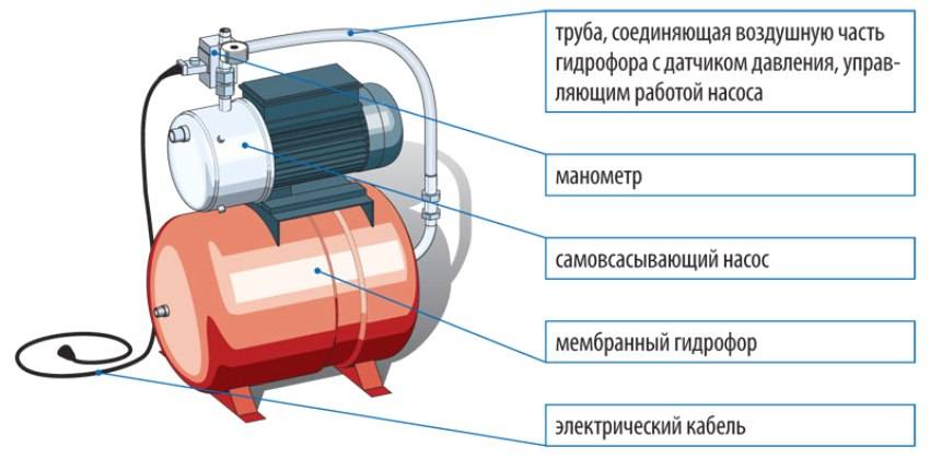
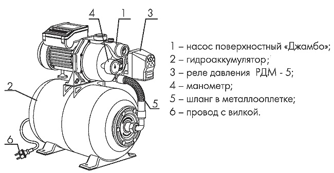
Pumping station device
1. Electric block.2. Outlet fitting.3. Inlet fitting.


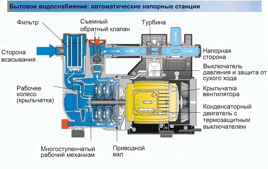
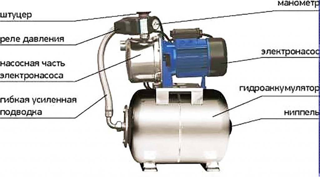
4. Electric motor.5. Manometer.6. Pressure switch.
7. Hose connecting pump and receiver.8. Hydraulic accumulator.9. Legs for fastening.
The "heart" of the pumping station is the pump. The design type of the pump used can be almost any - vortex, rotary, screw, axial, etc. - but for domestic water supply, as a rule, centrifugal-type pumps are used, which are distinguished by their simplicity of design and high efficiency.
The second important structural element of the pumping station - the accumulator - is, in fact, a storage tank (which actually follows from its name). However, the purpose of the accumulator is not only the accumulation of pumped water.
Without this element, the pump would turn on / off too often - every time the user turns the tap on his mixer. The absence of a hydraulic accumulator would also have a negative impact on the pressure of water in the system - the water would either flow from the tap in a thin stream, or would whip with too rapid a stream.
How can a pump, a hydraulic accumulator and a pressure switch put together be able to automatically provide us with water?
We will understand the principle of operation of the pumping station.
The pump, when turned on, begins to pump water, filling the storage tank with it. The pressure in the system then gradually increases. The pump will work until the pressure reaches the upper threshold. When the set maximum pressure is reached, the relay will operate and the pump will turn off.
What happens when the user turns on the tap in the kitchen or takes a shower? Water consumption will lead to a gradual emptying of the accumulator, and hence to a decrease in pressure in the system. When the pressure drops below the set minimum, the relay will automatically turn on the pump, and it will start pumping water again, compensating for its flow and increasing the pressure to the upper threshold value.
The upper and lower thresholds at which the pressure switch operates are set at the factory. The user, however, has the ability to make minor adjustments to the operation of the relay. The need for this may arise, for example, if it is required to increase the water pressure in the system.
Due to the fact that the pump, which is part of the pumping station, does not operate continuously, but only turns on from time to time, equipment wear is minimized.
A short video showing the principle of operation of the pumping station:
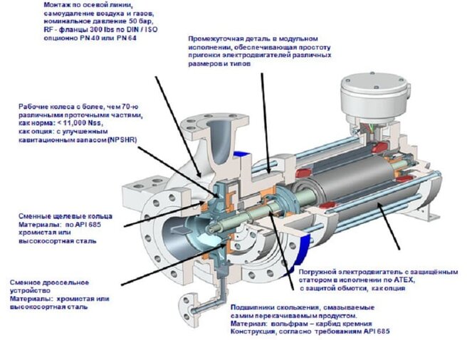
Centrifugal borehole pump device
If the pump drive motor is built-in, it is usually placed at the bottom of the device. Water intake when using pumps of this type can be carried out both through the upper and through the lower part of their housing.
Preference in this case is given to the intake of the pumped liquid through the lower part of the body, as this allows you to clean the deep part of the well from the silt and sand accumulating in it.
Submersible pumping devices, which is very convenient, are cooled by the liquid medium in which they are placed. This allows you to protect such devices from overheating, which can quickly render them unusable.
Centrifugal type deep-well pumps, although they are more complex in design than vibration devices, are distinguished by higher reliability, productivity and a longer service life.
The pump suspension must withstand a load exceeding the weight of the pump by 5–10 times
The main structural elements of vortex submersible pumps are the housing, a special glass, a drive motor and a vibrator.
The vibrator in these devices is the most complex structural element, consisting of an anchor, a rubber shock absorber and control washers.
The necessary conditions for fluid intake from the well, carried out by a vibration pump, are created by its rubber shock absorber, which is compressed and unclenched during the operation of such a device.
To ensure more efficient operation of submersible pumping equipment and ensure its protection from negative factors, various sensors are used that automatically stop the pump in case of emergency situations (too high content of silt and sand in the pumped liquid, a decrease in the water level in the well, etc.).
Design features and principle of operation
The pump consists of the following parts and assemblies:
- The energy source is an electric (or gasoline) engine mounted on the same shaft as the actual pumping part of the mechanism.
- Shaft supported by bearings.
- The impeller, on the surface of which the blades are placed.
- Casing with flow guide profiles.
- Shaft seals.
- Inlet pipe located on the axis of the product.
- Outlet pipe located at the outer wall of the housing tangentially to it.
Auxiliary nodes:
- Inlet and outlet hoses or pipelines.
- A shut-off valve that prevents fluid from flowing in the opposite direction.
- Filter.
- Manometer for measuring the pressure of a liquid medium.
- Dry running sensor that turns off the pump in the absence of liquid in the line.
- Taps and valves for pressure control.
The principle of operation of a centrifugal pump is simple:
- When the impeller rotates, its blades capture the liquid medium and drag it along
- Centrifugal forces arising from the rotation of the liquid, squeeze it to the outer walls of the housing, where excess pressure is created
- The pressure pushes the liquid medium into the outlet
- Under the action of the vacuum created in the center of the pump, the next portion of the liquid is sucked from the inlet pipe.
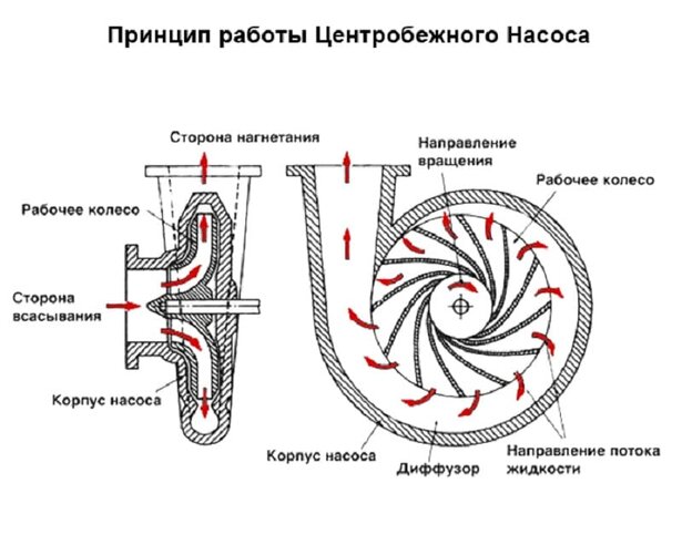
The principle of operation of a centrifugal pump
Changes and additions can be made to the design of a centrifugal pump, aimed at increasing its efficiency and adapting it to a specific pumped liquid.
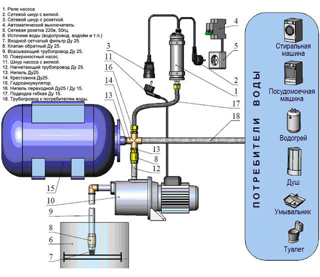
Connection of a pumping station
Choosing equipment and a place for installation is half the battle. You also need to correctly connect everything into a system - a water source, a station and consumers. The exact connection diagram of the pumping station depends on the chosen location. But anyway there is:


- Suction pipeline that descends into a well or well. He goes to the pumping station.
- The station itself.
- The pipeline going to consumers.
All this is true, only the strapping schemes will change depending on the circumstances. Let's consider the most common cases.
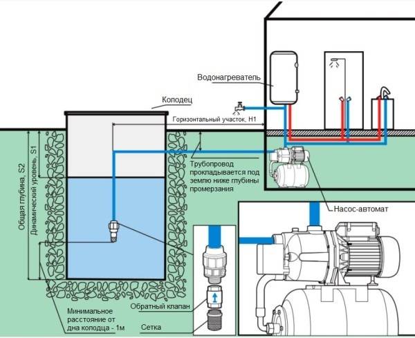
Water supply from a well for permanent residence
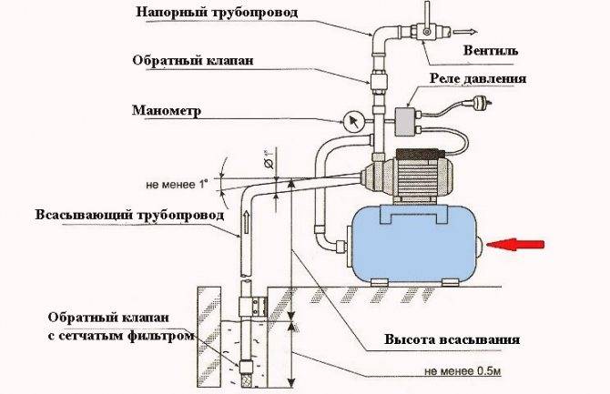
If the station is placed in a house or in a caisson somewhere on the way to the house, the connection scheme is the same.A filter (most often a regular mesh) is installed on the supply pipeline lowered into a well or well, a check valve is placed after it, then a pipe already goes. Why the filter - it is clear - to protect against mechanical impurities. A check valve is needed so that when the pump is turned off, water under its own weight does not flow back. Then the pump will turn on less often (it will last longer).
Scheme of installing a pumping station in a house
The pipe is brought out through the wall of the well at a depth just below the freezing level of the soil. Then it goes into the trench at the same depth. When laying a trench, it must be made straight - the fewer turns, the lower the pressure drop, which means that water can be pumped from a greater depth.
To be sure, you can insulate the pipeline (lay sheets of polystyrene foam on top, and then fill it with sand, and then with soil).
Passage option not through the foundation - heating and serious insulation are required
At the entrance to the house, the supply pipe passes through the foundation (the place of passage should also be insulated), in the house it can already rise to the installation site of the pumping station.
This method of installing a pumping station is good because if everything is done correctly, the system works without problems. The inconvenience is that it is necessary to dig trenches, as well as bring the pipeline out / in through the walls, and also in the fact that it is difficult to localize damage when a leak occurs. To minimize the chances of a leak, take proven quality pipes, lay a whole piece without joints. If there is a connection, it is desirable to make a manhole.
Detailed scheme of piping a pumping station when connected to a well or well
There is also a way to reduce the volume of earthworks: lay the pipeline higher, but insulate it well and additionally use a heating cable. This may be the only way out if the site has a high level of groundwater.
There is another important point - the well cover must be insulated, as well as the rings on the outside to the freezing depth. It's just that the section of the pipeline from the water mirror to the outlet to the wall should not freeze. For this, insulation measures are required.
Connecting the pumping station to the water supply
Often a pumping station is installed to increase the pressure in the water supply system with centralized water supply. In this case, a water pipe is connected to the station inlet (also through a filter and a check valve), and the outlet goes to consumers.
Scheme of connecting the pumping station to the water supply
It is advisable to put a shut-off valve (ball) at the inlet so that if necessary you can turn off your system (for repairs, for example). The second shut-off valve - in front of the pumping station - is needed to repair the pipeline or the equipment itself. Then it also makes sense to install a ball valve at the outlet - in order to cut off consumers if necessary and not drain water from the pipes.
Well connection
If the suction depth of the pumping station for the well is sufficient, the connection is no different. Unless the pipeline exits at the point where the casing pipe ends. A caisson pit is usually arranged here, and a pumping station can be installed right there.
Pumping station installation: well connection diagram
As in all previous schemes, a filter and a check valve are installed at the end of the pipe. At the entrance, you can put a filler tap through a tee. You will need it for the first start.
The main difference between this installation method is that the pipeline to the house actually runs along the surface or is buried to a shallow depth (not everyone has a pit below the freezing depth). If the pumping station is installed in the country, it's okay, the equipment is usually removed for the winter. But if the water supply is planned to be used in winter, it must be heated (with a heating cable) and insulated. Otherwise it won't work.
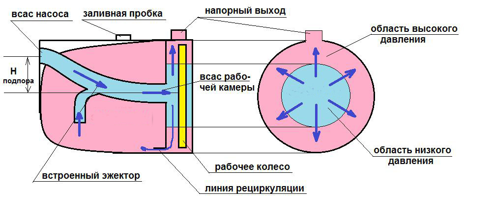
Principle of operation
The action of a centrifugal pump is based on the laws of hydrodynamics, on giving the liquid entering the closed spiral housing a dynamic effect through the rotating rotor blades. These blades have a complex shape with a bend in the direction opposite to the direction of rotation of the wheel. They are fixed between two disks mounted on an axle and communicate the dynamics of the fluid that fills the space between them.


The centrifugal force that arises in this case carries it from the central part of the casing, located in the region of the impeller rotation axis, to its periphery, and further to the outlet pipe. As a result of the action of centrifugal force, a rarefied area of reduced hydraulic pressure is created in the center of the body, which is filled with a new batch of liquid from the supply pipe. The required pressure in the pipeline is created by the pressure difference: atmospheric and internal, in the central part of the impeller. The operation of the pump is possible only when the housing is completely filled with water, in the “dry” state the wheel will rotate, but the necessary pressure difference will not occur and there will be no movement of liquid from the supply pipeline.
Advantages of a pump unit with a hydraulic tank
The pump is the main node for the delivery of water from the water intake to the place of its consumption. Let's analyze the device of the water supply pumping station and some of the advantages of using a hydraulic tank and a hydraulic accumulator:
To reduce the number of pump turns on and provide water supply with water in the event of a power outage, a large storage tank is used:
- it is installed at the top point, in the attic;
- in this way, water is drawn into it, and then runs by gravity to the places of consumption, while slight pressure is formed;
- however, this method requires a strong overlap and additional costs for installation work;
- insufficient pressure in the system calls into question the full operation of plumbing, can lead to its failure;
- there is a constant risk of flooding.
A more modern option is the use of a hydraulic accumulator, which allows you to achieve a constant pressure in the system:
- however, there remains a dependence on electricity;
- you can purchase an autonomous generator and make it automatically connect and start;
- however, this option requires additional financial costs.
As you can see, modern technologies allow us to offer many options for solving the issue of arranging home water supply away from the central highway. It is possible to use both of the above options in one system.
Thus, it remains possible to use sufficient pressure with the available electricity, and use water with less pressure when it is not available.
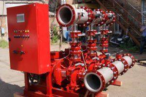
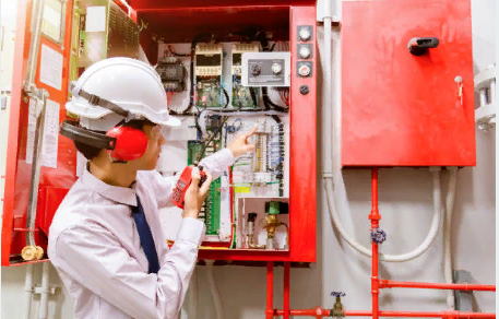
The ideal scheme of operation of the fire water pumping station
There are three modes of operation in the optimal scheme: local manual start, unconditional and conditional remote manual starts.
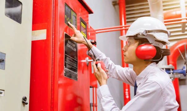
Local manual start
 Launch of the pumping station
Starting is carried out using the control panel and control station of the cabinet or instrument. The operator performs the start directly from the pumping station.
Unconditional remote manual start
Control cabinets have the possibility of remote access from the room on duty. Buttons are used to carry out the work. Remote monitoring devices of the pumping fire station are also used.
Conditional remote start
The remote start signal is generated using buttons located inside the fire cabinet. This is the optimal way to start the NSP.
gate valve
It is placed on the bypass pipeline of the meter. It is possible to connect to the cabinet. The drive of the electrified valve can be single- and three-phase.
Exit to the mode
Since there are two pumps in the system, one starts first. The reserve works only if there is no reaction from the main pump. Not reaching the mode in this case means the impossibility of reaching the set pressure in a certain time.
dispatching
Signals about the status of the pump are transmitted to the control room. The specialist will receive a “start”, “automatic”, “power”, “fault” signal, after which he can decide on further actions.
Types and types of KNS
The main part of any sewer system is pumping equipment, which can be of the following types:
- Self-priming;
- submersible;
- Console.
And the pumping station itself, given its location, happens:
- Partially buried;
- Buried;
- Ground.
In addition, all sewer stations are of two types: main and district. As for the main sewage pumping stations, they are used for pumping waste directly from a settlement or enterprise. But the regional ones are designed to divert effluents to a collector or treatment plant.
Also, KNS are divided into remote, automatic and manually controlled.
Remote work in such a way that it is possible to control and regulate their work from an equipped control room. Automatic fully controlled by sensors and devices. And as for the manual ones, all the work lies with the attendants.
Pumping stations also differ in the type of pumped effluent into four groups:
- The first group is intended for domestic waste water. It is used to divert wastewater from public buildings and residential households.
- The second group is for industrial wastewater.
- The third group is for storm networks.
- The fourth group is for precipitation.
Depending on the power of the KNS, there are mini, medium and large. Mini stations are mainly used directly in the bathroom or toilet. They are a small sealed container that is attached to the toilet. The most popular are medium pumping stations, they are used both for domestic and industrial purposes. Household differ from industrial ones in that only one pump can be installed in them. But industrial stations must be equipped with two pumps. Large sewage pumping stations are used exclusively in urban systems. They are equipped with the most powerful pumps in terms of parameters.
Operation and features of the control unit
For the full operation of the station, its management is necessary.The device of the station for home water supply is as follows:
- continuous automatic control of pressure in the system is performed around the clock;
- when it drops below a predetermined limit, the pump immediately turns on and the system is filled with water, pressure increases;
- when the pressure reaches above the set barrier, a relay is activated that turns off the pump;
- the pressure is at the same level until the water intake tap opens and it starts to fall.
To do this, you need a pressure gauge that measures pressure. And a pressure switch where the lower and upper limits are set.


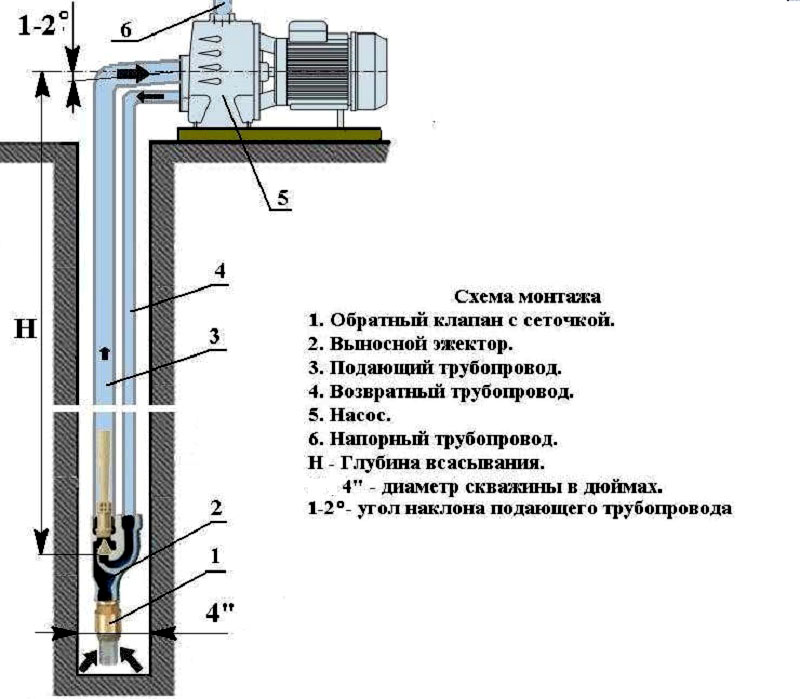

Connection order: step by step instructions
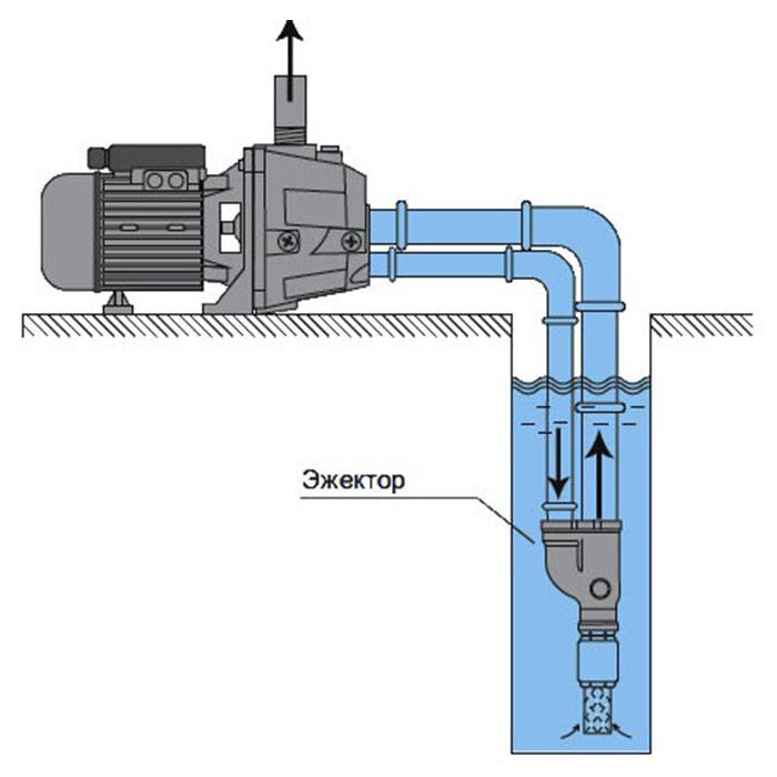
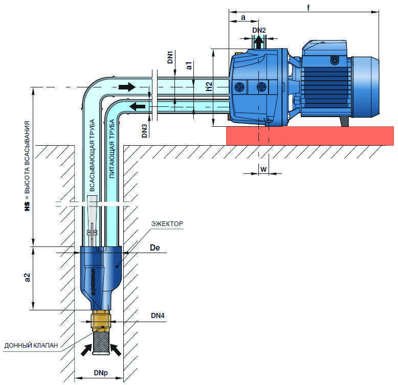
Pumping stations are suitable for equipment with relatively deep water intakes. If the depth of the groundwater table exceeds the maximum value specified by the manufacturer of the equipment, remote ejectors are used.
To install, perform the following steps:
- Lay a trench connecting the well and housing.
- Put pipes in it.
- Install plumbing (if not available).
- Install the unit in the selected location.
- The supply pipe is equipped with a filter and a check valve.
- Connect the line to the receiving pipe.
- Connect the unit to the water supply.
- Connect the equipment to the power supply.
- Fill the hydraulic tank with water.
- Perform a trial run of the station.
- Check joints.
- Set up the pressure switch.
The pipes of the external pipeline of the water supply system must be laid below the level to which the soil freezes. It is recommended to make a slight slope from the house to the well so that the water returns to the pump if it stops working. This will protect the device from overheating and damage due to dry running, i.e.work in the absence of water.
The same protective function is performed by a check valve that does not allow the liquid to leave the pipe and go into the well. When connecting a surface pump equipped with an ejector, it is required to connect another one to the suction pipe, which is connected to the ejector.
This assembly directs part of the incoming liquid to the base of the pipe through which the liquid enters, which greatly increases the productivity of the equipment. If a submersible pump is used, the work is performed differently. It is attached to the suction pipe and suspended on a strong stainless steel cable.
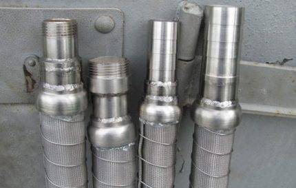 The lower end of the supply pipe should be equipped with a strainer so that sand and other particles do not pollute the water and damage the equipment.
Submersible pumps are conveniently attached to the finished head. Such a device is mounted on the upper part of the casing. It is believed that sealing the well with the help of a head allows to slightly increase its debit. To prevent the cable and cable from getting tangled, they are fixed to the pipe with plastic ties.
If the filter is already in the pump, they are limited to installing a check valve. The edge of the supply line of the surface pump must be located at a height of more than a meter. This minimum distance is half a meter for a submersible pump.
Connections of the unit with pipes must be made using American taps, valves are used to block any section and disconnect it for repair without damage to the rest of the system.
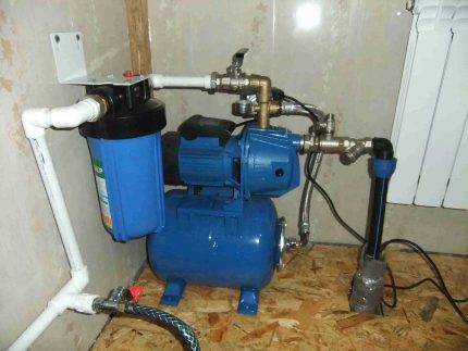 Before the station, it is recommended to install an additional coarse filter, and after it, a filter is installed that will ensure the purity of drinking water by removing unwanted impurities
The downhole filter installed in the working wears out over time, sand begins to seep through it. It is recommended to install an additional coarse filter at the pump inlet.
Power supply is provided by connecting a separate line to the equipment, equipped with an automatic shutdown device, care must be taken to ground it. Before starting, the device is filled with water through the opening provided for this.
In this case, the pressure in the hydraulic tank should be:
- about 1.5 bar for a container of less than 30 l;
- about 1.8 bar for 30-50 l;
- 2 bar or slightly less for a 50-100 l tank.
Then the water inlet hole is closed and the device is connected to the mains. You need to open the valve to let the air out. In a few minutes, water will flow from here. Otherwise, turn off the device and add a little more liquid.
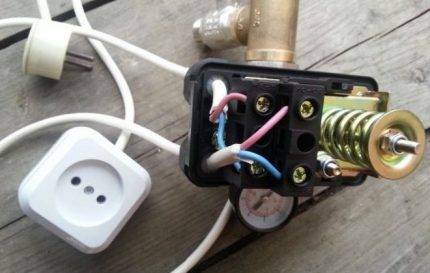 To adjust the pressure switch, it is necessary to remove the case from it in order to gain access to the screws with which the device is adjusted
Repeat switching on so that the device starts to work normally. Now you need to configure the relay. To do this, the GA will have to be emptied and then refilled. The indicators are set by rotating the corresponding screws.
How to bring water from a well to a house with a deep pump?
Having bought a suitable pump, you can begin to arrange water supply from a water source. This will require pipes through which water from the well will flow into the house. The diameter of the pipes should be 25–32 mm.Experts advise buying polymer products, as they do not corrode and are easy to bend. Further, in the process of operation, the pipes will be installed in the soil to a depth of 30–50 cm. To arrange water with your own hands, you will also need a septic tank. To make it easier to maintain, you will need to purchase a drainage pump.
Having prepared everything you need, you can get to work. The algorithm of actions is as follows:
- First of all, it is necessary to equip the pipe leaving the well with a head;
- Next, you need to install the caisson. To do this, you will need to dig a hole next to the well and place a plastic container inside it;
- After that, you need to install the pump in the well. To do this, it is necessary to pull the hose onto its branch pipe and securely fasten it with a metal clamp. After that, the hose, cable and safety rope are tied with electrical tape in increments of 1.2 m. Then the pump housing is tied with a steel cable, and the unit itself is lowered into the water. During installation, the device should not sway, otherwise hitting the wall will cause pump malfunctions;
- Next, you need to connect the hose to the pipes laid underground. All joints must be treated with sealant and tied with FUM tape;
- Before burying dug trenches, the water supply should be checked. To do this, you need to start the engine for a while and observe the amount of water flowing from the pipes. If the pump performance does not drop, trenches can be dug in.
It is very important not to damage the unit in the process of lowering it into the well. This must be done very slowly and carefully.
Otherwise, an expensive repair of the device may be required, or a complete replacement of the deep pump.
Purpose of the main parts of the station
The purpose of the pumping unit is well known - lifting water from a buried source and supplying it to the dwelling under pressure through a pressure pipeline. From the foregoing, it follows that technically a pumping station is an electric pump equipped with additional elements. allowing it to work automatically. It follows from this that the flow-pressure characteristics of the station are determined by the pump included in its composition.
The automation unit is designed to monitor the pressure in the water supply system at home. It can be relatively simple mechanical (with spring driving elements), pneumatic or electronic pressure switch with two settings: lower and upper threshold.
Sometimes there is a so-called. "jet" automation, fixing the beginning of each selection of water from the taps. In any case, this unit turns on and off the water intake of the pump by starting / stopping the drive motor.


The hydraulic accumulator is a hollow cylinder, inside of which there is an elastic (rubber, plastic) "pear", filled with water during the operation of the station.
This item is for:
- reducing the number of pump starts;
- for damping water hammer;
- creation of operational water supply;
- maintaining pressure inside the system when the pump is off.
Its operation is similar to a membrane expansion tank of a closed heating system: filling with water supplied by the pump, the “pear” expands, compressing the air between itself and the walls of the steel tank until the liquid pressure reaches the upper threshold value of the automation.However, the “pear” of the accumulator is constantly subjected to frequent alternating loads (unlike the membrane of the expansion tank). Therefore, it must be much stronger, although its heat resistance may be lower.
A hydraulic accumulator of sufficient capacity allows you to turn on / off the pumping unit less often. After all, the wear of the electric motor and the pump is not due to long-term operation, but due to frequent starts / stops. Inside the house, you can draw water as long as the excess water pressure in the system remains above the lower threshold.
Many homeowners (summer residents) do not understand the purpose of the accumulator.
In an effort to achieve budget savings, they build an autonomous water supply by connecting an ordinary garden pump to an automation unit, hoping that the latter will maintain water pressure directly in the pipes. Yes, this value can be kept stable in this way. However, the hydraulic accumulator performs a very important function - it dampens (softens) the hydraulic shocks in the system, i.e. sharp jumps in water pressure in pipes caused by changes in the flow velocity. This phenomenon occurs when the taps are opened, when a sharp and strong pressure of water is created.
Water hammer greatly reduces the service life of pipes and valves. Frequent pressure surges can damage faucets and other plumbing fixtures.