- Assigning Drivers to LEDs
- Key features
- Theory of power supply of LED lamps from 220 V
- AL9910
- Calculation example
- Types of LED Drivers
- Linear stabilizer
- Pulse stabilization
- How to make your own LED driver
- Instructions for assembling a driver for LEDs
- Option number 4 "the best circuit with a current-limiting capacitor, a resistor and a rectifier bridge.
- Classic driver circuit
- A brief overview and testing of popular LED lamps
- Option #1 - BBK P653F LED Bulb
- Option #2 - Ecola 7w LED lamp
- Option # 3 - collapsible lamp Ecola 6w GU5,3
- Option #4 - Jazzway 7.5w GU10 lamp
- How is a 220 V LED lamp arranged?
- Conclusion
Assigning Drivers to LEDs
The brightness of an LED lamp depends on 2 parameters: the current passing through it, and the identity of the characteristics of the semiconductors, since any discrepancy will damage the parts. But modern production is not able to provide completely identical crystal parameters.
It converts electricity
- sets its amplitude;
- straightens - makes it permanent;
- supplies the same current to all elements (slightly less than the maximum level) and does not allow them to breakdown.
Key features
The main difference of the driver is that at the input voltage for which it is designed (for example, 140-240 V), it sets the specified current level on the LEDs. In this case, the potential at the output of the device can be any.
It has 3 main characteristics:
- Rated current. It should not exceed the passport value of the LED, otherwise the diodes will burn out or burn dimly.
- Output voltage. Depends on the type of connection of semiconductors and their number. It is equal to the product of the drop in the potential of 1 element and their number and can vary over a wide range.
- Power. The entire operation of the device depends on the correct calculation of this characteristic. To do this, sum up the power of all elements and add 20-25% (overload margin).
For an LED lamp of 10 elements of 0.5 W, this parameter will be equal to 5W. Taking into account the overload, you should choose a driver for 6-7 W.
But the last 2 parameters (power consumption and output voltage) directly depend on the emission spectrum of the LED. For example, XP-E elements (red) at 1.9-2.5 V consume 0.75 W, and green - 1.25 W when powered at 3.3-3.9 V. It turns out that the driver is 10 W able to power 7 diodes of one color or 12 of another.
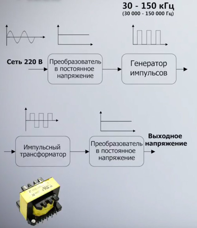
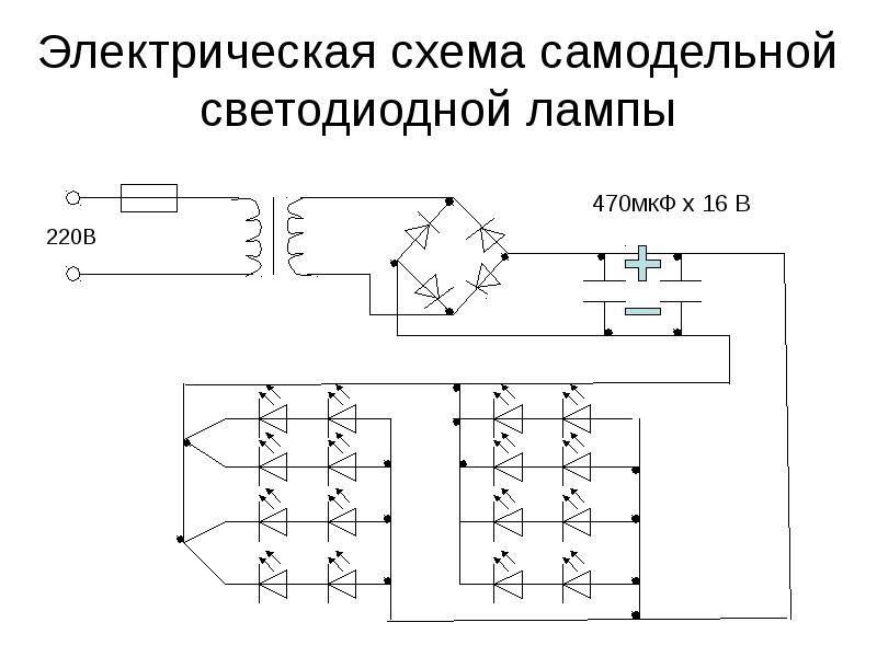
Theory of power supply of LED lamps from 220 V
An ice lamp, a ceiling tape or a backlight in a modern TV is a collection of several powerful small LEDs placed in the space as needed.
If each of them is capable of passing a current of 1 A at a voltage of 3.3 V, then they cannot be included in the lighting network - they will immediately burn out. You can use a resistor divider, but they will dissipate more power. Therefore, the efficiency of the lamp will be small.
Drivers are used to reduce voltage and convert current to direct current.Inside these devices there can be various current stabilizers, capacitive-resistive dividers, etc.
The circuit may include transistors, microcircuits, capacitors, etc. Such converters change the voltage and provide the required amount of current to each element.
AL9910
Diodes Incorporated has created one very interesting LED driver IC: the AL9910. It is curious in that its operating voltage range allows it to be connected directly to a 220V network (through a simple diode rectifier).
Here are its main characteristics:
- input voltage - up to 500V (up to 277V for a change);
- built-in voltage regulator for powering the microcircuit, which does not require a quenching resistor;
- the ability to adjust the brightness by changing the potential on the control leg from 0.045 to 0.25V;
- built-in overheating protection (activated at 150°С);
- operating frequency (25-300 kHz) is set by an external resistor;
- an external field-effect transistor is required for operation;
- Available in 8-legged SO-8 and SO-8EP cases.
The driver assembled on the AL9910 chip does not have galvanic isolation from the network, therefore it should be used only where direct contact with the circuit elements is impossible.
The chip is available in two versions: AL9910 and AL9910a. They differ in the minimum trigger voltage (15 and 20V, respectively) and the output voltage of the internal regulator ((7.5 or 10V, respectively). The AL9910a also has slightly higher consumption in sleep mode.
The cost of microcircuits is about 60 rubles / piece.
Typical switching circuit (without dimming) looks like this:
Here the LEDs are always lit at full power, which is set by the value of the resistor Rsense:
Rsense = 0.25 / (ILED + 0.15⋅ILED)


To adjust the brightness, the 7th leg is torn off from Vdd and hung on a potentiometer that outputs from 45 to 250 mV. Also, the brightness can be adjusted by applying a PWM signal to the PWM_D pin. If this output is grounded, the microcircuit is turned off, the output transistor is completely closed, the current consumed by the circuit drops to ~0.5mA.
The generation frequency should lie in the range from 25 to 300 kHz and, as mentioned earlier, it is determined by the resistor Rosc. The dependence can be expressed by the following equation:
fosc = 25 / (Rosc + 22), where Rosc - resistance in kiloohms (usually from 75 to 1000 kOhm).
The resistor is connected between the 8th leg of the microcircuit and the “ground” (or the GATE pin).
The inductance of the inductor is calculated according to the terrible formula at first glance:
L ≥ (VIN – VLEDs)⋅VLEDs / (0.3⋅VIN⋅fosc⋅ILED)
Calculation example
For example, let's calculate the parameters of the chip binding elements for two Cree XML-T6 LEDs connected in series and the minimum supply voltage (15 volts).
So, let's say we want the chip to operate at 240 kHz (0.24 MHz). Resistor value Rosc should be:
Rosc = 25/fosc - 22 = 25/0.24 - 22 = 82 kOhm
Move on. The rated current of the LEDs is 3A, the operating voltage is 3.3V. Therefore, 6.6V will drop on two LEDs connected in series. With these inputs, we can calculate the inductance:
L ≥ (VIN – VLEDs)⋅VLEDs / (0.3⋅VIN⋅fosc⋅ILED) = (15-6.6)⋅6.6 / (0.3⋅15⋅240000⋅3) = 17 µH
Those. greater than or equal to 17 µH. Take a common factory inductance of 47 uH.
It remains to calculate Rsense:
Rsense = 0.25 / (ILED + 0.15⋅ILED) = 0.25 / (3 + 0.15⋅3) = 0.072 Ohm
As a powerful output MOSFET, let's take some suitable in terms of characteristics, for example, the well-known N-channel 50N06 (60V, 50A, 120W).
And here, in fact, what scheme we got:
Despite the minimum of 15 volts indicated in the datasheet, the circuit starts perfectly from 12, so it can be used as a powerful car spotlight. Actually, the above circuit is the actual driver circuit of YF-053CREE 20W LED spotlight, which was obtained by reverse engineering.
The PT4115, CL6808, CL6807, SN3350, AL9910, QX5241 and ZXLD1350 LED driver ICs we have reviewed allow you to quickly assemble a driver for high-power LEDs with your own hands and are widely used in modern LED fixtures and lamps.
The following radio components were used in the article:
| LEDs | ||
|---|---|---|
| Cree XM-L T6 (10W, 3A) | 135 rub/pc. | |
| Cree XM-L2 T6 (10W, 3A, copper) | 360 rub/pc. | |
| transistors | ||
| 40N06 | 11 rub/pc. | |
| IRF7413 | 14 rub/pc. | |
| IPD090N03L | 14 rub/pc. | |
| IRF7201 | 17 rub/pc. | |
| 50N06 | 12 rub/pc. | |
| Schottky diodes | ||
| STPS2H100A (2A, 100V) | 15 rub/pc. | |
| SS34 (3A, 40V) | 90 kop/pc. | |
| SS56 (5A, 60V) | 3.5 rub/piece |
Types of LED Drivers
All drivers for LEDs can be divided according to the principle of current stabilization. Today there are two such principles:
- Linear.
- Pulse.
Linear stabilizer
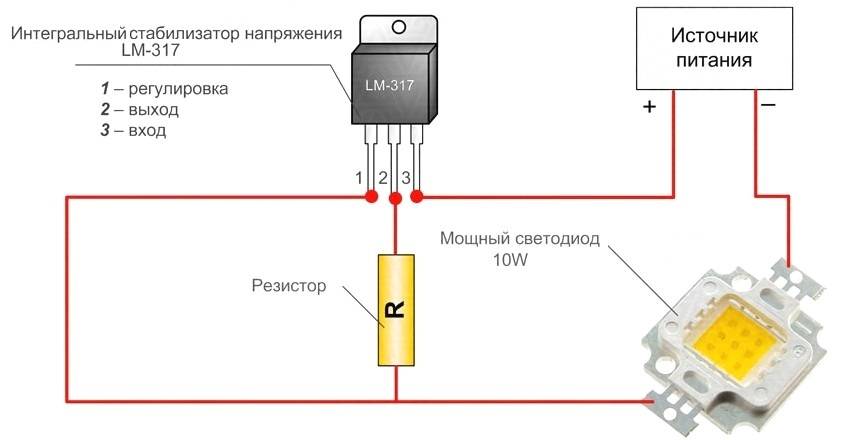
Suppose we have a powerful LED that needs to be lit. Let's assemble the simplest scheme:
 Diagram explaining the linear principle of current regulation
We set the resistor R, which acts as a limiter, to the desired current value - the LED is on.If the supply voltage has changed (for example, the battery is running low), we turn the resistor slider and restore the required current. If increased, then in the same way the current is reduced. This is exactly what the simplest linear regulator does: monitors the current through the LED and, if necessary, “turns the knob” of the resistor. He only does it very quickly, having time to respond to the slightest deviation of the current from the set value. Of course, the driver has no handle, its role is played by a transistor, but the essence of the explanation does not change from this.


What is the disadvantage of a linear current stabilizer circuit? The fact is that a current also flows through the regulating element and uselessly dissipates power, which simply heats the air. Moreover, the higher the input voltage, the higher the losses. For LEDs with a low operating current, such a circuit is suitable and successfully used, but it is more expensive to power powerful semiconductors with a linear driver: drivers can eat up more energy than the illuminator itself.
The advantages of such a power supply scheme include the relative simplicity of circuitry and the low cost of the driver, combined with high reliability.
 Linear driver to power an LED in a flashlight
Pulse stabilization
Before us is the same LED, but we will assemble a slightly different power circuit:
 Scheme explaining the principle of operation of the pulse-width stabilizer
Now, instead of a resistor, we have a KN button and a storage capacitor C has been added. We apply voltage to the circuit and press the button. The capacitor begins to charge, and when the operating voltage on it is reached, the LED lights up. If you continue to keep the button pressed, the current will exceed the allowable value, and the semiconductor will burn out. We release the button.The capacitor continues to power the LED and gradually discharges. As soon as the current drops below the value allowed for the LED, we press the button again, feeding the capacitor.
So we sit and periodically press the button, maintaining the normal mode of operation of the LED. The higher the supply voltage, the shorter the presses will be. The lower the voltage, the longer the button will have to be pressed. This is the principle of pulse-width modulation. The driver monitors the current through the LED and controls the key assembled on a transistor or thyristor. He does it very quickly (tens and even hundreds of thousands of clicks per second).
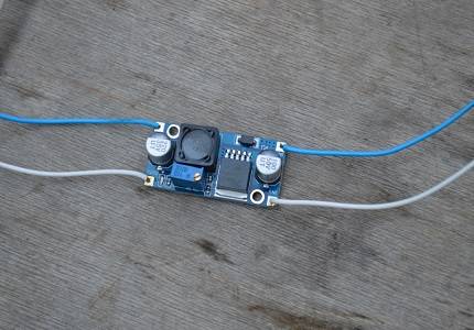
At first glance, the work is tedious and complicated, but not for an electronic circuit. But the efficiency of a switching stabilizer can reach 95%. Even when powered by heavy-duty LED spotlights, power loss is minimal, and key driver elements do not require powerful heat sinks. Of course, switching regulators are somewhat more complicated in design and more expensive, but all this pays off with high performance, exceptional quality of current stabilization and excellent weight and size indicators.
 This switching driver is capable of delivering current up to 3 A without any heatsinks.
How to make your own LED driver
With the help of ready-made microcircuits, even a novice radio amateur is able to assemble a converter for LEDs of various powers. This requires the ability to read electrical circuits and experience with a soldering iron.
You can assemble a current stabilizer for 3-watt stabilizers using a microcircuit from the Chinese manufacturer PowTech - PT4115.This IC can be used for LED elements with a power of more than 1 W and consists of control units with a fairly powerful output transistor. The converter based on PT4115 has high efficiency and minimal set of components.
As you can see, with experience, knowledge and desire, you can assemble an LED driver in almost any scheme. Now let's look at a step-by-step instruction for creating the simplest current converter for 3 LED elements with a power of 1 W each, from a mobile phone charger. By the way, this will help you better understand the operation of the device and later move on to more complex circuits designed for a larger number of LEDs and tape.
Instructions for assembling a driver for LEDs
| Image | Stage description |
|---|---|
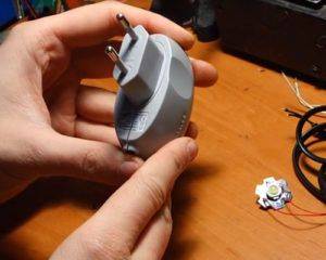 | To assemble the stabilizer, you will need an old mobile phone charger. We took from Samsung, they are so reliable. Carefully disassemble the charger with parameters of 5 V and 700 mA. |
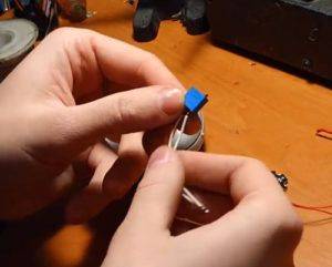 | We also need a variable (tuner) resistor of 10 kOhm, 3 LEDs of 1 W each and a cord with a plug. |
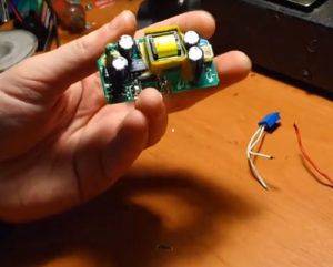 | This is what the disassembled charger looks like, which we will redo. |
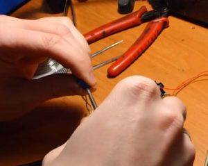
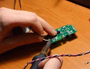 | We solder the output resistor to 5 kOhm and put a "trimmer" in its place. |
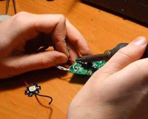 | Next, we find the output to the load and, having determined the polarity, solder the LEDs pre-assembled in series. |
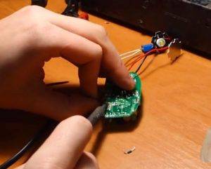 | We solder the old contacts from the cord and in their place we connect the wire with the plug. Before checking the LED driver for performance, you need to make sure that the connections are correct, that they are strong and that nothing creates a short circuit. Only then can you start testing. |
 | With a trimming resistor, we begin the adjustment until the LEDs begin to glow. |
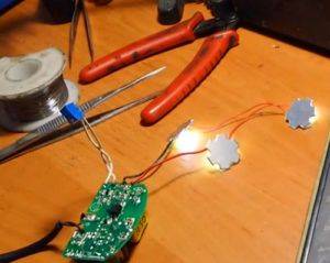 | As you can see, the LED elements are lit. |
 | With a tester, we check the parameters we need: output voltage, current and power. If necessary, adjust the resistor. |
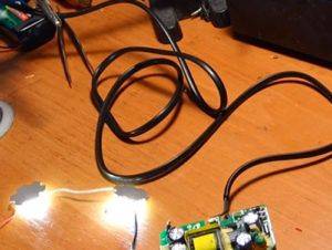 | That's all! The LEDs burn normally, nothing sparks or smokes anywhere, which means the alteration was successful, with which we congratulate you. |
As you can see, making a simple LED driver is very simple. Of course, this scheme may not be interesting for experienced radio amateurs, but for a beginner it is perfect for practice.
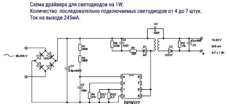
Option number 4 "the best circuit with a current-limiting capacitor, a resistor and a rectifier bridge.
I consider this option for connecting an indicator LED to a 220 volt network the best. The only drawback (if I may say so) of this scheme is that it has the most details. The advantages include the fact that it does not have elements that are excessively heated, since there is a diode bridge, the LED operates with two half-cycles of alternating voltage, therefore there is no flicker visible to the eye. This scheme consumes the least electricity (economical).
This scheme works as follows. Instead of a current-limiting resistor (which was 24 kOhm in previous circuits), there is a capacitor, which eliminates the heating of this element. This capacitor must be of a film type (not an electrolyte) and is designed for a voltage of at least 250 volts (it is better to set it to 400 volts). It is by selecting its capacitance that you can adjust the amount of current in the circuit. AT table in the picture the capacitances of the capacitor and the corresponding currents are given. There is a resistor in parallel with the capacitor, the task of which is only to discharge the capacitor after disconnecting the circuit from the 220 volt network. It does not take an active role in the power supply circuit of the indicator LED from 220 V.
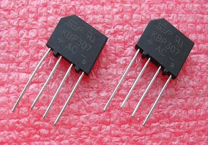
Next is the usual rectifier diode bridge, which turns alternating current into direct current. Any diodes (ready-made diode bridge) will do, in which the maximum current strength will be greater than the current consumed by the indicator LED itself. Well, the reverse voltage of these diodes must be at least 400 volts. You can supply the most popular 1N4007 series diodes. They are cheap, small in size, designed for current up to 1 ampere and a reverse voltage of 1000 volts.
There is another resistor in the circuit, a current limiting one, but it is needed to limit the current that arises from random voltage surges coming from the 220 volt network itself. Suppose that if someone in the neighborhood uses powerful devices containing coils (an inductive element that contributes to short-term voltage spikes), then a short-term increase in mains voltage is formed in the network. The capacitor passes this voltage surge unhindered. And since the magnitude of the current of this surge is sufficient to disable the indicator LED, a current-limiting resistor is provided in the circuit that protects the circuit from such voltage drops in the electrical network. This resistor heats up slightly compared to the resistors in the previous circuits. Well, the indicator LED itself. You choose it yourself, its brightness, color, size.After choosing the LED, select the appropriate capacitor of the desired capacitance, guided by the table in the figure.


P.S. An alternative option for electric LED backlighting can be a classic circuit for connecting a neon light bulb (in parallel with which a resistor is placed somewhere around 500kOhm-2mOhm). If we compare in terms of brightness, then all the same it is more for LED backlighting, but if special brightness is not required, then it is quite possible to get by with this version of the circuit on a neon lamp.
Classic driver circuit
For self-assembly of the LED power supply, we will deal with the simplest pulse-type device that does not have galvanic isolation. The main advantage of this kind of circuits is simple connection and reliable operation.
The 220 V converter circuit is presented as a switching power supply. When assembling, all electrical safety rules must be observed, since there are no limits on current output
The scheme of such a mechanism is composed of three main cascade regions:
- Voltage separator on capacitance.
- Rectifier.
- Surge Protectors.
The first section is the opposition to the alternating current on the capacitor C1 with a resistor. The latter is required solely for self-charging of an inert element. It does not affect the operation of the circuit.
 The nominal value of the resistor can be in the range of 100 kOhm-1 MΩ, with a power of 0.5-1 W. The capacitor must be electrolytic, and its effective voltage peak value is 400-500 V
When the formed half-wave voltage passes through the capacitor, the current flows until the plates are fully charged.The smaller the capacity of the mechanism, the less time will be spent on its full charge.
For example, a device with a volume of 0.3-0.4 microfarads is charged during 1/10 of the half-wave period, that is, only a tenth of the passing voltage will pass through this section.
The straightening process in this section is carried out according to the Graetz scheme. The diode bridge is selected based on the rated current and reverse voltage. In this case, the last value should not be less than 600 V
The second stage is an electrical device that converts (rectifies) alternating current into a pulsating one. Such a process is called a two-way process. Since one part of the half-wave has been smoothed out by a capacitor, the output of this section will have a direct current of 20-25 V.
Since the power supply of the LEDs should not exceed 12 V, a stabilizing element must be used for the circuit. For this, a capacitive filter is introduced. For example, you can use the model L7812
The third stage operates on the basis of a smoothing stabilizing filter - an electrolytic capacitor. The choice of its capacitive parameters depends on the load force.
Since the assembled circuit reproduces its work immediately, you can not touch the bare wires, because the current carried reaches tens of amperes - the lines are first insulated.
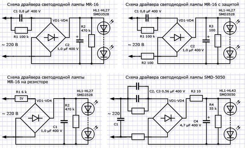
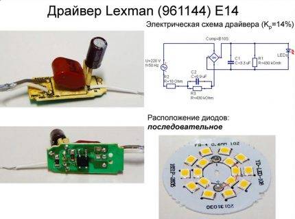
A brief overview and testing of popular LED lamps
Although the principles of constructing driver circuits for various lighting devices are similar, there are differences between them both in the sequence of connecting elements and in their choice.
Consider the circuits of 4 lamps that are sold in the public domain. If desired, they can be repaired with your own hands.
If there is experience with controllers, you can replace the elements of the circuit, re-solder it, and slightly improve it.
However, scrupulous work and efforts to find elements are not always justified - it is easier to buy a new lighting fixture.
Option #1 - BBK P653F LED Bulb
The BBK brand has two very similar modifications: the P653F lamp differs from the P654F model only in the design of the radiating unit. Accordingly, both the driver circuit and the design of the device as a whole in the second model are built according to the principles of the first device.


The board has compact dimensions and a well-thought-out arrangement of elements, for fastening of which both planes are used. The presence of ripples is due to the absence of a filter capacitor, which should be at the output
It is easy to find flaws in the design. For example, the installation location of the controller: partly in a radiator, in the absence of insulation, partly in a plinth. The assembly on the SM7525 chip produces 49.3 V at the output.
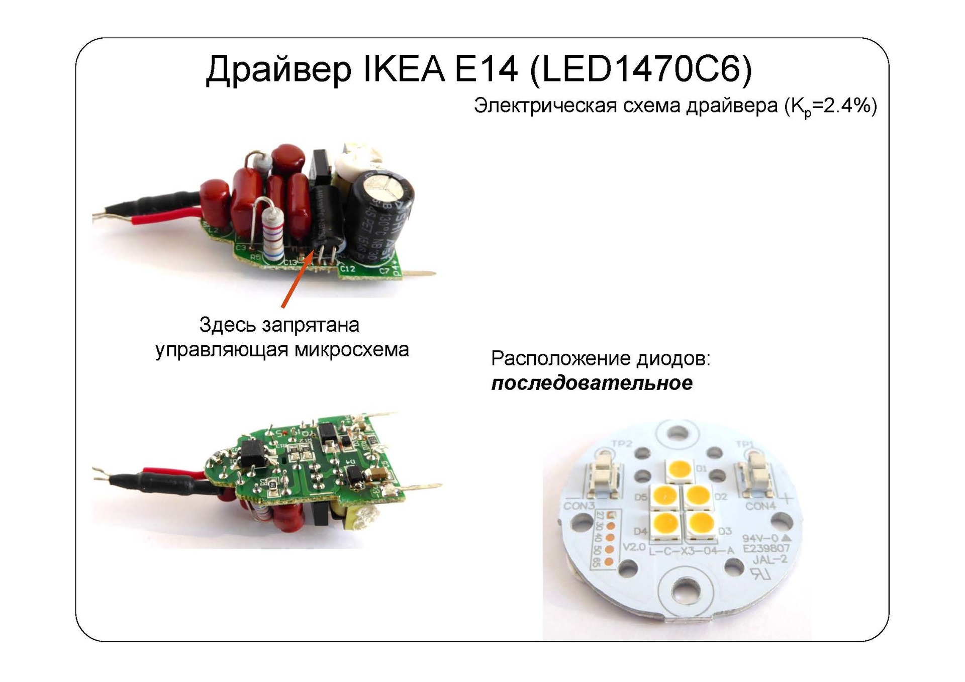
Option #2 - Ecola 7w LED lamp
The radiator is made of aluminum, the plinth is made of heat-resistant gray polymer. On a printed circuit board half a millimeter thick, 14 diodes connected in series are fixed.
Between the heatsink and the board is a layer of heat-conducting paste. The plinth is fixed with self-tapping screws.
The controller circuit is simple, implemented on a compact board. The LEDs heat the base board up to +55 ºС. There are practically no ripples, radio interference is also excluded
The board is completely placed inside the base and connected with short wires. The occurrence of short circuits is impossible, since there is plastic around - an insulating material. The result at the output of the controller is 81 V.
Option # 3 - collapsible lamp Ecola 6w GU5,3
Thanks to the collapsible design, you can independently repair or improve the device driver.
However, the impression is spoiled by the unsightly appearance and design of the device. The overall radiator makes the weight heavier, therefore, when attaching the lamp to the cartridge, additional fixation is recommended.
The board has compact dimensions and a well-thought-out arrangement of elements, for fastening of which both planes are used. The presence of ripples is due to the absence of a filter capacitor, which should be at the output
The disadvantage of the circuit is the presence of noticeable pulsations of the light flux and a high degree of radio interference, which will necessarily affect the service life. The basis of the controller is the BP3122 microcircuit, the output indicator is 9.6 V.
We reviewed more information about Ecola brand LED bulbs in our other article.
Option #4 - Jazzway 7.5w GU10 lamp
The external elements of the lamp detach easily, so the controller can be reached quickly enough by unscrewing two pairs of self-tapping screws. The protective glass is held on by latches. There are 17 serial-coupled diodes on the board.
However, the controller itself, located in the base, is generously filled with compound, and the wires are pressed into the terminals. To release them, you need to use a drill or apply soldering.
The disadvantage of the circuit is that a conventional capacitor performs the function of a current limiter. When the lamp is turned on, current surges occur, resulting in either a burnout of the LEDs or a failure of the LED bridge
No radio interference is observed - and all due to the absence of a pulse controller, but at a frequency of 100 Hz, noticeable light pulsations are observed, reaching up to 80% of the maximum indicator.
The result of the controller's operation is 100 V at the output, but according to the general assessment, the lamp is more likely to be a weak device. Its cost is clearly overestimated and equated to the cost of brands that are distinguished by stable product quality.
We have given other features and characteristics of the lamps of this manufacturer in the following article.
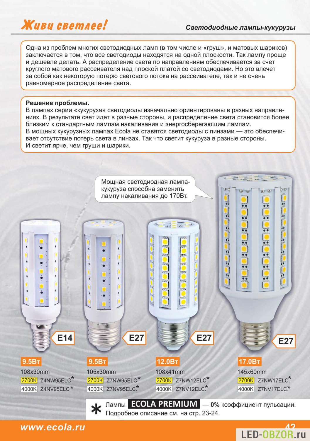
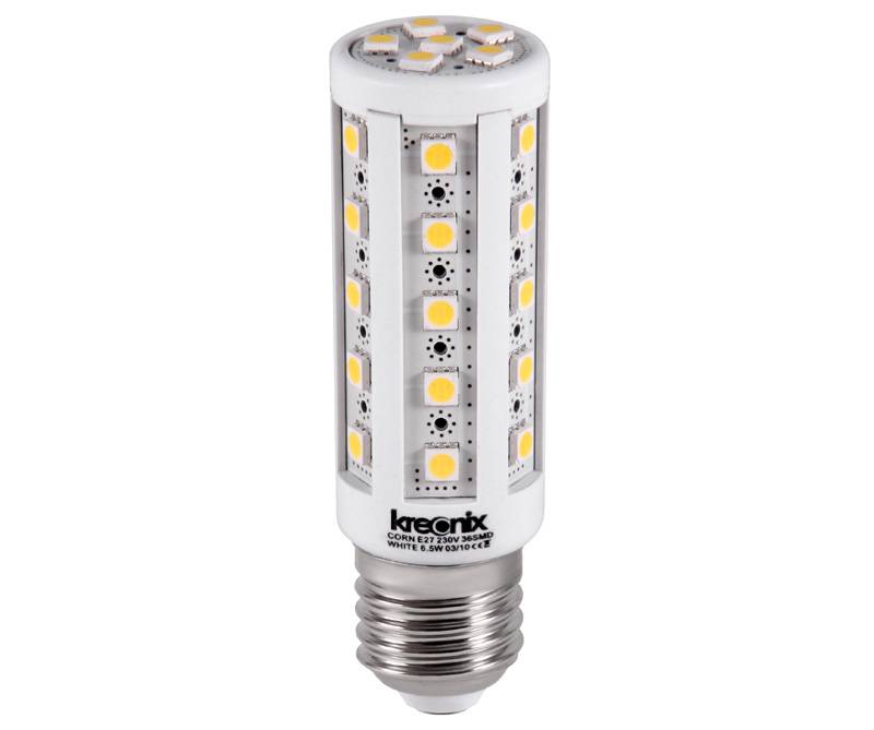
How is a 220 V LED lamp arranged?
This is a modern version of the LED lamp, which is produced using advanced technology. Here the LED is one-piece, there are several crystals, so there is no need to solder many contacts. As a rule, only two contacts are connected.
Table 1. The structure of a standard LED lamp
| Element | Description |
|---|---|
| Diffuser | An element in the form of a "skirt", which contributes to the uniform distribution of the light flux coming from the LED. Most often, this component is made of colorless plastic or matte polycarbonate. |
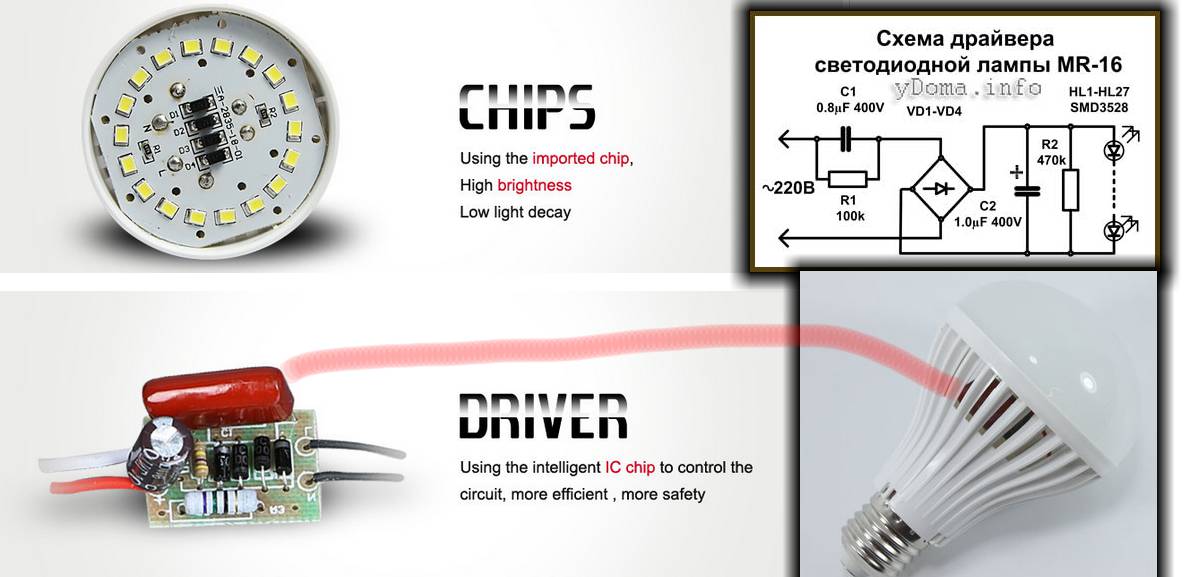
| LED chips | These are the main elements of modern light bulbs. Often they are installed in large quantities (more than 10 pieces). However, the exact number will depend on the power of the light source, the dimensions and the characteristics of the heat sink. |
| Dielectric plate | It is made on the basis of anodized aluminum alloys. After all, such material in the best way performs the function of heat removal to the cooling system. All this allows you to create a normal temperature for the smooth functioning of the chips. |
| Radiator (cooling system) | It helps to remove heat from the dielectric plate where the LEDs are located. For the manufacture of such elements, aluminum alloys are also used. Only here they pour it into special forms to get plates.This increases the area for heat dissipation. |
| Capacitor | Reduces the pulse that occurs when voltage is applied from the driver to the crystals. |
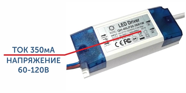
| Driver | A device that contributes to the normalization of the input voltage of the mains. Without such a small detail, it will not be possible to make a modern LED matrix. These elements can be either inline or inline. However, almost all lamps have built-in drivers that are located inside the device. |
| PVC base | This base is pressed against the base of the light bulb, thereby protecting electricians who are replacing the product from electric shock. |
| plinth | Required in order to connect the lamp to the socket. Most often it is made of durable metal - brass with an additional coating. This allows you to increase the life of the product and protect against rust. |
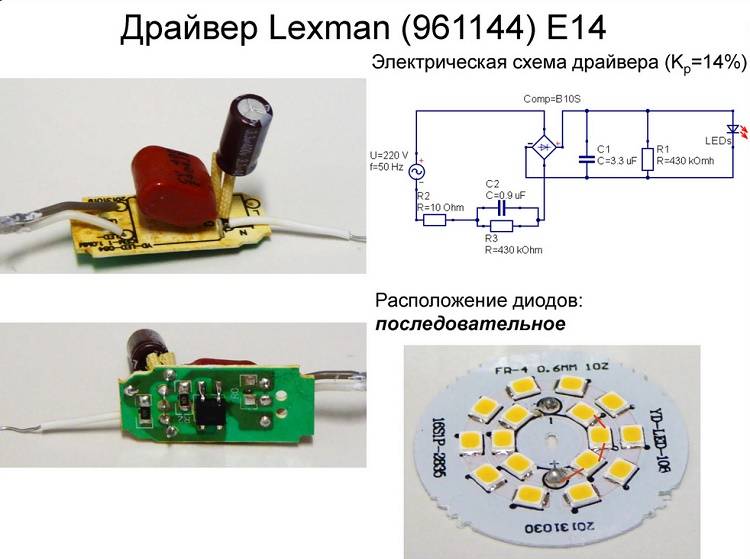
LED Bulb Driver
Another difference between LED lamps and other products is the location of the high heat zone. Other light sources spread heat throughout the outer part, while LED chips only contribute to the heating of the internal board. That is why it becomes necessary to install a radiator to quickly remove heat.


If there is a need to repair a lighting device with a failed LED, then it is completely replaced. In appearance, these lamps can be both round and in the form of a cylinder. They are connected to the power supply through the base (pin or threaded).
Conclusion
The cost of LED lamps is slowly but surely declining. However, the price still remains high. Not everyone can afford to change low-quality, but cheap, lamps or buy expensive ones.In this case, the repair of such lighting fixtures is a good way out.
If you follow the rules and precautions, then the savings will be a decent amount.
We hope that the information presented in today's article will be useful to readers. Questions that arise in the course of reading can be asked in the discussions. We will answer them as completely as possible. If someone had experience of similar works, we will be grateful if you share it with other readers.
And finally, by tradition, a short educational video on today's topic:


