- Darlington transistor
- FET driver
- DC interference protection
- Separate food
- Spark suppression DC circuits
- Filters
- Classification of solid state relays
- By the number of connected phases
- By type of operating current
- By design features
- By type of control scheme
- Purpose and types
- The main types of relays and their purpose
- Electromagnetic relays
- AC relay
- DC relay
- Electronic relay
- Working Principle of Solid State Relay
- Operating principle of solid state relay type SCR half-wave control
- Switching Types of Solid State Relays
- Key Indicators for Selecting Solid State Relays
- Recommendations for the selection of relays and operational nuances
- Indicative examples of relay selection in case of overcurrent
- Selection Guide
- DIY solid state relay
- Details and body
- The principle of operation of the starting relay
- Device diagram and connection to the compressor
- Closing contacts by means of an induction coil
- Regulation of current supply by a posistor
- Phase Control Solid State Relay
- What are the features?
Darlington transistor
If the load is very powerful, then the current through it can reach
several amps. For high power transistors, the coefficient $\beta$ can
be insufficient. (Moreover, as can be seen from the table, for powerful
transistors, it is already small.)
In this case, you can use a cascade of two transistors. The first
the transistor controls the current, which turns on the second transistor. Such
the switching circuit is called the Darlington circuit.
In this circuit, the $\beta$ coefficients of the two transistors are multiplied, which
allows you to get a very high current transfer coefficient.
To increase the turn-off speed of transistors, you can connect each
emitter and base resistor.
The resistances must be large enough not to affect the current
base - emitter. Typical values are 5…10 kΩ for voltages of 5…12 V.
Darlington transistors are available as a separate device. Examples
such transistors are shown in the table.
| Model | $\beta$ | $\max\ I_{k}$ | $\max\ V_{ke}$ |
|---|---|---|---|
| KT829V | 750 | 8 A | 60 V |
| BDX54C | 750 | 8 A | 100 V |
Otherwise, the operation of the key remains the same.
FET driver
If you still need to connect the load to the n-channel transistor
between the drain and the ground, then there is a solution. You can use ready
microcircuit - the driver of the upper shoulder. top - because the transistor
above.
Drivers of the upper and lower shoulders are also produced (for example,
IR2151) to build a push-pull circuit, but for simple switching
load is not required. This is necessary if the load cannot be left
"hang in the air", but it is required to pull it to the ground.
Consider the high-side driver circuit using the IR2117 as an example.
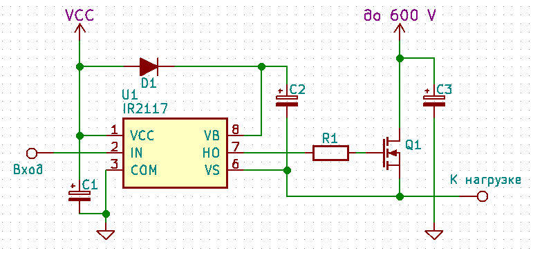
The circuit is not very complicated, and the use of the driver allows the most
efficient use of the transistor.
DC interference protection
Separate food
One of the best ways to protect against power interference is to power the power and logic parts from separate power supplies: a good low-noise power supply for the microcontroller and modules/sensors, and a separate one for the power part. In stand-alone devices, sometimes they put a separate battery to power the logic, and a separate powerful battery to the power part, because stability and reliability of operation is very important.
Spark suppression DC circuits
When the contacts open in the power supply circuit of an inductive load, a so-called inductive surge occurs, which sharply throws up the voltage in the circuit to the point that an electric arc (spark) can slip between the contacts of the relay or switch. There is nothing good in the arc - it burns out the metal particles of the contacts, because of which they wear out and become unusable over time. Also, such a jump in the circuit provokes an electromagnetic surge, which can induce strong interference in an electronic device and lead to malfunctions or even breakdown! The most dangerous thing is that the wire itself can be an inductive load: you have probably seen how a normal light switch in a room sparks. A light bulb is not an inductive load, but the wire leading to it has inductance.
To protect against self-induction EMF surges in a DC circuit, an ordinary diode is used, installed in anti-parallel load and as close as possible to it. The diode will simply short-circuit the emission to itself, and that's it:
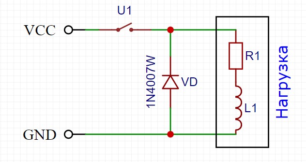 Where VD is a protective diode, U1 is a switch (transistor, relay), and R and L schematically represent an inductive load.
The diode must ALWAYS be installed when controlling an inductive load (electric motor, solenoid, valve, electromagnet, relay coil) using a transistor, that is, like this:

When controlling a PWM signal, it is recommended to install high-speed diodes (for example, 1N49xx series) or Schottky diodes (for example, 1N58xx series), the maximum diode current must be greater than or equal to the maximum load current.
Filters
If the power section is powered from the same source as the microcontroller, then power supply interference is inevitable. The easiest way to protect the MK from such interference is to supply capacitors as close as possible to the MK: electrolyte 6.3V 470 uF (uF) and ceramic at 0.1-1 uF, they will smooth out short voltage drops. By the way, an electrolyte with low ESR will cope with this task as efficiently as possible.

Even better, an LC filter, consisting of an inductor and a capacitor, will cope with noise filtering. The inductance must be taken with a rating in the region of 100-300 μH and with a saturation current greater than the load current after the filter. The capacitor is an electrolyte with a capacity of 100-1000 uF, again depending on the current consumption of the load after the filter. Connect like this, the closer to the load - the better:
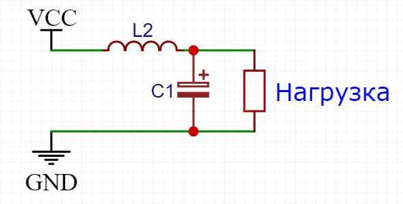
You can read more about calculating filters here.
Classification of solid state relays
Relay applications are diverse, therefore, their design features can vary greatly, depending on the needs of a particular automatic circuit. TSR is classified according to the number of connected phases, type of operating current, design features and type of control circuit.
By the number of connected phases
Solid state relays are used both in household appliances and in industrial automation with an operating voltage of 380 V.
Therefore, these semiconductor devices, depending on the number of phases, are divided into:
- single-phase;
- three-phase.
Single-phase SSRs allow you to work with currents of 10-100 or 100-500 A.They are controlled by an analog signal.


It is recommended to connect wires of different colors to a three-phase relay so that they can be connected correctly when installing equipment
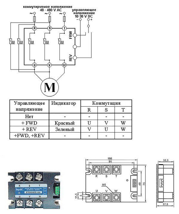
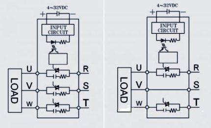
Three-phase solid-state relays are capable of passing current in the range of 10-120 A. Their device assumes a reversible principle of operation, which ensures the reliability of regulation of several electrical circuits at the same time.
Often, three-phase SSRs are used to power an induction motor. Fast fuses are necessarily included in its control circuit due to high starting currents.
By type of operating current
Solid state relays cannot be configured or reprogrammed, so they can only work properly within a certain range of network electrical parameters.
Depending on the needs, SSRs can be controlled by electrical circuits with two types of current:
- permanent;
- variables.
Similarly, it is possible to classify the TTR and by the type of voltage of the active load. Most relays in household appliances operate with variable parameters.
Direct current is not used as the main source of electricity in any country in the world, so relays of this type have a narrow scope
Devices with constant control current are characterized by high reliability and use voltage of 3-32 V for regulation. They withstand a wide temperature range (-30..+70°C) without significant change in characteristics.
Relays controlled by alternating current have a control voltage of 3-32 V or 70-280 V. They are characterized by low electromagnetic interference and high response speed.
By design features
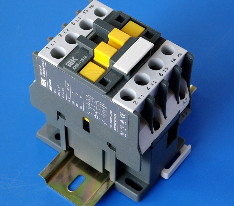
Solid state relays are often installed in the general electrical panel of an apartment, so many models have a mounting block for mounting on a DIN rail.
In addition, there are special radiators located between the TSR and the supporting surface. They allow you to cool the device at high loads, while maintaining its performance.
The relay is mounted on a DIN rail mainly through a special bracket, which also has an additional function - it removes excess heat during operation of the device
Between the relay and the heatsink, it is recommended to apply a layer of thermal paste, which increases the contact area and increases heat transfer. There are also TTRs designed for fastening to the wall with ordinary screws.
By type of control scheme
The principle of operation of an adjustable relay of technology does not always require its instantaneous operation.
Therefore, manufacturers have developed several SSR control schemes that are used in various fields:
- Zero control. This option for controlling a solid state relay assumes operation only at a voltage value of 0. It is used in devices with capacitive, resistive (heaters) and weak inductive (transformers) loads.
- Instant. It is used when it is necessary to actuate the relay abruptly when a control signal is applied.
- Phase. It involves the regulation of the output voltage by changing the parameters of the control current. It is used to smoothly change the degree of heating or lighting.
Solid state relays also differ in many other, less significant, parameters.
Therefore, when buying a TSR, it is important to understand the scheme of operation of the connected equipment in order to purchase the most appropriate adjustment device for it.
A power reserve must be provided, because the relay has an operational resource that is quickly consumed with frequent overloads.
Purpose and types
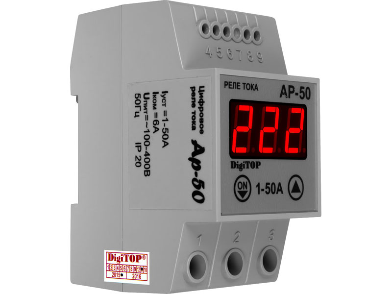
A current control relay is a device that responds to sudden changes in the magnitude of the incoming electric current and, if necessary, turns off the power to a certain consumer or the entire power supply system. Its principle of operation is based on comparing external electrical signals and instantaneous response if they do not match the operating parameters of the device. It is used to operate the generator, pump, car engine, machine tools, household appliances and more.
There are such types of devices of direct and alternating current:
- intermediate;
- Protective;
- Measuring;
- pressure;
- Time.
An intermediate device or a maximum current relay (RTM, RST 11M, RS-80M, REO-401) is used to open or close the circuits of a certain electrical network when a certain current value is reached. It is most often used in apartments or houses in order to increase the protection of household equipment from voltage and current surges.
The principle of operation of a thermal or protective device is based on controlling the temperature of the contacts of a certain device. It is used to protect devices from overheating. For example, if the iron overheats, then such a sensor will automatically turn off the power and turn it on after the device cools down.
A static or measuring relay (REV) helps to close the circuit contacts when a certain value of electric current appears.Its main purpose is to compare the available network parameters and the required ones, as well as quickly respond to their changes.


Pressure switch (RPI-15, 20, RPZH-1M, FQS-U, FLU and others) is necessary to control liquids (water, oil, oil), air, etc. It is used to turn off the pump or other equipment when the set indicators are reached pressure. Often used in plumbing systems and at car service stations.
Time delay relays (manufacturer EPL, Danfoss, also PTB models) are needed to control and slow down the response of certain devices when a current leakage or other network failure is detected. Such relay protection devices are used both in everyday life and in industry. They prevent the premature activation of the emergency mode, the operation of the RCD (it is also a differential relay) and circuit breakers. The scheme of their installation is often combined with the principle of including protective equipment and differentials in the network.
In addition, there are also electromagnetic voltage and current relays, mechanical, solid state, etc.
A solid state relay is a single-phase device for switching high currents (from 250 A), providing galvanic protection and isolation of electrical circuits. This is, in most cases, electronic equipment designed to quickly and accurately respond to network problems. Another advantage is that such a current relay can be made by hand.
By design, relays are classified into mechanical and electromagnetic, and now, as mentioned above, into electronic ones. Mechanical can be used in various working conditions, it does not require a complex circuit to connect it, it is durable and reliable.But at the same time, not accurate enough. Therefore, now its more modern electronic counterparts are mainly used.
The main types of relays and their purpose
Manufacturers configure modern switching devices in such a way that operation occurs only under certain conditions, for example, with an increase in the current strength supplied to the input terminals of the KU. Below we will briefly review the main types of solenoids and their purpose.
Electromagnetic relays
An electromagnetic relay is an electromechanical switching device, the principle of which is based on the effect of a magnetic field created by a current in a static winding on an armature. This type of KU is divided into actually electromagnetic (neutral) devices, which respond only to the value of the current supplied to the winding, and polarized ones, the operation of which depends both on the current value and on the polarity.
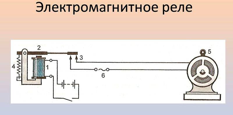 The principle of operation of the electromagnetic solenoid
The electromagnetic relays used in industrial equipment are in an intermediate position between high-current devices (magnetic starters, contactors, etc.) and low-current equipment. Most often this type of relay is used in control circuits.
AC relay
The operation of this type of relay, as the name implies, occurs when an alternating current of a certain frequency is applied to the winding. This AC switching device with or without phase zero control is a combination of thyristors, rectifier diodes and control circuits. AC relay can be made in the form of modules based on transformer or optical isolation.These KU are used in AC networks with a maximum voltage of 1.6 kV and an average load current of up to 320 A.
 Intermediate relay 220 V
Sometimes the operation of the mains and appliances is not possible without the use of an intermediate relay for 220 V. Usually, a KU of this type is used if it is necessary to open or open the oppositely directed contacts of the circuit. For example, if a lighting device with a motion sensor is used, then one conductor is connected to the sensor, and the other supplies electricity to the lamp.
 AC relays are widely used in industrial equipment and household appliances
It works like this:
- supplying current to the first switching device;
- from the contacts of the first KU, the current flows to the next relay, which has higher characteristics than the previous one and is able to withstand high currents.
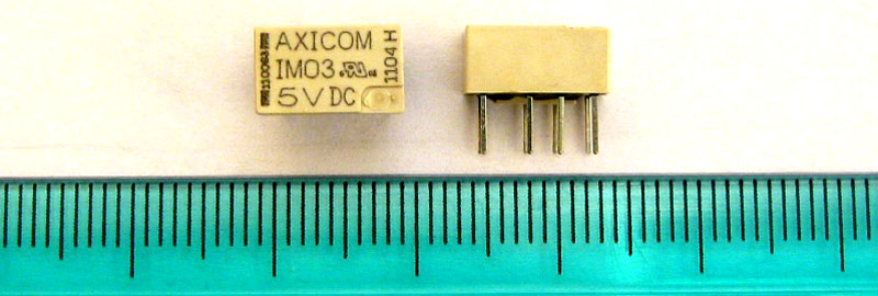 Relays become more efficient and compact every year.
The functions of the 220V small-sized AC relay are very diverse and are widely used as an auxiliary device in a wide variety of fields. This type of KU is used in cases where the main relay does not cope with its task or with a large number of controlled networks that are no longer able to serve the head unit.
The intermediate switching device is used in industrial and medical equipment, transport, refrigeration equipment, televisions and other household appliances.
DC relay
DC relays are divided into neutral and polarized. The difference between the two is that polarized DC capacitors are sensitive to the polarity of the applied voltage.The armature of the switching device changes direction of movement depending on the power poles. Neutral electromagnetic DC relays do not depend on the polarity of the voltage.
DC electromagnetic KU is mainly used when there is no possibility of connecting to the AC mains.
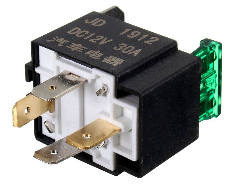 Four pin automotive relay
The disadvantages of DC solenoids include the need for a power supply and higher cost compared to AC.
This video demonstrates the connection diagram and explains how the 4 contact relay works:
Watch this video on YouTube
Electronic relay
 Electronic control relay in the device circuit
Having dealt with what a current relay is, consider the electronic type of this device. The design and principle of operation of electronic relays are practically the same as in electromechanical KU. However, to perform the necessary functions in an electronic device, a semiconductor diode is used. In modern vehicles, most of the functions of relays and switches are performed by electronic relay control units and at the moment it is impossible to completely abandon them. So, for example, a block of electronic relays allows you to control energy consumption, the voltage at the battery terminals, control the lighting system, etc.
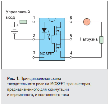
Working Principle of Solid State Relay
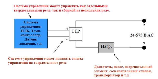
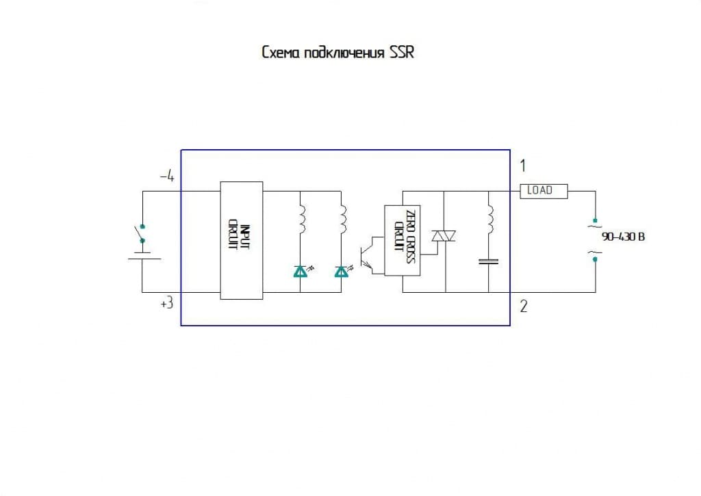
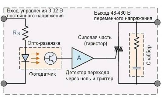
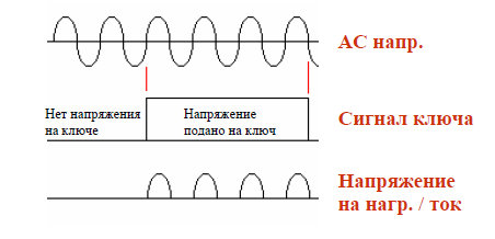
Rice. Number 3. Scheme of operation using a solid state relay. In the off position, when the input is 0V, the solid state relay prevents current from flowing through the load. In the on position, there is voltage at the input, current flows through the load.


The main elements of an adjustable AC voltage input circuit.
- The current regulator serves to maintain a constant current value.
- A full-wave bridge and capacitors at the input to the device serve to convert the AC signal to DC.
- Built-in optical isolation optocoupler, supply voltage is applied to it and input current flows through it.
- The trigger circuit is used to control the light emission of the built-in optocoupler, in case of interruption of the input signal, the current will stop flowing through the output.
- Resistors in series in a circuit.
There are two common types of optical decoupling used in solid-state relays - the seven-storer and the transistor.
The triac has the following advantages: the inclusion of a trigger circuit in the decoupling and its immunity to interference. The disadvantages include the high cost and the need for large amounts of current at the input to the device, which is necessary to switch the output.
Rice. No. 4. Scheme of a relay with a sevenistor.
Thyristor - does not need a large amount of current to switch the output. The disadvantage is that the trigger circuit is outside the isolation, which means a larger number of elements and poor protection against interference.
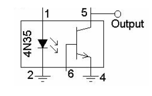
Rice. No. 5. Scheme of a relay with a thyristor.
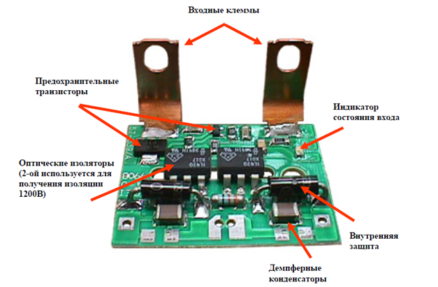
Rice. No. 6. Appearance and arrangement of elements in the design of a solid-state relay with transistor control.
Operating principle of solid state relay type SCR half-wave control
With the passage of current through the relay in only one direction, the amount of power is reduced by almost 50%. To prevent this phenomenon, two SCRs connected in parallel are used, located at the output (the cathode is connected to the anode of the other).
Rice. No. 7. Diagram of the operating principle of half-wave SCR control
Switching Types of Solid State Relays
- Control of switching actions when the current passes through zero.
Rice. No. 8. Relay switching when the current passes through zero.
Used for resistive loads in control and monitoring systems for heating devices. Use in slightly inductive and capacitive loads.
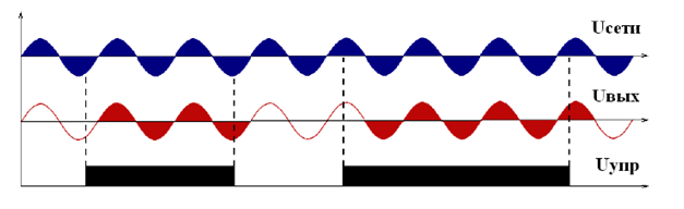
- Phase Control Solid State Relay
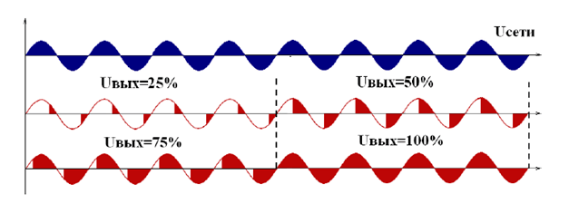
Fig. No. 9. Phase control scheme.
Key Indicators for Selecting Solid State Relays
- Current: load, starting, rated.
- Load type: inductance, capacitance or resistive load.
- Type of circuit voltage: AC or DC.
- Type of control signal.
Recommendations for the selection of relays and operational nuances
The current load and its nature are the main factor determining the choice. The relay is selected with a current margin, which includes taking into account the inrush current (it must withstand a 10-fold overcurrent and an overload for 10 ms). When working with a heater, the rated current exceeds the rated load current by at least 40%. When working with an electric motor, the current margin is recommended to be at least 10 times greater than the nominal value.
Indicative examples of relay selection in case of overcurrent
- Active power load, for example, a heating element - a margin of 30-40%.
- Electric motor of asynchronous type, 10 times the current margin.
- Lighting with incandescent lamps - 12 times the margin.
- Electromagnetic relays, coils - from 4 to 10 times the reserve.
Rice. No. 10. Examples of relay selection with active current load.
Such an electronic component of electrical circuits as a solid state relay is becoming an indispensable interface in modern circuits and provides reliable electrical isolation between all involved electrical circuits.
Write comments, additions to the article, maybe I missed something. Take a look at the sitemap, I will be glad if you find something else useful on my site.
Selection Guide
Due to electrical losses in power semiconductors, solid state relays heat up when the load is switched. This imposes a limitation on the amount of switched current. A temperature of 40 degrees Celsius does not cause a deterioration in the operating parameters of the device. However, heating above 60C greatly reduces the allowable value of the switched current. In this case, the relay may go into an uncontrolled mode of operation and fail.


Therefore, during long-term operation of the relay in nominal, and especially "heavy" modes (with long-term switching of currents above 5 A), the use of radiators is required. At increased loads, for example, in the case of a load of an "inductive" nature (solenoids, electromagnets, etc.), it is recommended to choose devices with a large current margin - 2-4 times, and in the case of controlling an asynchronous electric motor, 6-10 times current margin.
When working with most types of loads, the switching on of the relay is accompanied by a current surge of various duration and amplitude, the value of which must be taken into account when choosing:
- purely active (heaters) loads give the lowest possible current surges, which are practically eliminated when using relays with switching to "0";
- incandescent lamps, halogen lamps, when turned on, pass a current 7 ... 12 times more than the nominal;
- fluorescent lamps during the first seconds (up to 10 s) give short-term current surges, 5 ... 10 times higher than the rated current;
- mercury lamps give a triple current overload during the first 3-5 minutes;
- windings of electromagnetic relays of alternating current: current is 3 ... 10 times more than the rated current for 1-2 periods;
- windings of solenoids: current is 10 ... 20 times more than the nominal current for 0.05 - 0.1 s;
- electric motors: current is 5 ... 10 times more than the rated current for 0.2 - 0.5 s;
- highly inductive loads with saturable cores (transformers at idle) when switched on in the zero voltage phase: the current is 20 ... 40 times the nominal current for 0.05 - 0.2 s;
- capacitive loads when switched on in a phase close to 90°: the current is 20 ... 40 times the nominal current for a time from tens of microseconds to tens of milliseconds.
It will be interesting how it is used photorelay for street lighting?
The ability to withstand current overloads is characterized by the magnitude of the "shock current". This is the amplitude of a single pulse of a given duration (usually 10 ms). For DC relays, this value is usually 2–3 times the value of the maximum allowable direct current; for thyristor relays, this ratio is about 10. For current overloads of arbitrary duration, one can proceed from an empirical dependence: an increase in overload duration by an order of magnitude leads to a decrease in the allowable current amplitude. The calculation of the maximum load is presented in the table below.
Table for calculating the maximum load for a solid state relay.
The choice of rated current for a specific load should be in the ratio between the margin of the rated current of the relay and the introduction of additional measures to reduce starting currents (current-limiting resistors, reactors, etc.).
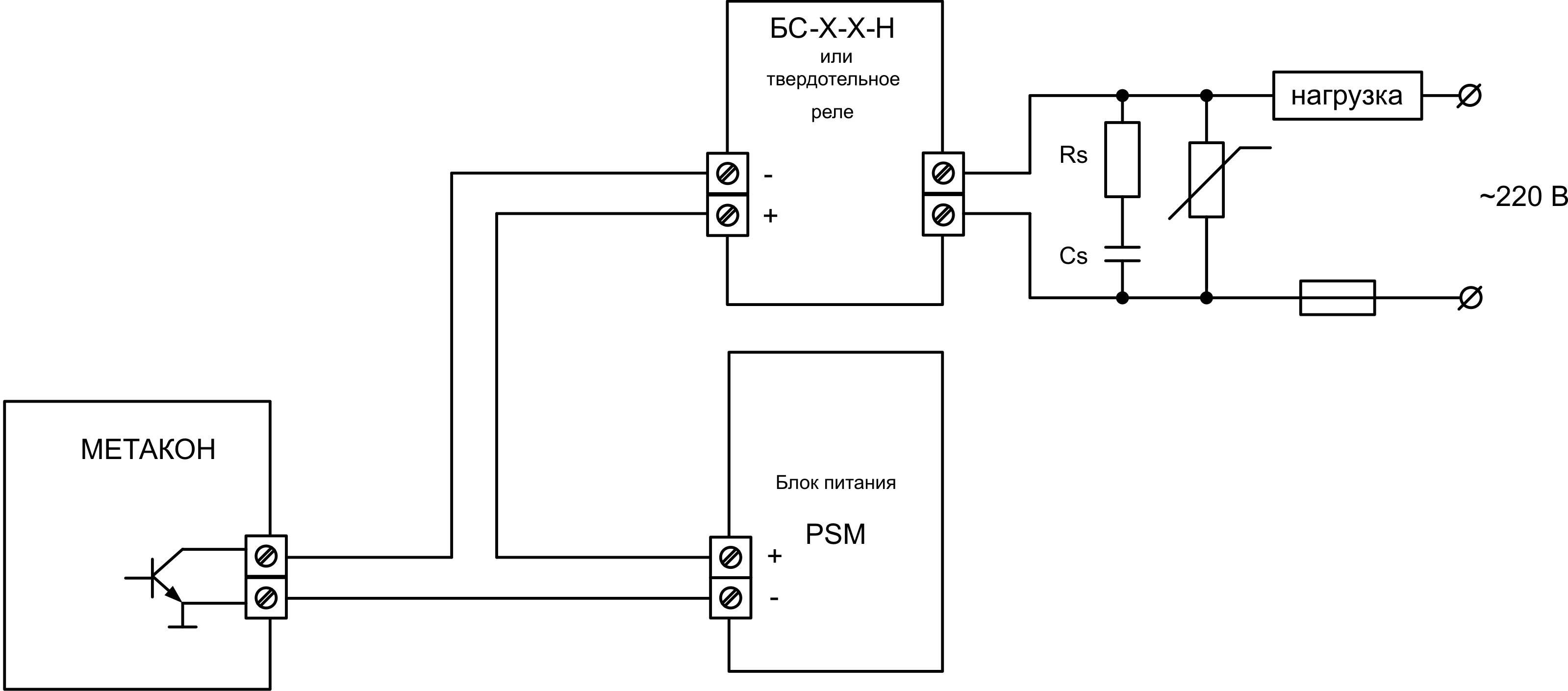
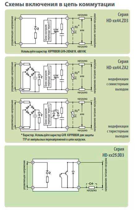
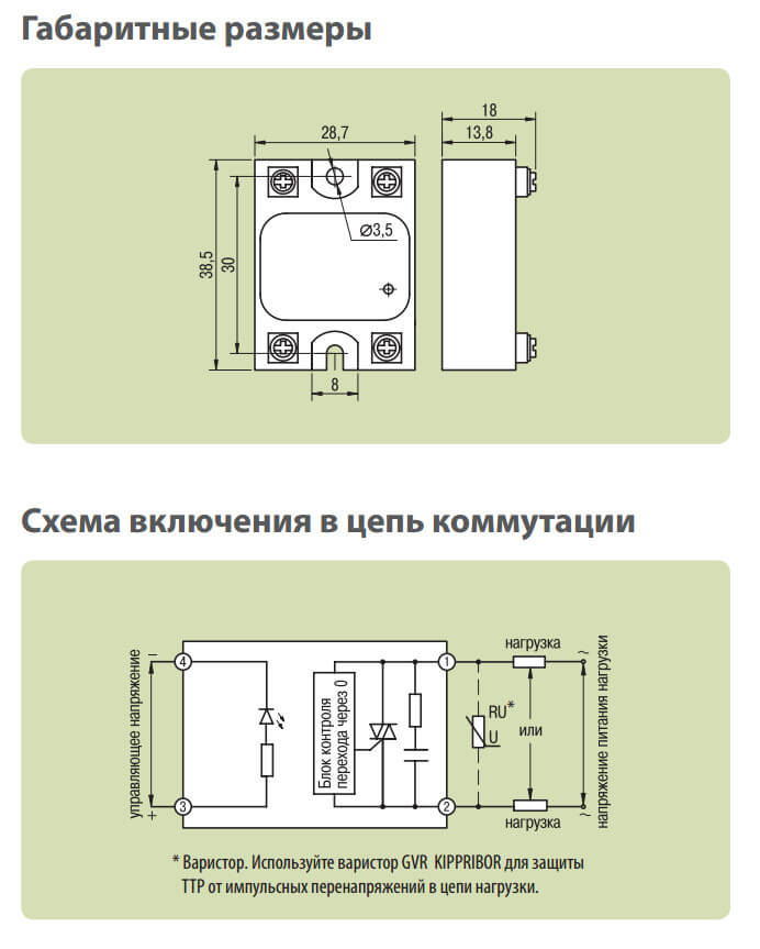
To increase the resistance of the device to impulse noise, an external circuit is placed in parallel with the switching contacts, consisting of a series-connected resistor and capacitance (RC circuit). For more complete protection against the source of overvoltage on the load side, it is necessary to connect protective varistors in parallel with each phase of the SSR.
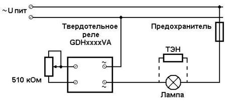
Scheme of connection of a solid state relay.
When switching an inductive load, the use of protective varistors is mandatory. The choice of the required value of the varistor depends on the voltage supplying the load, and is calculated by the formula: Uvaristor = (1.6 ... 1.9) x Uload.
The type of varistor is determined based on the specific characteristics of the device. The most popular domestic varistors are the series: CH2-1, CH2-2, VR-1, VR-2. The solid-state relay provides good galvanic isolation of the input and output circuits, as well as current-carrying circuits from the device's structural elements, so no additional circuit isolation measures are required.
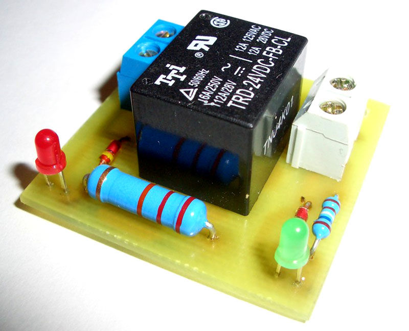
DIY solid state relay
Details and body
- F1 - 100 mA fuse.
- S1 - any low power switch.
- C1 - capacitor 0.063 uF 630 volts.
- C2 - 10 - 100 uF 25 Volts.
- C3 - 2.7 nF 50 Volts.
- C4 - 0.047 uF 630 Volts.
- R1 - 470 kOhm 0.25 Watt.
- R2 - 100 Ohm 0.25 Watt.
- R3 - 330 Ohm 0.5 Watt.
- R4 - 470 ohm 2 watts.
- R5 - 47 ohm 5 watts.
- R6 - 470 kOhm 0.25 Watt.
- R7 - Varistor TVR12471, or similar.
- R8 - load.
- D1 - any diode bridge for a voltage of at least 600 volts, or assembled from four separate diodes, for example - 1N4007.
- D2 is a 6.2 volt zener diode.
- D3 - diode 1N4007.
- T1 - triac VT138-800.
- LED1 – any signal LED.
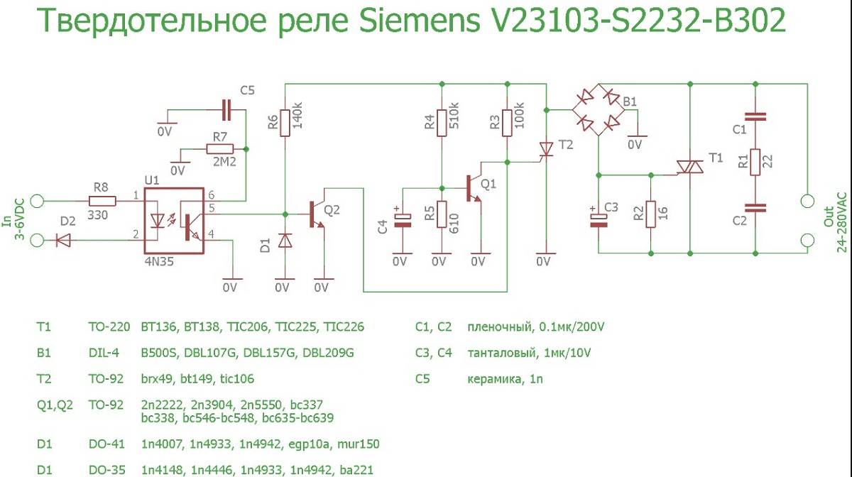
Modern electrical engineering and radio electronics are increasingly abandoning mechanical components that are of considerable size and subject to rapid wear. One area where this shows up the most is in electromagnetic relays. Everyone is well aware that even the most expensive relay, with platinum contacts, will fail sooner or later. Yes, and clicks when switching can be annoying. Therefore, the industry has established an active production of special solid-state relays.
Such solid state relays can be used almost anywhere, but they are currently still very expensive. Therefore, it makes sense to collect it yourself. Moreover, their schemes are simple and understandable. The solid state relay works like a standard mechanical relay - you can use a low voltage to switch a higher voltage.
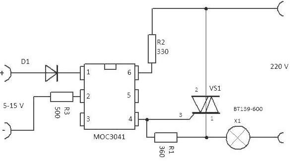
As long as there is no DC voltage present at the input (on the left side of the circuit), the TIL111 phototransistor is open. To increase the protection against false positives, the base of the TIL111 is supplied with an emitter through a 1M resistor. The base of the BC547B transistor will be at a high potential and thus remain open. The collector closes the control electrode of the TIC106M thyristor to minus, and it remains in the closed position. No current passes through the rectifier diode bridge and the load is turned off.
At a certain input voltage, say 5 volts, the diode inside the TIL111 lights up and activates the phototransistor. The BC547B transistor closes and the thyristor is unlocked. This creates a large enough voltage drop. on a 330 ohm resistor to switch the triac TIC226 to the on position. The voltage drop across the triac at that moment is only a few volts, so virtually all of the AC voltage flows through the load.
The triac is surge protected via a 100nF capacitor and a 47 ohm resistor. A BF256A FET was added to enable stable switching of a solid state relay with different control voltages. It acts as a current source. Diode 1N4148 is installed to protect the circuit in case of reverse polarity. This circuit can be used in various devices, with power up to 1.5 kW, of course, if you install the thyristor on a large radiator.
The principle of operation of the starting relay
Despite the large number of patented products from various manufacturers, the operation of refrigerators and the principles of operation of starting relays are almost the same. Having understood the principle of their action, you can independently find and fix the problem.
Device diagram and connection to the compressor
The electrical circuit of the relay has two inputs from the power supply and three outputs to the compressor. One input (conditionally - zero) passes directly.
Another input (conditionally - phase) inside the device is split into two:
- the first passes directly to the working winding;
- the second passes through the disconnecting contacts to the starting winding.
If the relay does not have a seat, then when connecting to the compressor, you must not make a mistake with the order of connecting the contacts. The methods used on the Internet to determine the types of windings using resistance measurements are not generally correct, since for some motors the resistance of the starting and working windings is the same.
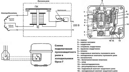 The electrical circuit of the starter relay may have minor modifications depending on the manufacturer. The figure shows the connection diagram of this device in the Orsk refrigerator
Therefore, it is necessary to find documentation or disassemble the refrigerator compressor to understand the location of the through contacts.
This can also be done if there are symbolic identifiers near the outputs:
- “S” - starting winding;
- "R" - working winding;
- “C” is the common output.
Relays differ in the way they are mounted on the refrigerator frame or on the compressor. They also have their own current characteristics, therefore, when replacing, it is necessary to select a completely identical device, or better, the same model.
Closing contacts by means of an induction coil
The electromagnetic starting relay works on the principle of closing a contact to pass current through the starting winding. The main operating element of the device is a solenoid coil connected in series with the main motor winding.
At the time of compressor start, with a static rotor, a large starting current passes through the solenoid. As a result of this, a magnetic field is created that moves the core (armature) with a conductive bar installed on it, closing the contact of the starting winding. The acceleration of the rotor begins.
With an increase in the number of revolutions of the rotor, the amount of current passing through the coil decreases, as a result of which the magnetic field voltage decreases. Under the action of a compensating spring or gravity, the core returns to its original place and the contact opens.
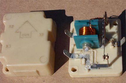
On the cover of the relay with an induction coil there is an arrow “up”, which indicates the correct position of the device in space.If it is placed differently, then the contacts will not open under the influence of gravity
The compressor motor continues to operate in the mode of maintaining the rotation of the rotor, passing current through the working winding. The next time the relay will work only after the rotor stops.


Regulation of current supply by a posistor
Relays produced for modern refrigerators often use a posistor - a type of thermal resistor. For this device, there is a temperature range, below which it passes current with little resistance, and above - the resistance increases sharply and the circuit opens.
In the starting relay, the posistor is integrated into the circuit leading to the starting winding. At room temperature, the resistance of this element is negligible, so when the compressor starts, the current passes unhindered.
Due to the presence of resistance, the posistor gradually heats up and when a certain temperature is reached, the circuit opens. It cools down only after the current supply to the compressor is interrupted and again triggers a skip when the engine is turned on again.
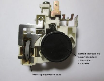 The posistor has the shape of a low cylinder, so professional electricians often call it a “pill”
Phase Control Solid State Relay
Although solid state relays can perform direct zero-crossing load switching, they can also perform much more complex functions with the help of digital logic circuits, microprocessors, and memory modules. Another excellent use for a solid state relay is in lamp dimmer applications, whether at home, for a show or a concert.
Solid state relays with non-zero turn on (momentary turn on) turn on immediately after the input control signal is applied, unlike the zero crossing SSR which is higher and waits for the next zero crossing point of the AC sine wave. This random fire switching is used in resistive applications such as lamp dimmers and in applications where the load only needs to be applied during a small part of the AC cycle.
What are the features?
When creating a solid-state relay, it was possible to exclude the appearance of an arc or sparks in the process of closing / opening a contact group. As a result, the service life of the device has increased several times. For comparison, the best versions of standard (contact) products can withstand up to 500,000 switching. There are no such restrictions in the TTRs under consideration.
The cost of solid state relays is higher, but the simplest calculation shows the benefits of their use. This is due to the following factors - energy savings, long service life (reliability) and the presence of control using microcircuits.
The choice is wide enough to pick up the device taking into account the tasks and the current cost. Commercially available are both small appliances for installation in household circuits and powerful devices used to control motors.
As noted earlier, SSRs differ in the type of switched voltage - they can be designed for constant or variable I. This nuance must be taken into account when choosing.
POPULAR WITH READERS: Do-it-yourself hidden wiring in a wooden house, step by step instructions
The features of solid-state models include the sensitivity of the device to load currents.If this parameter exceeds the permissible norm by 2-3 or more times, the product breaks.
To avoid such a problem during operation, it is important to carefully approach the installation process and install protective devices in the key circuit. In addition, it is important to give preference to switches that have a working current of two or three times the switching load.
But that's not all
In addition, it is important to give preference to switches that have a working current of two or three times the switching load. But that's not all
For additional protection, it is recommended to provide fuses or circuit breakers in the circuit (class "B" is suitable).


