- lit the arcs
- Preparing to work with the inverter
- Use of protective equipment
- Three-phase AC
- Energy and power of electric current
- What is welding?
- Choosing a household welding machine
- Courses for welders
- Basics of electricity
- Electrical resistance of conductors
- Differences between direct and reverse polarity when welding with an inverter
- Inverter welding of thin metal
lit the arcs
Welding for beginners, first of all, involves the ability to strike an arc, and also correctly tear off the electrode from the part after that. The Welding Tutorial recommends two ways to start the arc. The first of them is carried out by touching, and the second by striking.
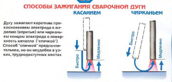
Touch or scratch the surface of the part to be welded. You can first practice doing this with an electrode not connected to the welding machine. The touch should be light, after which the electrode should be quickly retracted. The striking is reminiscent of the well-known making of fire with the help of matches and a matchbox.
If the arc is ignited by touch, then the electrode should be held as perpendicular to the surface as possible, and lifted up by only a few millimeters. Fast retraction is a guarantee that the electrode does not stick to the surface of the workpiece. If this trouble does happen, then it is necessary to tear off the adhered electrode, sharply deflecting it to the side.After that, the ignition of the arc should be continued.
Welding for dummies recommends using the second method to ignite the arc - by striking. To do this, it is enough to use the imagination, imagining that the striking occurs not with an electrode, but with an ordinary match. In hard-to-reach places, this method is inconvenient, but this has nothing to do with novice welders, since they will learn for the time being on simple joints.
You will have to return to ignition of the arc more than once after the electrode has completely burned out and it will have to be replaced with a new one.
Since the initial part of the seam will be completed, some rules will have to be applied when re-igniting. First, the welding seam must be freed from the slag formed during the work with the previous electrode. The arc should be ignited directly behind the crater.
Preparation for welding is not completed by ignition of the arc. Then the weld pool is to be formed. To do this, the electrode will have to make a turn several times around the point from which it is planned to start welding the seam.
Welding and their training includes the ability to hold the arc after it has been ignited. For the training to be successful, the current on the welding machine should be set to 120 amperes. This will not only make it easier to strike the arc, but also reduce the likelihood of flame extinction, as well as control of the filling of the weld pool.
You can understand how the bath control can take place by gradually lowering the current value. In this case, it is necessary to increase the distance between the end of the electrode and the part so that it does not stick to its surface.
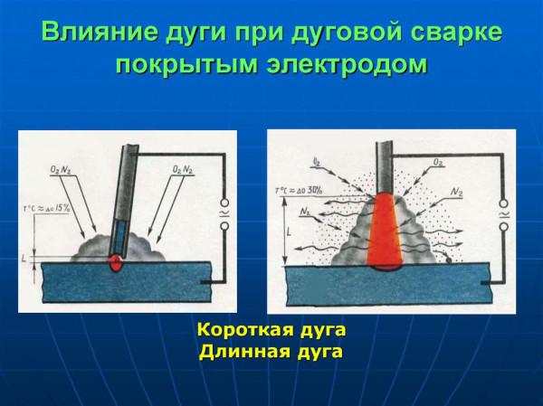
A novice welder should be prepared for the fact that as the arc length increases, metal spatter will also increase. When welding, the length of the electrode used will invariably decrease as it burns out, therefore, in order to maintain the magnitude of the arc, it should be brought closer to the surface of the product at an appropriate distance.
If the distance becomes insufficient, then the metal will not warm up well and the seam will turn out to be too convex, and its edges will remain unmelted.
However, this distance should not be made too large, since in this case peculiar jumps of the arc will occur, which will lead to the formation of an ugly seam with a shapeless shape.
Welding technology to obtain a satisfactory result requires the selection of the correct distance between the electrode and the workpiece. There is a hint - the optimal length of the arc will be its size, not exceeding the diameter of the electrode, including its coating with a coating. On average, this is equal to three millimeters.
Preparing to work with the inverter
When switching on for the first time, as well as when moving the welding inverter to a new place of work, it is necessary to check the insulation resistance between the case and current-carrying parts, and then connect the case to ground. If the inverter has been in operation for a long time, before starting welding, it is imperative to inspect it for dust accumulation in the internal space. In case of increased dustiness, clean all power elements and welding control units using compressed air with moderate pressure. For the unhindered operation of the forced ventilation system of the apparatus, free space must be created around it at a distance of at least half a meter.It is forbidden to cook with inverter welding devices near the places of work of grinders and cut-off machines, as they create metal dust that can damage the power unit and inverter electronics. In the case of outdoor welding, the machine must be protected from direct splashes of water and sunlight. The welding inverter must be installed on a horizontal surface (or at an angle not exceeding the value specified in the passport).

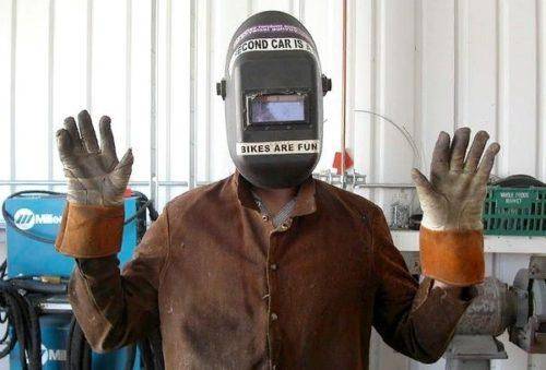
Use of protective equipment
When carrying out welding work, the greatest danger is the likelihood of electric shock, burns from flying drops of molten metal and light exposure to the retina of the eye by the radiation of an electric arc. In addition, mechanical injuries and inhalation of gases released during the welding process are possible. Therefore, any novice welder who decides to master the welding inverter, in addition to the device itself, must purchase a set of personal protective equipment, as well as carefully study the safety regulations when performing welding work. The standard set of protective equipment for a welder includes a mask and spark-resistant gloves, as well as overalls and shoes made of non-combustible and non-consumable materials. In addition, during welding with an inverter, a special respirator may be required, and workpieces and seams must be cleaned with goggles.
Three-phase AC
In industry, as a rule, three-phase alternating current is used. This current is obtained using three-phase alternators.A simplified device for a three-phase generator is shown in the figure below.
The phases of a three-phase current are usually denoted by the first three letters of the Latin alphabet: A, B and C.
Schematically, the figure above can be represented as follows:
In three-phase AC circuits, the wires marked with the numbers 1, 2 and 3 are combined into one wire, called zero or neutral.
In full form, the three-phase current supply network diagram and its parameters are presented below.
As can be seen from the figure shown above, during rotation, the rotor induces an electromotive force (EMF) first in the phase A coil, then in the phase B coil, and then in the phase C coil. Thus, the voltage curves at the output terminals of these coils are, as it were, shifted with each other at an angle of 120º.
Energy and power of electric current
The electric current, flowing through the conductors, does work, which is estimated by calculating the energy of the electric current (Q), which was spent in this case. It is equal to the product of the current strength (I) and the voltage (U) and the time (t) during which the current passes:
Q=I*U*t
The ability of the current to do work is estimated by the power, which is the energy received by the receiver or given off by the current source per unit time (per 1 second) and is calculated as the product of the current strength (I) and voltage (U):
P=I*U
The unit of measure of power is watts (W) - the work done in an electrical circuit at a current strength of 1 A and a voltage of 1 V for 1 s.
In technology, power is measured in larger units: kilowatts (kW) and megawatts (MW): 1 kW = 1,000 W; 1 MW = 1,000,000 W.
What is welding?
The classic definition of the welding process is: "The process of creating inseparable connections through the establishment of interatomic relationships between parts that are connected during their heating and (and) plastic deformation." Keeping in mind the phenomenon of diffusion, it is known that in hot water the process of interpenetration is accelerated. Welding is very similar to diffusion, only the heating of the two parts occurs with the help of a high-temperature electric arc generated by the welding machine. Under its influence, melting and interpenetration of materials of parts occurs. A weld appears, which consists of the materials of both parts and other chemicals that were introduced by the consumable electrode (element of the welding machine). There are many versions about the strength of this seam, someone believes that 1 cm of the weld can withstand 100 kg, someone claims that it is more, but everyone agrees on one thing: the strength of the weld is not inferior to the strength of the base metals of the parts. In addition to defining the main concept, the theoretical foundations of welding work also include the physical and chemical processes that occur during welding.


What happens during welding in terms of chemistry and physics?
Consider the scheme of the welding process on the example of electric arc welding.
Electric voltage is applied to the electrode and to the part, but only of different polarity. As soon as the electrode is brought to the part, an electric arc is immediately ignited, melting everything in its field of action. At this time, the electrode material moves drop by drop into the weld pool.In order for the process not to stop, and this will happen when the electrode is stationary, it is necessary to move the electrode in three directions at once: transverse, translational and stably vertical (Fig. 2).
After all the manipulations, the welder removes the welding machine and the weld pool, solidifying, forms the same welding seam. This is the kind of chemistry and physics that happens during electric arc welding. Naturally, with other types of welding, the mechanisms will be different. For example, in the above form, the main thing is the melting mechanism, and during pressure welding, the surfaces to be welded are not only heated, but also squeezed with the help of sedimentary pressure. Let us consider in more detail the classification of types of welding.
Choosing a household welding machine
There are a lot of types of welding today. But most of them are designed for special work or are designed for industrial scale. For domestic needs, it is unlikely that you will need to master a laser installation or an electron beam gun. And gas welding for beginners is not the best option.
The easiest way to melt metal to join parts is to point it to the high temperature of an electric arc that occurs between elements with different charges.

Electric arc
It is this process that is provided by electric arc welding machines operating on direct or alternating current:
Welding transformer cooks with alternating current. For a beginner, such a device is hardly suitable, since it is more difficult to work with it because of the “jumping” arc, which requires considerable experience to control.Other disadvantages of transformers include a negative impact on the network (causes power surges that can lead to breakdown of household appliances), loud noise during operation, impressive dimensions of the device and heavy weight.

welding transformer
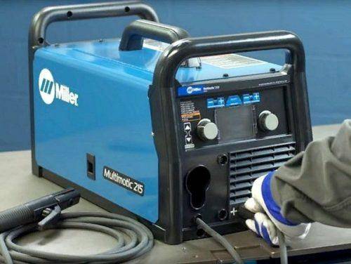
An inverter has many advantages over a transformer. It causes an electric arc with direct current, it does not “jump”, so the welding process is more calm and controlled for the welder and without consequences for home appliances. In addition, the inverters are compact, lightweight and virtually silent.

Welding inverter
Courses for welders
Welding can be mastered in special courses. Welding training is divided into theory and practical training. You can study in person or remotely. The courses teach welding technology for beginners and other important wisdom. Important is the opportunity to learn how to cook by welding in practical classes under the supervision of a teacher. Students are given an idea about the available equipment for welding, the choice of electrodes, safety rules.
You can study individually or with a group. Each option has its own advantages. When studying individually, you can master only those knowledge that can be useful in the future. But when studying in a group, there is an opportunity to hear the analysis of the mistakes of their fellow students and thus acquire additional knowledge.
After completing the courses and passing the exams confirming the acquired knowledge and practical skills, a certificate of the approved sample is issued.
Basics of electricity
Electric current in metal conductors is a directed movement of free electrons along a conductor included in an electrical circuit. The movement of electrons in an electrical circuit occurs due to the potential difference at the terminals of the source (i.e. its output voltage).


Electric current can only exist in a closed electrical circuit, which must consist of:
- current source (battery, generator, ...);
- consumer (incandescent lamp, heating devices, welding arc, etc.);
- conductors connecting the power source to the consumer of electrical energy.
Electric current is usually denoted by the Latin uppercase or lowercase letter I (i).
The unit of measure for the strength of an electric current is an ampere (denoted by A).
The current strength is measured using an ammeter, which is included in the break in the electrical circuit.
Unlike electric current, voltage at the terminals of a power source or circuit elements exists regardless of whether the electrical circuit is closed or not.
Voltage is usually denoted by the Latin uppercase or lowercase letter U (u).
The unit of measure for voltage is volts (denoted V).
The voltage value is measured using a voltmeter, which is connected in parallel to the section of the electrical circuit on which the measurement is made.
Wires and pantographs included in an electrical circuit resist the passage of current.
Electrical resistance is usually denoted by the Latin capital letter R.
The unit of measurement for the resistance of an electrical circuit is ohm (denoted by Ohm).
The value of electrical resistance is measured with an ohmmeter, which is connected to the ends of the measured section of the circuit, while no current should flow through the measured section of the circuit.
An electrical circuit can be constructed in such a way that the beginning of one resistance is connected to the end of another. Such a connection is called serial.
In an electrical circuit with a series connection of resistances (consumers), the following dependencies exist.
The total resistance of such a circuit is equal to the sum of all these individual resistances:
R=R1 + R2 + R3
Since the current passes through all the resistances in series one after the other, its value is the same in all sections of the circuit.
The sum of the voltage drops in all sections of the electrical circuit is equal to the voltage at the source terminals:
Uist = Uab + Ucd
The magnitude of the voltage drop in a separate section of the electrical circuit is equal to the product of the magnitude of the current in the circuit and the electrical resistance of this section.
If in an electric circuit all the beginnings of the resistances are connected on one side, and all their ends on the other, then such a connection is called parallel.
The total resistance of such a circuit is less than the resistance of any of its constituent branches.
For a circuit with two resistors connected in parallel, the total resistance is calculated by the formula:
R=R1 * R2 / (R1 + R2)
Each additional resistance in parallel connection reduces the total resistance of such a circuit. The ballast rheostat uses a parallel connection of resistances. Therefore, when each additional “knife” is turned on, the total resistance of the ballast rheostat decreases, and the current in the circuit increases.

In the section of the circuit with parallel connection, the current branches, passing simultaneously through all the resistances:
i = i1 +i2 +i3
All resistances in a parallel circuit are under the same voltage:
Uab = U1 = U2 = U3
Electrical resistance of conductors
The resistance of a conductor depends on:
- from the length of the conductor - with an increase in the length of the conductor, its electrical resistance increases;
- from the cross-sectional area of \u200b\u200bthe conductor - with a decrease in the cross-sectional area, the resistance increases;
- from the temperature of the conductor - with increasing temperature, the resistance increases;
- on the coefficient of resistivity of the conductor material.
The greater the resistance of the conductor to the passage of electric current, the more energy the free electrons lose, and the more the conductor (which is usually an electrical wire) heats up.
For each cross-sectional area of the wire, there is a permissible current value. If the current is greater than this value, then the wires can heat up to a high temperature, which, in turn, can cause ignition of the insulating coating.
Maximum permissible current values for different sections of copper insulated welding wires are shown in the table below:
| Wire cross section, mm2 | 16 | 25 | 35 | 50 | 70 |
| Maximum allowable current, A | 90 | 125 | 150 | 190 | 240 |
Remember! The amount of current in amperes (I) per square millimeter of wire cross-sectional area (S) is called current density (j):
j (A / mm2) = I (A) / S (mm2)
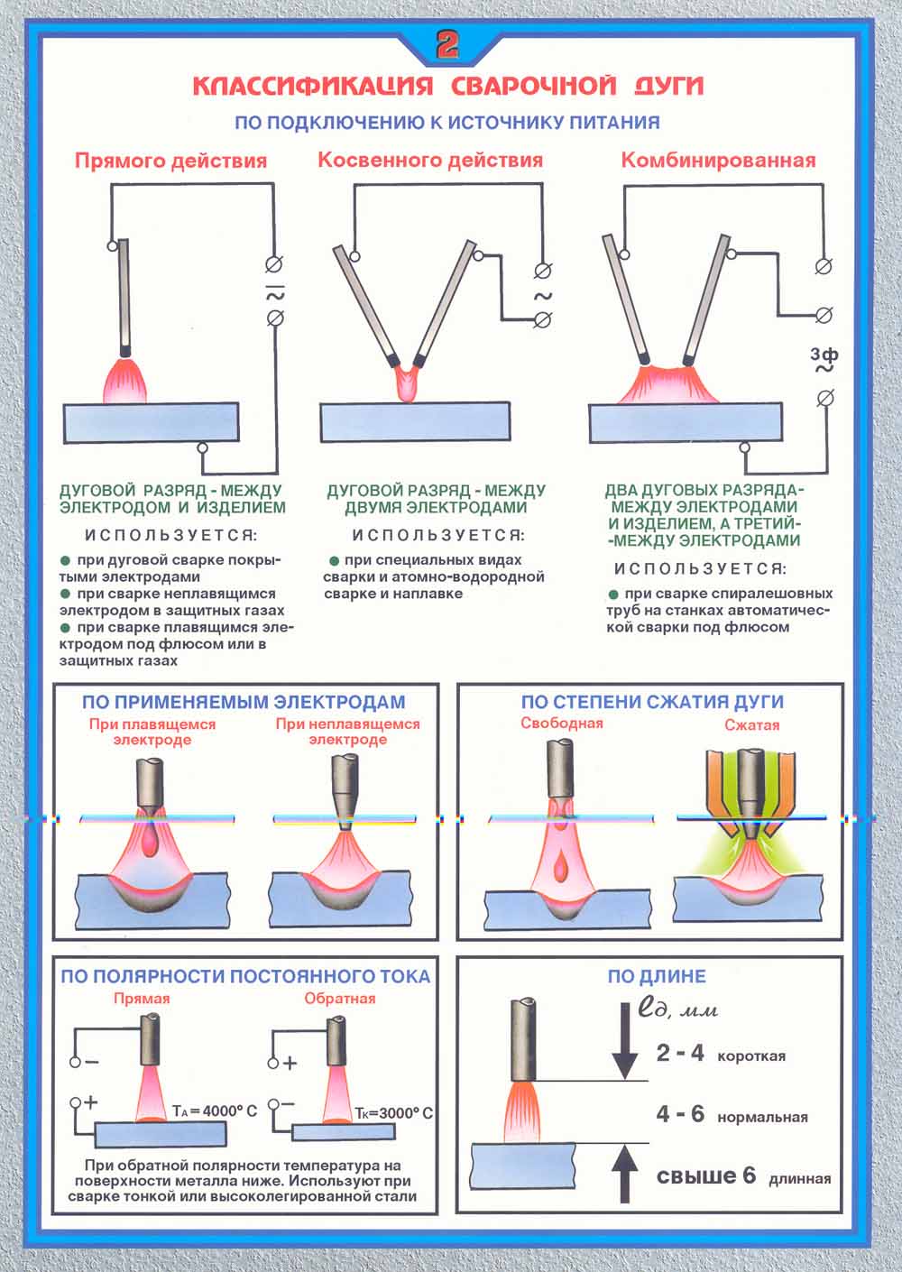
Differences between direct and reverse polarity when welding with an inverter
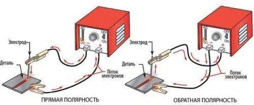
When welding with reverse polarity, the electrode holder is connected to the positive contact of the inverter, and the ground terminal is connected to the negative one.In this case, the detachment of electrons occurs from the metal of the workpiece, and their flow is directed towards the electrode. As a result, most of the thermal energy is released on it, which makes it possible to weld with an inverter with limited heating of the welded part. This mode is used when welding parts made of thin metal, stainless steels and metals with low resistance to elevated temperatures. In addition, reverse polarity is used when it is necessary to increase the melting rate of the electrode, and also when parts are welded with an inverter in a gaseous environment or using fluxes.
Inverter welding of thin metal
The capabilities of the inverter are fully realized when welding rolled metal with a thickness of less than 2 mm. Welding of such materials is carried out at low welding currents and requires high stability of the welding process, which is easily realized when using a device with an inverter power source. Thin metal sheets are easy to burn through when a short circuit occurs in the welding arc. To prevent this phenomenon, the inverters have a special function that automatically reduces the amount of current for the duration of a short circuit. Another useful feature of inverters is the selection of optimal parameters during arc ignition, which makes it possible to avoid lack of penetration and burns in the initial section of the weld. In addition, during the welding process, the inverter is able to adaptively maintain the desired value of the operating current with fluctuations in the size of the welding arc.