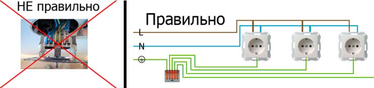
- Installation of branches in the socket
- Socket and switch connection diagram: loop, series, parallel
- Electrical outlet device
- Types of devices and their features
- Main popular types
- Tasks for Parallel connection of conductors with solutions
- How to connect the outlet correctly - detailed instructions
- Necessary tools and materials
- wall chasing
- How to connect a ground outlet
- How to connect a double socket
- Mixed connection and grounding in series connection
- Combined method
- Power connection procedure
- How to connect the socket correctly
- Compliance with safety regulations when installing sockets
- Open and closed wiring
- Open wiring - advantages and disadvantages
- Hidden wiring - pros and cons
- Pros and cons
- Parallel connection specifics
- Connection methods
- Conclusion
Installation of branches in the socket
Wiring can run inside the walls or along their surface. The first option is simple in execution, but loses in aesthetics. Hidden wiring provides for wall decoration after installation. However, when it becomes necessary to repair the electrical network, it is necessary to destroy the walls.
Connecting devices to the power cable must be safe and secure. Each socket must have an enclosure to protect against electric current.Mounted have their own box. To install the built-in sockets are used. They are made of dielectric materials, securely fix the device in the wall, prevent moisture ingress and are fireproof.
Grounding is installed in each socket, there is enough space for laying wires. This method is considered reliable and guarantees protection. It is indispensable when additional installation of several outlets is required. Excludes carrying out large-scale works. Use it for light loads in an apartment or house, under normal conditions.
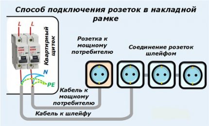
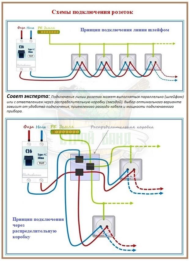
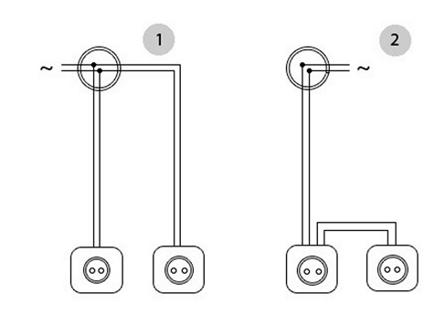
Socket and switch connection diagram: loop, series, parallel
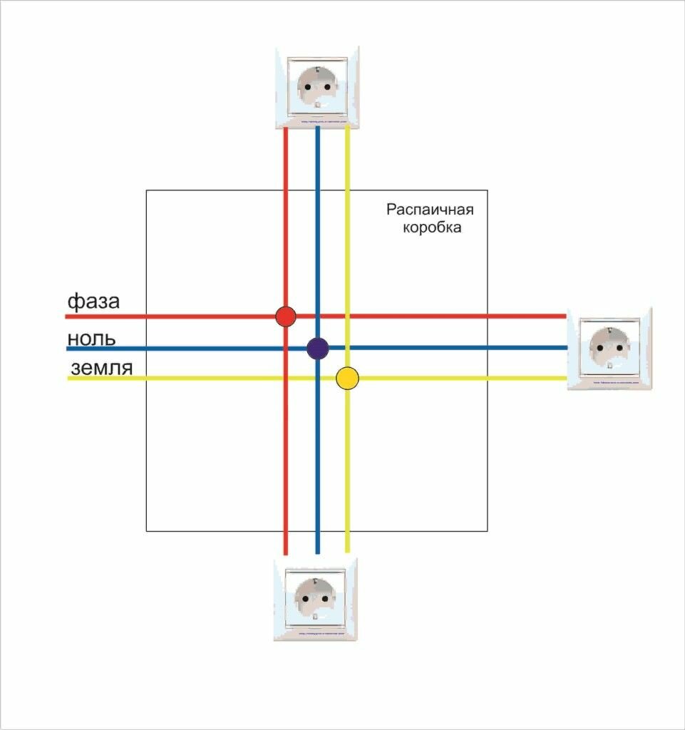
Let's look at how to connect an outlet or a block of several units. You can connect electrical outlets in parallel through a junction box or using terminals, this method is also called a daisy chain connection. When connecting electrical outlets with a loop, the cable is connected to the first unit of the block, and the cable for the next block is powered from the last one. Daisy-chaining requires mandatory, independent socket disconnects. To do this, the conductors are connected to neutral conductors through terminals or soldering. Zero and phase are connected to the first electrical outlet. A clamp is placed on the ground wire, from which a ground wire is connected to each of the units. To connect the second socket block, you need to connect the phase and the working zero from the last unit of the first block, and the ground wire to the compression.
Now consider connecting a conventional single-gang switch.To do this, we connect the phase wire to the switch using the clamp marked with the English "L" or the arrow "out", we connect zero to the clamp with the arrow "in" or the letter "N". Both wires are securely fastened. Since grounding is not used in the switches, we cut off the excess wire and isolate it.
Another pertinent question is: How connect the switch from the socket"? To do this, it is better to use a block consisting of an electrical outlet and one or more switches. A new cable is laid from the junction box. On one core of the cable, the phase is directed to the switch, and on the other, the working "zero" to the outlet. The rest of the wires pass to the lamps through the switches. From the junction box to the fixtures, 3-core wires are laid (zero, ground and phase).
Electrical outlet device
Almost any master had to deal with connecting the outlet. At first glance, this procedure is very simple, but there are many nuances hidden under it. So that a self-connected outlet does not become a source of problems, you need to understand the principle of its operation. It consists of the following components:
- Decorative cap with fixed screw.
- Socket box. To fasten the element inside the mounting hole, it has paws, with the help of which the insert is attached to the hole, the pads in which the contacts are movable are more difficult to install, but thanks to their design it is possible to adjust the position in terms of inclination and height. It is advisable to choose models with two-pronged paws. Compared to single teeth, they are much more reliable.
- Complete contact box. The terminals can be connected in various ways, as with contact screws directly, or as a single unit.Two contacts, zero and phase, as well as grounding which is located separately.
Types of devices and their features
There are quite a few varieties of plug sockets and blocks. Each type has its own design features and purpose.
- Hidden appliances are mounted directly into the wall - in special sockets.
- Open devices are produced for those apartments where the wiring is not hidden in the wall.
- Retractable socket blocks are mounted on a table or other furniture. Their convenience is that after operation, the devices are easy to hide from prying eyes and playful children's hands.
The devices differ in the method of clamping the contacts. It is screw and spring. In the first case, the conductor is fixed with a screw, in the second - with a spring. The reliability of the latter is greater, but it is not so easy to find them on sale. Devices are fixed on the walls in three ways - with serrated edges, self-tapping screws or a special plate - a support that facilitates both installation and dismantling of the outlet.
In addition to conventional, inexpensive devices, there are models equipped with grounding contacts. These petals are located in the upper and lower parts, a ground wire is attached to them. To ensure safety, outlets equipped with shutters or protective covers are produced.
Main popular types
These include:
- type "C", it has 2 contacts - phase and zero, usually bought if it is intended for low or medium power equipment;
- type “F”, in addition to the traditional pair, it is equipped with another contact - grounding, these sockets are becoming more popular, since the ground loop has become the norm for apartments in new buildings;
- View "E", which differs from the previous one only in the shape of the ground contact, is a pin, the same as the elements of the socket plug.
The latter type is less common than the others, since it is less convenient to use: turning the plug 180 ° with such an outlet is impossible.
The security of the case is the next difference between the models. The degree of security is indicated by the IP index and a two-digit number following these letters. The first digit indicates the class of protection against dust, solid bodies, the second - against moisture.
- For ordinary living rooms, IP22 or IP33 class models are sufficient.
- IP43 is recommended to buy for children, as these outlets are equipped with covers / shutters that block the sockets when the appliance is not in use.
- IP44 is the minimum required for bathrooms, kitchens, baths. The threat in them can be not only strong humidity, but also splashes of water. They are suitable for installation in basements without heating.
Installing an outlet on an open balcony is a sufficient reason to purchase a product with a higher degree of protection, this is at least IP55.
Tasks for Parallel connection of conductors with solutions
Formulas used in the lessons "Tasks for Parallel connection of conductors"
Task number 1.
Two conductors with a resistance of 200 ohms and 300 ohms are connected in parallel. Determine the impedance of the circuit section.


Task number 2.
Two resistors are connected in parallel. The current in the first resistor is 0.5 A, in the second - 1 A. The resistance of the first resistor is 18 ohms. Determine the current in the entire section of the circuit and the resistance of the second resistor.
Task number 3.
Two lamps are connected in parallel. The voltage on the first lamp is 220 V, the current in it is 0.5 A.The current in the circuit is 2.6 A. Determine the current in the second lamp and the resistance of each lamp.
Task number 4.
Determine the readings of the ammeter and voltmeter, if the conductor with resistance R1 there is a current of 0.1 A. Ignore the resistance of the ammeter and supply wires. Assume that the resistance of the voltmeter is much greater than the resistance of the conductors under consideration.
Task number 5.
Three electric lamps are connected in parallel in the battery circuit. Draw a diagram of switching on two switches so that one controls two lamps at the same time, and the other controls one third lamp.
Answer:
Task number 6.
The lamps and ammeter are switched on as shown in the figure. How many times do the readings of the ammeter differ when the switch is open and closed? The resistances of the lamps are the same. The voltage is kept constant.
Task number 7.
The voltage in the network is 120 V. The resistance of each of the two electric lamps included in this network is 240 ohms. Determine the current in each lamp when they are connected in series and in parallel.
Task number 8.
Two electric lamps are connected in parallel at a voltage of 220 V. Determine the current strength in each lamp and in the supply circuit if the resistance of one lamp is 1000 ohms and the other is 488 ohms.
Task number 9.
Two identical lamps are included in the circuit. When the rheostat slider is at point B, ammeter A1 shows a current of 0.4 A. What do ammeters A and A2 show? Will the readings of the ammeters change when the slider is moved to point A?
Task number 10.
OGE
Two series-connected resistors were connected to a network with a voltage of U \u003d 24 V. In this case, the current strength was I1 \u003d 0.6 A. When the resistors were connected in parallel, the total current strength became equal to I2 = 3.2 A.Determine the resistance of the resistors.
Task number 11.
USE
Milliammeter designed to measure current up to IBUT = 25 mA, having an internal resistance RA \u003d 10 Ohm, it must be used as an ammeter to measure currents up to I \u003d 5 A. What resistance should the shunt have?
This is a summary on the topic "TASKS for Parallel connection of conductors." Choose next steps:
- Go to the topic: TASKS for the Work of electric current
- View a summary on the topic Connection of conductors
- Return to the list of abstracts in Physics.
- Test your knowledge of Physics.
How to connect the outlet correctly - detailed instructions
For single and double outlets, this is not difficult to do (the installation of such outlets involves drilling one hole in the wall), but installing a triple outlet will be more difficult. It is necessary to accurately mark the centers of the outlets, given the distance between them.


If it is necessary to lay wiring in a new place, straight lines (horizontal and vertical) are applied to the wall. Curved and oblique routes are not allowed: this will make it difficult to find the damage site and repair the wiring in the future.
Necessary tools and materials
To work in a house with brick and concrete walls, you must have at your disposal:
- perforator;
- a special nozzle - a crown with a diameter of 70 mm with carbide cutters;
- voltage indicator;
- chisel;
- a hammer;
- straight and curly screwdriver;
- narrow and medium spatulas.
To perform electrical wiring, it is necessary to replace the old aluminum cable with a new, copper one. Core insulation - double, cross-section (for the socket group) - 2.5 mm². It is recommended to use cable type GDP-2×2.5 or GDP-3×2.5.In addition, you will need socket boxes (plastic cups with a diameter of 67 mm), alabaster for their fixation and sockets. The latter are chosen according to personal preferences and the color of the front panel: it can be combined with the color of the finishing material for the walls.
wall chasing
In order not to make wide strobes and avoid cleaning a large amount of construction debris, you can use the following method for chasing walls.
It is convenient for laying single cables, which most often has to be done when installing sockets. It is necessary to make a cut of the required depth with a grinder. At the same time, during the cutting process, the “diamond” wheel should be given wave-like movements: this will slightly expand the furrow. In places where the cut is turned (that is, in the corners), expand the strobe with a chisel and a hammer.
A flat three- or two-core cable of the GDP type fits well into the strobe made in this way due to the flat section. At the same time, it practically does not need to be “frozen” with alabaster solution: the cable will hold well in the wall. After laying it, the wall is leveled with gypsum mortar using an average spatula width.
Before starting electrical installation work, turn off the power supply using the switch located in the control room. It is necessary to check the presence of voltage at the terminals.
How to connect a ground outlet
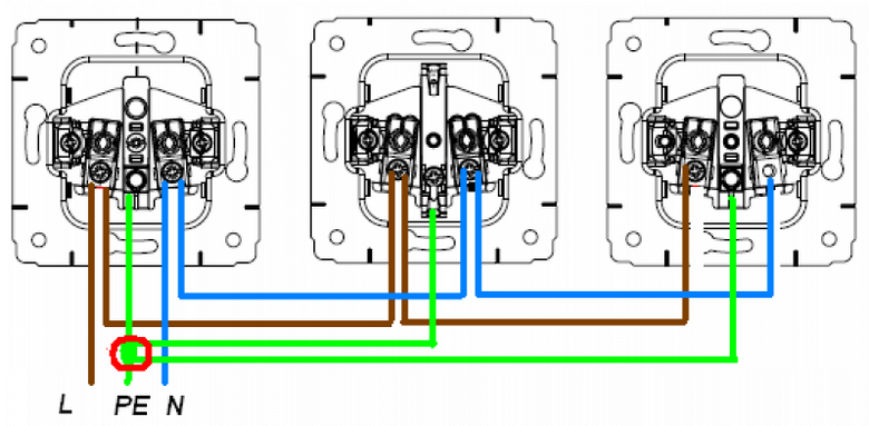
 In order to avoid problems, you must first correctly connect the wiring in the junction box. It should be remembered that the phase wire (usually this has brown, black or red insulation) must be connected to the twist of the phase wires. It is determined by the voltage indicator.Zero wire (blue, white) - with zero, "earth" (yellow, yellow-green) - with a grounded wire.
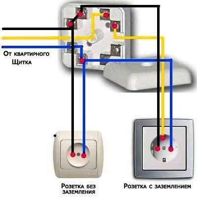
Now about how to connect an outlet with grounding. A mistake can be life-threatening: connecting the phase wire to the "ground" terminal will cause voltage to appear on the housing of the household appliance. To avoid this, you need to know the location of the socket terminals. "Earth" is connected to the central terminal. To the remaining two terminals - phase wire and zero (they can be interchanged).
Grounding is necessary for safety: it will prevent electric shock to a person when current leaks to the housing of household appliances. Therefore, the "earth" core of the cable connected to the outlet must be connected at the other end to the "earth" cores of the cables laid from the switchboard at the entrance.
How to connect a double socket
There are no special differences in the installation of such an outlet, since it will also have three terminals, like a single one. The only difference is the orientation of the body and the plug holes. Vertically installed may look different from those that are placed horizontally. The installation method does not affect anything and is selected based on personal wishes.
The socket is fixed in the socket, “frozen” with alabaster (it is applied with a spatula), and then its front panel is installed.
«>
not yet!
Mixed connection and grounding in series connection
If it is decided to use a series connection of sockets, it is possible to strengthen the overall design using a mixed method. The essence of the method is as follows:
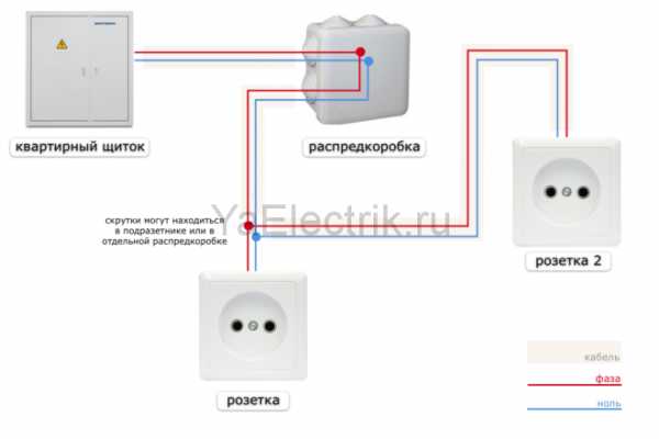
- A central cable is brought to the junction box from the common house panel.
- On the preliminary wiring plan, the most distant power access point is selected.
- The selected socket is connected from the switch box cable.
- From this device, the rest are powered.
This method increases the reliability of the network. If the socket fails, the rest continue to work. Shutting down the entire system is possible only in the event of a malfunction of the main cable, twisting in the junction box.
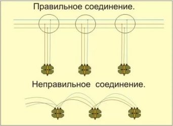
Grounding is a must. With a serial connection, if the wire burns out at one point, the rest are obtained without protection. The best way to connect sockets to each other for grounding is mixed. The main cable is fixed under the ceiling, then branches are made to each access point.
This technique has disadvantages - the large length of the wires used, the need to install several junction boxes (for each branch). To know for sure whether high-power devices can be connected to the network, it is necessary to calculate the voltage before the cabling stage. An accurate calculation will help you choose how to connect the sockets in the end - in series, in parallel or mixed.
Combined method
In some cases, it is necessary to simultaneously increase the capacity and voltage of the battery. For this, two combined connection methods are used:
- To begin with, several batteries are connected in series. In this way, the required operating voltage is achieved. At the second stage, several batteries are connected in parallel, obtained by connecting the batteries in series. Several serial circuits are being created to achieve the required capacity.
- The second method involves parallel switching batteries with the required capacity, after which they are connected in series to achieve the required current.
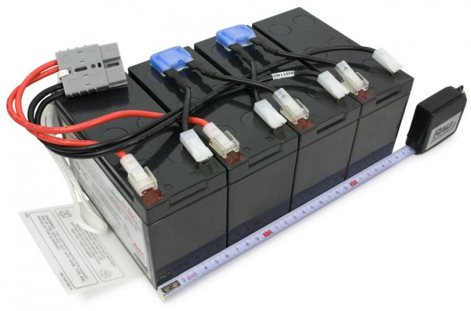
The combined method is used extremely rarely, as it involves the use of several power sources.
When choosing the most suitable batteries, attention is paid to their technical condition, capacity and voltage of the generated current.
Power connection procedure
To properly assemble the socket and connect, follow the instructions below:
- All work must begin with de-energizing the power line. To do this, turn off the machine in the switchboard to the desired line, if the installation is carried out on an existing wire.
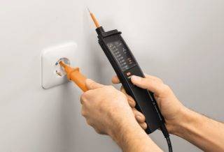
- Using a test lamp or a multimeter, we make sure that there is no voltage on the wire that will be connected.
- Wire stripping. The cable laid to connect the outlet, and which is already passed through the socket, must be prepared for connection. To do this, remove the wire insulation at a distance of 12-15 centimeters, trying not to damage the main insulation of the cores.
- To connect the outlet itself, we connect the bare strands of wires to the contacts. For a better contact, 4-6 millimeters of wire are twisted into a ring and put on the clamping screw of the terminal.
- Installing the socket in the mounting hole is done after connecting all the wires. Skews are not allowed. The wires must be carefully laid deep into the socket and fixed with presser feet.
- Installing the overlay.


How to connect the socket correctly
Not every home master, even with some experience in repair work, knows how to connect the outlet correctly in order to avoid problems such as a short circuit or overloading the mains.
On the one hand, such work does not take much time and does not require a large amount of specialized knowledge, on the other hand, failure to comply with the basic rules and installation features can lead to a fire hazard situation. Moreover, in a modern apartment and a private house, quite powerful equipment (from an electric kettle to an electric boiler) can be installed.
The increase in loads leads to the need to choose the right outlet and determine the scheme of its connection (if necessary, providing for grounding).
Compliance with safety regulations when installing sockets
Electrical work is classified as dangerous. Even a small voltage leads to burns, lesions and other unpleasant consequences. Compliance with safety precautions:
- de-energize the room in which the work is carried out;
- check the site before starting with a special device (you can turn on the device in the network);
- use rubber gloves, equipment with rubberized handles;
- when "building" the length, it is not enough to twist the wires, soldering is required;
- contact with connected bare cables is not allowed;
- the surplus should not “stick out” - shorten, lay in the wall;
- check whether the devices are suitable for the current and voltage levels used.
Open and closed wiring
The difference between the methods and noticeable to the naked eye.Closed wiring is located inside the wall, for which grooves (strobes) are punched or cut in it, in which the connecting wire is hidden under a layer of putty. Open wiring is laid along the surface of the wall, on which it is held in special fasteners or laid in plastic guides - cable channels.
Accordingly, if you can see the wires that fit the outlet, then the wiring is open. Otherwise, closed wiring is used, for which walls were cut.
These two ways in which the outlet is connected can be combined with each other - if the old points are connected in a closed way, then nothing prevents connecting a new one in an open way. There is no choice in only one case - in wooden houses, the socket can be connected exclusively in an open way, as well as the rest of the wiring.
Open wiring - advantages and disadvantages
To understand what open wiring is good for, an analogy with the most common extension cord (surge protector), which is essentially an additional branch of the mains, but is connected not to a junction box, but to an outlet, will help.
Advantages:
- To install a new outlet, you do not have to cut the wall. This is especially true for those premises that have already been renovated.
- For installation, no tools such as a wall chaser or puncher are needed.
- In the event of a breakdown, you do not have to open the wall - all the wiring is in front of your eyes.
- Mounting speed. Even after all the work has been completed, adding another point to the existing wiring is a matter of a few minutes.
- If desired, you can quickly completely change the wiring - ideal for temporary connection schemes.
Flaws:
- High probability of external influence on the wiring - children, pets, you can just accidentally catch it. This disadvantage is leveled by laying wires in cable channels.
- Open wires spoil the entire interior of the room. True, it all depends on the design abilities of the owner of the room - cable channels will fit perfectly into modern design solutions, and if the room is made in retro style, then special wires and other accessories are produced for this.
- The need to purchase special fasteners, even if cable channels are not used - in wooden houses, open wiring should be laid at a distance of 0.5-1 cm from the wall surface. Often wires are laid inside iron pipes - all these requirements are aimed at increasing the safety of using open electrical wiring.
As a result, this connection method justifies itself if, for some reason, it makes no sense to lay the wires to the outlet inside the wall. In addition to the fact that the wiring will be visible, there will be no differences in the operation of the outlet.
Hidden wiring - pros and cons
Despite some significant drawbacks, it is used almost everywhere - the advantages of its use still outweigh.
Advantages:
- The wires to the outlet fit in the wall, so wallpaper is freely glued on the outside or other finishes are made.
- Complies with all fire safety requirements (in concrete buildings) - even if a short circuit occurs, you can not be afraid of a fire from the wires in the wall.
- Very low probability of damage to the wiring - it can only be damaged while drilling the walls.
Flaws:
- For installation, you need to cut the walls.
- Difficult to do repairs.
- If the walls are finished, then after laying an additional outlet, you will have to redo it.
The disadvantages are leveled by preliminary calculations - if you plan in advance where and which block of sockets should be installed, then problems usually do not arise in the future.
Pros and cons
The final version of the wiring diagram
To determine the optimal connection scheme for sockets and switches, it is necessary to prepare a wiring plan, calculate the number of devices and the possible maximum power. At the same time, in newly built buildings, it is necessary to plan for future opportunities without too much modesty: an additional TV, buying a separate freezer, and the like.
Based on the received data, the type of connection is selected. The advantages of the sequential method include:
- simple connection system and circuit assembly;
- the ability to adjust the voltage level, to do less;
- one fuse per circuit can be used.
Parallel connection specifics
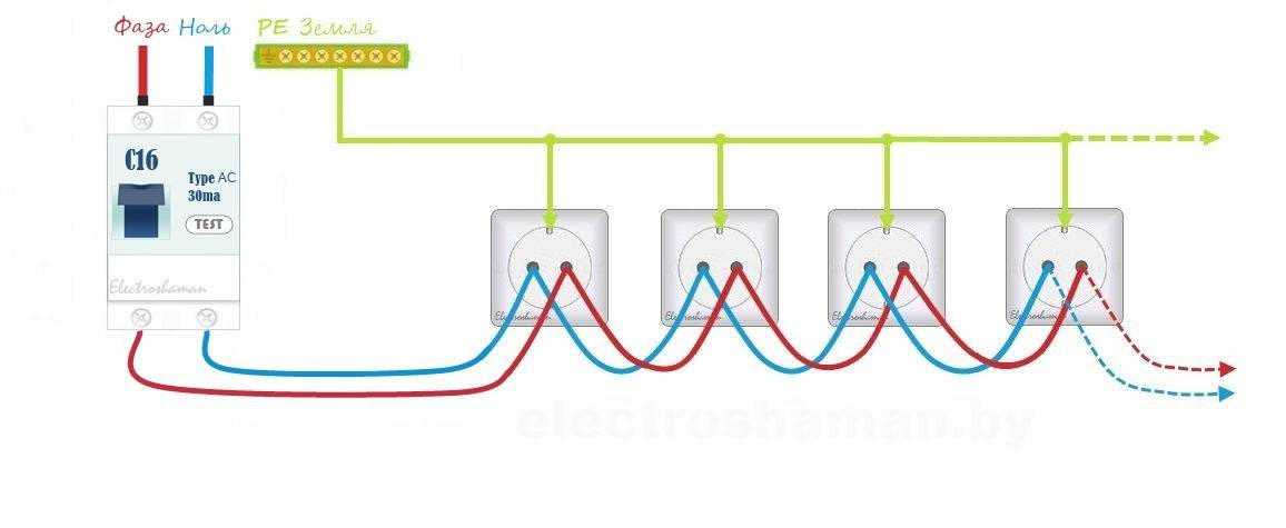
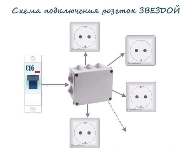
A feature of the parallel circuit for connecting sockets, otherwise called a "star", is a separate connection to the shield of each outlet. The third well-founded name is “boxless”, because. suggests the possibility of abandoning the junction box. The method is actively practiced in European countries, and in our country it is used to provide a separate line of powerful consumers, most often in combination with loop technology.
One of the options for a parallel circuit demonstrates a selection of photos:
Image gallery
Photo from
Step 1: Concealed parallel cabling
Step 2: Preparing the twin box for installation
Step 3: Fixing the socket boxes in the prepared wall
Step 4: Leveling the Wall Around the Installed Sockets
Step 5: Stripping the overall cable insulation
Step 6: Remove insulation from zero, phase and ground
Step 7: Parallel Installation of Outlets
Step 8: Installing and Fixing the Common Bezel
Plus "stars" in ensuring the maximum degree of security. A significant advantage lies in creating the ability to control large energy consumers separately, which is a priority for power distribution for Smart Homes, for example. The minus of the scheme lies in the impressive labor costs of the electrician and in the almost threefold increase in cable consumption.


A parallel circuit is also used to connect three-phase power outlets that will power powerful electrical appliances. In this case, the cross section of the conductors supplying such consumers should be at least 2.5 square meters. mm.
For greater reliability, they should have a small current margin. This will compensate for the actual deviation from the diameter specified by the manufacturer from their nominal value, which is often the “sin” of products presented on the modern market. In addition, such a solution will ensure the possibility of equipment operation in overload mode.
This method of installation is beneficial in that the performance of each individual point does not affect the functioning of the other participants in the chain. For household appliances, such a scheme is considered the most stable and safe.
The parallel method of connecting sockets ensures the independence of each power point: no matter how many sockets are present in the circuit, the voltage will remain uniform
The connection of a three-phase socket equipped with grounding is carried out using a separate four-wire wiring. The cable, which includes three phases, ground and zero, goes directly from the shield.
The purpose of the wire is easiest to determine by the color of the insulation:
- "phase" - wires with a white tint;
- "zero" - the insulation is colored blue;
- "grounding" - yellow-green braid.
Grounding is essentially a protective zero. In order for it to remain so, it is necessary to ensure its reliable and permanent connection throughout the entire line.
To connect the wires and connect to the outlet, first shorten their ends. The use of side cutters will allow you to do the job as accurately as possible. The end of each wire is stripped of 15-20 mm from external insulation with a sharp knife.
The wires are connected in the following sequence:
- Remove the plastic protective cover from the outlet.
- The clamping screws are unscrewed by 5-6 mm. The same manipulations are done with the screw and on the ground terminal.
- The stripped ends of the wires are alternately brought into the box, taking into account the position of the input terminals, and placed in the appropriate sockets.
- Sockets with laid wires are tightly tightened with screws.
- The socket with connected wires is inserted into the wall niche and fixed with side clips.
To obtain a more reliable assembly, some craftsmen roll the bare ends of the strands in the form of a loop or ring so that their diameter matches the size of the legs of the screws. After that, each screw is unscrewed in turn, its base is wrapped with a wire ring and tightly tightened.
The scheme is used not only for powering separately located sockets, but also for connecting blocks that include two or more points
When connecting socket blocks, all the advantages of the circuit are preserved. The only thing is that the connection process takes a little more time and effort.
Increased costs are not an argument for those for whom safety is a priority. If you look at the situation more globally, then sometimes it is better to immediately invest more money and effort by equipping an autonomous power line for the outlet. Then you don’t have to think every time about whether it is possible to use a point to connect one or another electrical appliance.
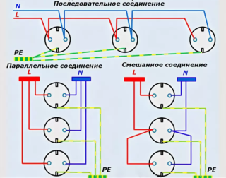
Connection methods
 Ways to connect sockets
Before connecting many power outlets in a row, it is important to understand the existing ways to connect them. Depending on the order of switching of individual conductors, the following options are distinguished:
- Parallel connection, in which the sockets must be connected with a "star".
- A serial connection, otherwise called a "loop".
- Combined inclusion using a loop and a "star".
- Ring connection.
Each of the listed methods is selected depending on the architecture of the room and considerations of savings on installation products. Parallel star connection is convenient when distributing the supply network from a single center (switchboard, for example).
The serial method (or loop) is used when a number of sockets installed one after the other are switched on on a given line. Individual contacts (phase and zero) are connected to each other in parallel, the serial method is called only because of the order in which the socket nodes are located.
With a combined inclusion in separate sections, the products are installed in a row, after which a “star” is arranged from one of them.
Conclusion
The choice of the method of connecting sockets is always determined by the power of the connected electrical equipment and the cost of installation work. The separate circuit ensures reliable and uninterrupted power supply to all devices. However, this method is the most expensive, as it requires more cable. But it is the star connection that guarantees the independent operation of all points.
It is also important to take into account that when connecting sockets in series, the total load should not exceed the maximum current of the socket. And it, in most cases, does not exceed 16A (3.5 kW)
Those. if you are going to install a block of 3 outlets and connect them in series, it is strictly forbidden to simultaneously turn on a load of more than 16A in each of these outlets (this situation is relevant in the kitchen). At the same time, if you decide to connect the sockets with a star, it will be possible to connect a load of up to 16A to each of them. The main thing is that the cable can withstand the machine that is installed on this outlet line.